2021 NISSAN ARMADA instrument panel
[x] Cancel search: instrument panelPage 132 of 603

2-40Instruments and controls
.Unlocking the door or opening the
liftgate without using the button on
the Intelligent Key, the door handle
request switch or the mechanical key.
(Even if the door is opened by releas-
ing the door inside lock knob, the
alarm will activate.)
. Opening the hood.
How to stop an activated alarm
The alarm will stop when a door is
unlocked by pushing the unlock button
on the Intelligent Key, the door handle
request switch or using the mechanical
key, or when the ignition switch is pushed
to the ACC or ON position.
If the system does not operate as
described above, it is recommended
you have it checked by a NISSAN dealer.
NISSAN VEHICLE IMMOBILIZER SYS-
TEM
The NISSAN Vehicle Immobilizer System
will not allow the engine to start without
the use of the registered Intelligent Key.
Never leave these keys in the vehicle.
FCC Notice:
For USA:
This device complies with Part 15 of the
FCC Rules. Operation is subject to the
following two conditions: (1) This device
may not cause harmful interference, and (2) this device must accept any
interference received, including inter-
ference that may cause undesired op-
eration.
NOTE:
Changes or modifications not expressly
approved by the party responsible for
compliance could void the user’s
authority to operate the equipment.
For Canada:
This device complies with Industry Ca-
nada licence-exempt RSS standard(s).
Operation is subject to the following
two conditions: (1) this device may not
cause interference, and (2) this device
must accept any interference, including
interference that may cause undesired
operation of the device.
SIC2045
Security indicator light
The security indicator light is located on
the meter panel. It indicates the status of
the NISSAN Vehicle Immobilizer System.
The light blinks after the ignition switch
was in the ACC, OFF and LOCK position.
This function indicates the security sys-
tems equipped on the vehicle are opera-
tional.
If the NISSAN Vehicle Immobilizer System
is malfunctioning, this light will remain on
while the ignition switch is in the ON
position.
If the light still remains on and/or the
engine will not start, seek service for
Page 139 of 603

SIC3784A
Be sure not to put anything on top of
the photo sensorlocated on the top
of the instrument panel. The photo
sensor controls the Intelligent Auto
Headlight system; if it is covered, the
photo sensor reacts as if it is dark and
the headlights will illuminate.
SIC3670
Headlight beam select
To select the low beam, put the lever in
the neutral position as shown.
To select the high beam, push the lever
forward while the switch is in the
position. Pull it back to select the low
beam.
Pulling the lever toward you will flash the
headlight high beam even when the
headlight switch is in the OFF position.
High beam assist
The high beam assist system will operate
when the vehicle is driven at approxi-
mately 25 MPH (40 km/h) and above.
If an oncoming vehicle or leading vehicle
appears in front of your vehicle when the
headlight high beam is on, the headlight
will be switched to the low beam auto-
matically.
Precautions on high beam assist:
WARNING
. The high beam assist system is a
convenience but it is not a sub-
stitute for safe driving operation.
The driver should remain alert at
all times, ensure safe driving
practices and switch the high
beam and low beam manually
when necessary.
. The high beam or low beam may
not switch automatically under
the following conditions. Switch
the high beam and low beam
manually.
— During bad weather (rain, fog,
snow, wind, etc.).
Instruments and controls2-47
Page 143 of 603

WAC0256X
When the instrument brightness control
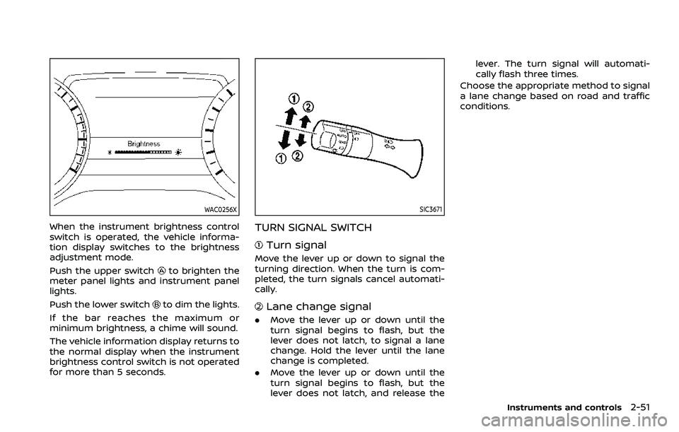
switch is operated, the vehicle informa-
tion display switches to the brightness
adjustment mode.
Push the upper switch
to brighten the
meter panel lights and instrument panel
lights.
Push the lower switch
to dim the lights.
If the bar reaches the maximum or
minimum brightness, a chime will sound.
The vehicle information display returns to
the normal display when the instrument
brightness control switch is not operated
for more than 5 seconds.
SIC3671
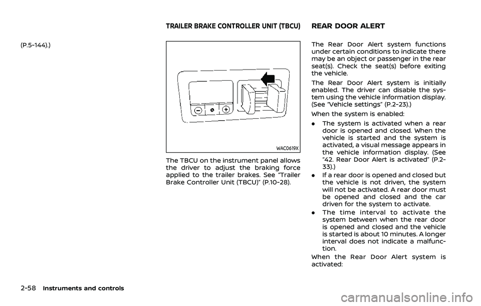
TURN SIGNAL SWITCH
Turn signal
Move the lever up or down to signal the
turning direction. When the turn is com-
pleted, the turn signals cancel automati-
cally.
Lane change signal
. Move the lever up or down until the
turn signal begins to flash, but the
lever does not latch, to signal a lane
change. Hold the lever until the lane
change is completed.
. Move the lever up or down until the
turn signal begins to flash, but the
lever does not latch, and release the lever. The turn signal will automati-
cally flash three times.
Choose the appropriate method to signal
a lane change based on road and traffic
conditions.
Instruments and controls2-51
Page 146 of 603

2-54Instruments and controls
WAC0524X
FRONT (if so equipped)
The front seats can be warmed by built-in
heaters. The switches located on the
instrument panel can be operated inde-
pendently of each other.
1. Start the engine.
2. Push the heated seat switch andselect the desired heat range.
.For high heat, push the switch once..For medium heat, push the switch
twice.
.For low heat, push the switch threetimes.
.The indicator lighton the switch
will illuminate depending on the
heat level when the heater is on. 3. To turn off the heater, push the
heated seat switch until the indicator
light turns off.
The heater is controlled by a control
module, automatically adjusting the
heat level to maintain comfort accord-
ing to the selected heat range.
The indicator light will remain on as
long as the switch is on.
When the vehicle’s interior is warmed,
or before you leave the vehicle, be
sure to turn off the seat heater.
SIC2770
REAR (if so equipped)
The 2nd row outboard seats are warmed
by built-in heaters. The switches located
on the back side of the center console
can be operated independently of each
other.
1. Start the engine.
2. Select heat range.
For high heat, push the HI (High)
side of the switch.
For low heat, push the LO (Low) side
of the switch.
The indicator light in the switch
will
illuminate when the heater is on.
Page 147 of 603

3. To turn off the heater, return theswitch to the level position. Make sure
the indicator light turns off.
The heater is controlled by a thermo-
stat, automatically turning the heater
on and off. The indicator light will
remain on as long as the switch is on.
When the vehicle’s interior is warmed,
or before you leave the vehicle, be
sure to turn off the switch.
WAC0640X
The climate controlled seat cools down
the front seats by blowing cool air from
the surface of the seat. The switches
located on the instrument panel can be
operated independently of each other.
1. Start the engine.
2. Push the climate controlled seatswitch to cool the seat. The indicator
light
on the corresponding switch
will illuminate depending on the cool
level.
3. Adjust the desired amount of air by pushing the switch again. The climate
controlled seat blower remains on low
speed for approximately 60 seconds
after pushing the switch on. 4. When the vehicle’s interior is warmed
or cooled, or before you leave the
vehicle, be sure to turn off the climate
controlled seats. To turn off the cli-
mate controlled seats, push the
switch until the indicator light turns
off.
To check the air filters for the climate
controlled seat, it is recommended
you visit a NISSAN dealer.
WARNING
Do not use or allow occupants to use
the climate controlled seats if you or
the occupants cannot monitor seat
temperatures or have an inability to
feel pain in those body parts in
contact with the seat. Use of the
climate controlled seats by such
people could result in serious injury.
CAUTION
.The battery could run down if the
climate controlled seat is oper-
ated while the engine is not run-
ning.
Instruments and controls2-55
CLIMATE CONTROLLED SEATS (if
so equipped)
Page 150 of 603

2-58Instruments and controls
(P.5-144).)
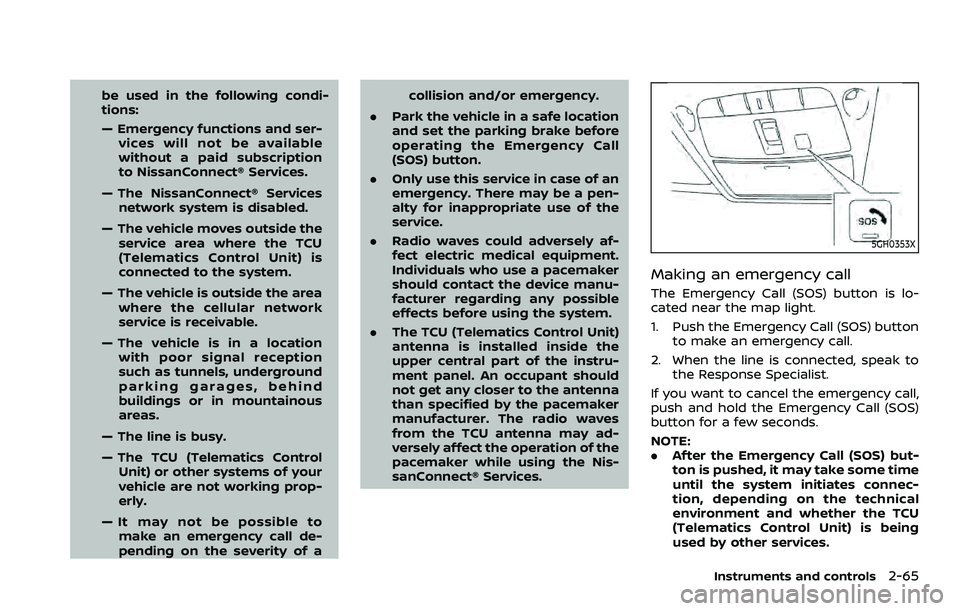
WAC0619X
The TBCU on the instrument panel allows
the driver to adjust the braking force
applied to the trailer brakes. See “Trailer
Brake Controller Unit (TBCU)” (P.10-28).
The Rear Door Alert system functions
under certain conditions to indicate there
may be an object or passenger in the rear
seat(s). Check the seat(s) before exiting
the vehicle.
The Rear Door Alert system is initially
enabled. The driver can disable the sys-
tem using the vehicle information display.
(See “Vehicle settings” (P.2-23).)
When the system is enabled:
.The system is activated when a rear
door is opened and closed. When the
vehicle is started and the system is
activated, a visual message appears in
the vehicle information display. (See
“42. Rear Door Alert is activated” (P.2-
33).)
. If a rear door is opened and closed but
the vehicle is not driven, the system
will not be activated. A rear door must
be opened and closed and the car
driven for the system to activate.
. The time interval to activate the
system between when the rear door
is opened and closed and the vehicle
is started is about 10 minutes. A longer
interval does not indicate a malfunc-
tion.
When the Rear Door Alert system is
activated:
TRAILER BRAKE CONTROLLER UNIT (TBCU)REAR DOOR ALERT
Page 152 of 603

2-60Instruments and controls
WAC0620XInstrument panel
The power outlet is located inside the lid.
Push the lid release button
up to open
the lid.
SIC4456
Back side of front console
SIC4391Luggage room
Type A (if so equipped)
The power outlet is used for powering
electrical accessories such as cellular
telephones.
CAUTION
. The outlet and plug may be hot
during or immediately after use.
. Do not use with accessories that
exceed a combined power draw
of 12 volts, 120W (10A) for all the
power outlets. Do not use double
adapters or more than one elec-
trical accessory.
. This power outlet is not designed
for use with a cigarette lighter
unit.
. Push the plug in as far as it will
go. If good contact is not made,
the plug may overheat or the
internal temperature fuse may
blow.
Page 157 of 603

be used in the following condi-
tions:
— Emergency functions and ser-vices will not be available
without a paid subscription
to NissanConnect® Services.
— The NissanConnect® Services network system is disabled.
— The vehicle moves outside the service area where the TCU
(Telematics Control Unit) is
connected to the system.
— The vehicle is outside the area where the cellular network
service is receivable.
— The vehicle is in a location with poor signal reception
such as tunnels, underground
parking garages, behind
buildings or in mountainous
areas.
— The line is busy.
— The TCU (Telematics Control Unit) or other systems of your
vehicle are not working prop-
erly.
— It may not be possible to make an emergency call de-
pending on the severity of a collision and/or emergency.
. Park the vehicle in a safe location
and set the parking brake before
operating the Emergency Call
(SOS) button.
. Only use this service in case of an
emergency. There may be a pen-
alty for inappropriate use of the
service.
. Radio waves could adversely af-
fect electric medical equipment.
Individuals who use a pacemaker
should contact the device manu-
facturer regarding any possible
effects before using the system.
. The TCU (Telematics Control Unit)
antenna is installed inside the
upper central part of the instru-
ment panel. An occupant should
not get any closer to the antenna
than specified by the pacemaker
manufacturer. The radio waves
from the TCU antenna may ad-
versely affect the operation of the
pacemaker while using the Nis-
sanConnect® Services.
5GH0353X
Making an emergency call
The Emergency Call (SOS) button is lo-
cated near the map light.
1. Push the Emergency Call (SOS) button
to make an emergency call.
2. When the line is connected, speak to the Response Specialist.
If you want to cancel the emergency call,
push and hold the Emergency Call (SOS)
button for a few seconds.
NOTE:
. After the Emergency Call (SOS) but-
ton is pushed, it may take some time
until the system initiates connec-
tion, depending on the technical
environment and whether the TCU
(Telematics Control Unit) is being
used by other services.
Instruments and controls2-65