2021 NISSAN ARMADA charging
[x] Cancel search: chargingPage 265 of 603

OPERATING TIPS
When the engine coolant temperature
and outside air temperature are low, the
air flow from the foot outlets may not
operate. However, this is not a malfunc-
tion. After the coolant temperature
warms up, the air flow from the foot
outlets will operate normally.
The sensors
andlocated on the
instrument panel help maintain a con-
stant temperature. Do not put anything
on or around the sensors.
LINKING INTELLIGENT KEY (if so
equipped)
The air conditioner system settings can
be memorized for each Intelligent Key.
For more details, see “Setting memory
function” (P.3-42).
IN-CABIN MICROFILTER
The air conditioner system is equipped
with an in-cabin microfilter which collects
dirt, pollen, dust, etc.
To make sure the air conditioner heats,
defogs, and ventilates efficiently, replace
the filter in accordance with the specified
maintenance intervals listed in the “9.
Maintenance and schedules” section. It is
recommended to see a NISSAN dealer to
replace the filter.
The filter should be replaced if the air flow decreases significantly or if win-
dows fog up easily when operating the
heater or air conditioner.
SERVICING AIR CONDITIONER
The air conditioner system in your NISSAN
is charged with a refrigerant designed
with the environment in mind.
This re-
frigerant will not harm the earth’s
ozone layer. However, special charging
equipment and lubricant are required
when servicing your NISSAN air condi-
tioner. Using improper refrigerants or
lubricants will cause severe damage to
your air conditioner system. (See “Capa-
cities and recommended fluids/lubri-
cants” (P.10-2) for air conditioner system
refrigerant and lubricant recommenda-
tions.)
Your NISSAN dealer will be able to service
your environmentally friendly air condi-
tioner system.
WARNING
The system contains refrigerant un-
der high pressure. To avoid personal
injury, any air conditioner service
should be done only by an experi-
enced technician with the proper
equipment.
WINDOW ANTENNA
The antenna pattern is printed inside the
rear side glass.
CAUTION
. Do not place metalized film near
the 3rd row seat window or at-
tach any metal parts to it. This
may cause poor reception or
noise.
. When cleaning the inside of the
rear side window, be careful not
to scratch or damage the rear
side window antenna. Lightly
wipe along the antenna with a
dampened soft cloth.
Monitor, heater, air conditioner, audio, phone and voice recognition systems4-41
ANTENNA
Page 427 of 603

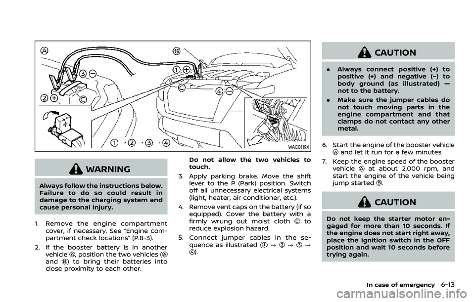
WAG0119X
WARNING
Always follow the instructions below.
Failure to do so could result in
damage to the charging system and
cause personal injury.
1. Remove the engine compartment cover, if necessary. See “Engine com-
partment check locations” (P.8-3).
2. If the booster battery is in another vehicle
, position the two vehicles (and) to bring their batteries into
close proximity to each other. Do not allow the two vehicles to
touch.
3. Apply parking brake. Move the shift lever to the P (Park) position. Switch
off all unnecessary electrical systems
(light, heater, air conditioner, etc.).
4. Remove vent caps on the battery (if so equipped). Cover the battery with a
firmly wrung out moist cloth
to
reduce explosion hazard.
5. Connect jumper cables in the se- quence as illustrated (
???).
CAUTION
.Always connect positive (+) to
positive (+) and negative (−) to
body ground (as illustrated) —
not to the battery.
. Make sure the jumper cables do
not touch moving parts in the
engine compartment and that
clamps do not contact any other
metal.
6. Start the engine of the booster vehicle
and let it run for a few minutes.
7. Keep the engine speed of the booster vehicle
at about 2,000 rpm, and
start the engine of the vehicle being
jump started
.
CAUTION
Do not keep the starter motor en-
gaged for more than 10 seconds. If
the engine does not start right away,
place the ignition switch in the OFF
position and wait 10 seconds before
trying again.
In case of emergency6-13
Page 457 of 603

Add a washer solvent to the washer for
better cleaning. In the winter season, add
a windshield washer antifreeze. Follow
the manufacturer’s instructions for the
mixture ratio.
Refill the reservoir more frequently when
driving conditions require an increased
amount of window washer fluid.
Recommended fluid is Genuine NISSAN
Windshield Washer Concentrate Cleaner
& Antifreeze or equivalent.
CAUTION
.Do not substitute engine anti-
freeze coolant for window
washer solution. This may result
in damage to the paint.
. Do not fill the window washer
reservoir tank with washer fluid
concentrates at full strength.
Some methyl alcohol based
washer fluid concentrates may
permanently stain the grille if
spilled while filling the window
washer reservoir tank.
. Pre-mix washer fluid concen-
trates with water to the manu-
facturer’s recommended levels
before pouring the fluid into the
window washer reservoir tank. Do not use the window washer re-
servoir tank to mix the washer
fluid concentrate and water.
.
Keep the battery surface clean and
dry. Clean the battery with a solution
of baking soda and water.
. Make certain the terminal connec-
tions are clean and securely tightened.
. If the vehicle is not to be used for 30
days or longer, disconnect the nega-
tive (−) battery terminal cable to pre-
vent discharging it.
NOTE:
Care should be taken to avoid situations
that can lead to potential battery dis-
charge and potential no-start condi-
tions such as:
1. Installation or extended use of elec-
tronic accessories that consume
battery power when the engine is
not running (Phone chargers, GPS,
DVD players, etc.)
2. Vehicle is not driven regularly and/
or only driven short distances.
In these cases, the battery may need to
be charged to maintain battery health.
WARNING
. Do not expose the battery to
flames or electrical sparks. Hy-
drogen gas generated by the
battery is explosive. Do not allow
battery fluid to contact your skin,
Do-it-yourself8-11
BATTERY
Page 459 of 603

JUMP STARTING
If jump starting is necessary, see “Jump
starting” (P.6-12). If the engine does not
start by jump starting, the battery may
have to be replaced. It is recommended
you visit a NISSAN dealer for this service.CAUTION
.Do not ground accessories di-
rectly to the battery terminal.
Doing so will bypass the variable
voltage control system and the
vehicle battery may not charge
completely.
. Use electrical accessories with
the engine running to avoid dis-
charging the vehicle battery.
The variable voltage control system mea-
sures the amount of electrical discharge
from the battery and controls voltage
generated by the generator.
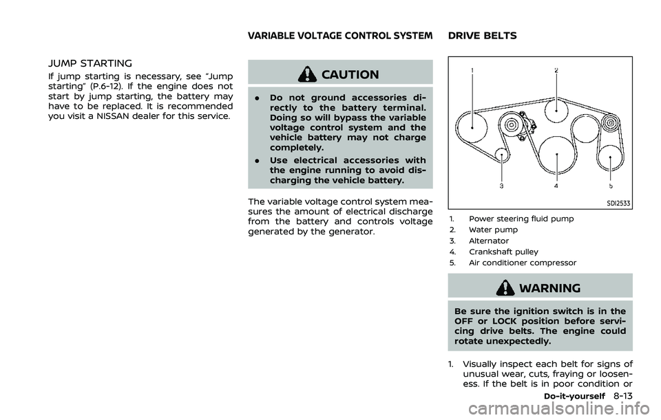
SDI2533
1. Power steering fluid pump
2. Water pump
3. Alternator
4. Crankshaft pulley
5. Air conditioner compressor
WARNING
Be sure the ignition switch is in the
OFF or LOCK position before servi-
cing drive belts. The engine could
rotate unexpectedly.
1. Visually inspect each belt for signs of unusual wear, cuts, fraying or loosen-
ess. If the belt is in poor condition or
Do-it-yourself8-13
VARIABLE VOLTAGE CONTROL SYSTEMDRIVE BELTS
Page 556 of 603

11-6
Push starting............................................................ 6-14
Starting the engine............................................. 5-16
Status light, Front passenger air bag ......... 1-62
Steering Heated steering wheel ..................................... 2-52
Power steering ................................................... 5-141
Power steering fluid .............................................. 8-8
Tilt/telescopic steering .................................... 3-29
Storage ........................................................................\
........ 2-66
Sun visors ........................................................................\
.. 3-29
Sunglasses holder....................................................... 2-68
Supplemental air bag warning labels ......... 1-72
Supplemental air bag
warning light .................................................... 1-73, 2-13
Supplemental restraint system........................ 1-54 Precautions on supplemental
restraint system .................................................... 1-54
Switch Emergency Call (SOS) button ..................... 2-64
Fog light switch ..................................................... 2-52
Hazard warning flasher switch .................... 6-2
Headlight switch ................................................... 2-46
Ignition switch ........................................................ 5-18
Intelligent Auto Headlight switch ............ 2-46
Power door lock switch ..................................... 3-5
SNOW mode switch ............................................ 2-57
Turn signal switch ............................................... 2-51
Vehicle Dynamic Control (VDC)
OFF switch ................................................................. 2-57
T
Tachometer........................................................................\
.. 2-7
Temperature gauge, Engine coolant
temperature gauge ....................................................... 2-7
Theft (NISSAN Vehicle Immobilizer System),
Engine start...................................................................\
... 2-40 Three-way catalyst......................................................... 5-4
Tilt/telescopic steering ........................................... 3-29
Tire
Pressure, Low tire pressure
warning light ............................................................ 2-15
Tires Flat tire........................................................................\
..... 6-3
Tire and Loading
information label................................ 8-30, 10-13
Tire chains.................................................................. 8-35
Tire dressing................................................................ 7-4
Tire pressure ............................................................ 8-28
Tire Pressure Monitoring
System (TPMS) ................................................ 5-5, 6-3
Tire rotation.............................................................. 8-36
Types of tires ........................................................... 8-34
Uniform tire quality grading .................... 10-36
Wheel/tire size ........................................................ 10-9
Wheels and tires .................................................... 8-28
Top Tether strap child restraints........................ 1-37
TOW mode ..................................................................... 5-134
TOW mode switch....................................................... 2-57
Towing Flat towing............................................................. 10-35
Tow truck towing................................................. 6-16
Towing a trailer.................................................. 10-19
Towing safety...................................................... 10-24
TPMS, Tire Pressure
Monitoring System ............................................. 5-5, 6-3 TPMS with Easy Fill Tire Alert......................... 5-8
Traffic Sign Recognition (TSR)........................... 5-23
Trailer Brake Controller Unit (TBCU) ............ 2-58
Trailer towing .............................................................. 10-19
Transceiver HomeLink®
Universal Transceiver ......................... 2-81, 2-85 Transmission
Automatic Transmission Fluid (ATF) ........ 8-8
Driving with
automatic transmission .................................. 5-18
Transmission shift lever lock release ..... 5-22
Transmitter (See remote keyless
entry system) .................................................................. 3-15
Traveling or registering your vehicle in
another country ........................................................ 10-11
Trip computer ................................................................ 2-36
Trip odometer ................................................................ 2-36
Turn signal switch ...................................................... 2-51
U
Underbody cleaning ...................................................... 7-3
Uniform tire quality grading ............................ 10-36
USB (Universal Serial Bus)
charging connector................................................... 2-61
V
Vanity mirror ................................................................... 3-40
Vanity mirror lights .................................................... 2-80
Variable voltage control system ..................... 8-13
Vehicle Dimensions ............................................................ 10-10
Identification number (VIN)....................... 10-11
Loading information ...................................... 10-15
Recovery (freeing a stuck vehicle) .......... 6-19
Security system...................................................... 2-38
Vehicle Dynamic Control (VDC)
OFF switch ................................................................. 2-57
Vehicle Dynamic Control
(VDC) system ........................................................ 5-144
Vehicle Dynamic Control (VDC)
warning light ............................................................ 2-18
Page 570 of 603

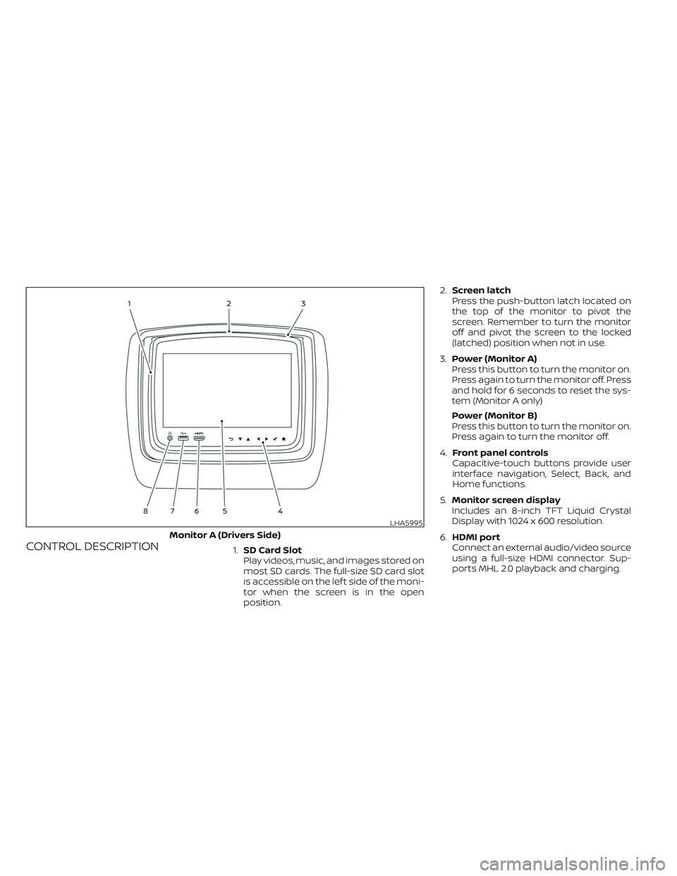
CONTROL DESCRIPTION1.SD Card Slot
Play videos, music, and images stored on
most SD cards. The full-size SD card slot
is accessible on the lef t side of the moni-
tor when the screen is in the open
position.2.Screen latch
Press the push-button latch located on
the top of the monitor to pivot the
screen. Remember to turn the monitor
off and pivot the screen to the locked
(latched) position when not in use.
3.Power (Monitor A)
Press this button to turn the monitor on.
Press again to turn the monitor off. Press
and hold for 6 seconds to reset the sys-
tem (Monitor A only)
Power (Monitor B)
Press this button to turn the monitor on.
Press again to turn the monitor off.
4.Front panel controls
Capacitive-touch buttons provide user
interface navigation, Select, Back, and
Home functions.
5.Monitor screen display
Includes an 8-inch TFT Liquid Crystal
Display with 1024 x 600 resolution.
6.HDMI port
Connect an external audio/video source
using a full-size HDMI connector. Sup-
ports MHL 2.0 playback and charging.
LHA5995
Monitor A (Drivers Side)
Page 599 of 603

SPECIFICATIONS
LCD Backlight TypeLED
Display Type 8.0 inch (Diagonal) a-Si TFT Active Matrix, 1024x3(RGB) x 600 resolution
Frequency Response 3.5mm Audio Output: 200Hz ~ 16kHz +/- 6dB
HDMI Support Version 1.4b, HDCP 2.1 Compliant
MHL Support Version 2.0, 900mA Maximum Charging Output
Wireless Audio 2-Channel Stereo Headphone Operation, (Typical Infrared Reception/Range: 0.9m; 80°, 1.8m; 50°)
Wi-Fi Network802.11b/g/n, TX/RX Frequency: 2412 MHz - 2484 MHz, Antenna 1: 802.11b, 802.11g, 802.11n HT20, 802.11n HT40, MIMO Antenna 1+2:
802.11n HT20
Wi-Fi Modulation 802.11b: DSSS (DBPSK / DQPSK / CCK), 802.11g/n: OFDM (BPSK / QPSK / 16QAM / 64QAM)
Bluetooth® Support Version 4.1
Bluetooth® BR/EDRTX/RX Frequency: 2402 MHz - 2480 MHz, Channels: 79, Bluetooth BR (1Mbps): GFSK Modulation, Bluetooth EDR (2Mbps): π/4-DQPSK
Modulation, Bluetooth EDR (3Mbps): 8-DPSK Modulation
Bluetooth® LETX/RX Frequency: 2402 MHz - 2480 MHz, Channels: 40, Carrier Frequency of Each Channel:, (37 hopping+3Advertisingchannel),
Type of Modulation: Bluetooth LE: GFSK
USB Support Version 1.1, Version 2.0 High Speed, 10 watt (2 Amp) Maximum Charging Output
SD Card Support SD, SDHC, SDXC