Page 293 of 545

Tr
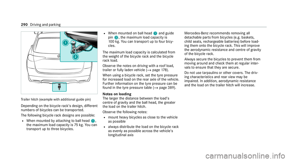
ailer hit ch(examp le with additional guide pin)
Depending on the bicycle rack 's design, dif fere nt
numbe rsof bicycles can be transpor ted.
The following bicycle rack designs are possible:
R When mounted byattaching toball head 1,
th e maximum load capacity is 75kg.Yo u can
transport up tothre e bicycles. R
When mounted on ball head 1and guide
pin 2, the maximum load capacity is
10 0kg .Yo u can transpo rtup tofour bicy‐
cles.
The maximum load capacity is calculated from
th ewe ight of the bicycle rack and the bicycle
ra ck load.
Obser vethe no tes on driving with a roof load,
trailer or fully laden vehicle (/ page178).
When using a bicycle rack , set the tyre pressure
fo r increased load on there ar axle of theve hicle.
Fu rther information on the tyre pressure can be
fo und in the tyre pressure table (/ page 389).
Note s on loading
The larger the dis tance between the load's
cent reof gr avity and the ball head, the greater
th e load on the trailer hitch.
Obser vethefo llowing no tes:
R mount heavy bicycles as close totheve hicle
as possible
R always distribute the load on the bicycle rack
as eve nly as possible across theve hicle's
longitudinal axis Mercedes-Benz
recommends removing all
de tach able parts from bicycles (e.g. bask ets,
ch ild seats, rech arge able bat teries) before load‐
ing them onto the bicycle rack . This will impr ove
th e aerodynamic resis tance and centre of gr avity
of the bicycle rack.
Alw ays secure the bicycles toprev ent them from
moving around and check them at regular inter‐
va ls to ensure that they are secure.
Do not use tarp aulins or other co vers. The driv‐
ing characteristics and rear view may be
impaired. In addition, aerodynamic resis tance
and the load on the trailer hitch will increase. 290
Driving and parking
Page 309 of 545

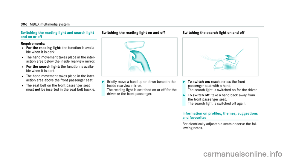
Switching
there ading light and sear chlight
and on or off Re
quirements:
R For the reading light: the function is availa‐
ble when it is dar k.
R The hand mo vement take s place in the inter‐
action area below the inside rearview mir ror.
R For the sear chlight: the function is availa‐
ble when it is dar k.
R The hand mo vement take s place in the inter‐
action area abo vethe front passenger seat.
R The seat belt on the front passenger seat
must notbe inser ted in the seat belt buckle. Switching
there ading light on and off #
Brief lymo vea hand up or down beneath the
inside rearview mir ror.
The reading light is swit ched on or off forthe
driver or the front passenger. Switching
the sear chlight on and off #
Toswitch on: reach across the front
passenger seat with a hand.
The sear chlight is switched on forth e driver. #
Toswitch off: take a hand back away from
th e front passenger seat.
The sear chlight is switched off again. Information on profiles,
themes, suggestions
and favo urites Fo
r electrical lyadjus table seats obser vethefo l‐
lowing no tes. 306
MBUX multimedia sy stem
Page 369 of 545
Wa
rning triangle Re
moving the warning triangle
Ve hicles with two rows of seats #
Remo ve wa rning triangle 1. Ve
hicles with threero ws of seats #
Remo ve wa rning triangle 1.
Setting up thewa rning triangle #
Fold side reflectors 1upwards toform a tri‐
angle and attach at theto p using upper
press-stud 2. #
Fold legs 3down and out tothe side. Fi
rs t-aid kit (soft-sided) overview 366
Breakdown assis tance
Page 372 of 545

Driving distance possible in eme
rgency
mode af ter the pressure loss warning: Load condition Driving distance pos‐
sible in emergency
mode
Pa rtially laden 80 km
Fu lly laden 30 kmThe driving dis
tance possible in emergency
mode may vary depending on the driving style.
Obser vethe maximum permissible speed of
80 km/h.
If a tyre has gone flat and cannot be replaced
with an MOEx tended tyre, you can use a stand‐
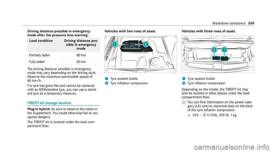
ard tyre as a temp orary measure. TIREFIT kit
storage location Plug-in
hybrid: be sure toobser vethe no tes in
th e Supplement. You could otherwise failto rec‐
ognise dangers.
The TIREFIT kit is loca ted under the load com‐
partment floor. Ve
hicles with two rows of seats 1
Tyre sealant bottle
2 Tyre inflation compressor Ve
hicles with threero ws of seats 1
Tyre sealant bottle
2 Tyre inflation compressor
Depending on the model, the TIREFIT kit may
also be located in other places under the load
compartment floor.
% You can find information on the po wer cate‐
gory (LK) and/or electrical data on the back
of the tyre inflation compressor:
R LK3 – 12V/20A, 240W, 1kg Breakdown assis
tance 369
Page 386 of 545
#
Make sure that the front and rear axles come
to rest on the same transpor tation vehicle.
* NO
TEDama getothe driv etra in due to
incor rect positioning #
Do not position theve hicle abo vethe
connection point of the transport vehi‐
cle. To
wing eyesto rage location Ve
hicles with two rows of seats To
wing eye1 is located under the load com‐
partment floor bythe tyre-change tool kit. Ve
hicles with threero ws of seats To
wing eye1 is located under the load com‐
partment floor. Installing
theto wing eye #
Press the mark on co ver1 inwa rds and
re mo ve. #
Screw intheto wing eyeclockwise as far as it
will go and tighten.
Ve hicles with a trailer hitch: vehicles with a
trailer hitch do not ha veare ar brac ketfo rthe Breakdown assis
tance 383
Page 393 of 545

If
th e preceding tyre sizes are complemented by
th e0091 symbol, the tyre pressure information
fo llowing sho wsalternative tyre pressures. Fuel
consum ption may then increase slightl y.
The load conditions "partially laden" and "fully
laden" are defined in theta ble for dif fere nt num‐
be rs of passengers and amounts of luggage. The
actual number of seats may dif fer from this. Ty
re pressure moni toring sy stem Fu
nction of the ty repressure moni toring sys‐
tem
The sy stem checks the tyre pressure and the
tyre temp erature of the tyres fitted totheve hicle
by means of a tyre pressu resensor.
The tyre pressure and the tyre temp erature
appear in the on-board computer (/ page 390).
If th ere is a subs tantial pressure loss or if the
tyre temp erature is excessive, you will be
wa rned with display messages (/ page478) or
th e0077 warning lamp in the instrument clus ter
( / page 500). The tyre pressure monitoring sy
stem is only an
aid. It is the driver's responsibility toset the tyre
pressure tothere commended cold tyre pressure
suitable forth e operating situation.
In most cases, the tyre pressure monitoring sys‐
te m will auto matically update the new refere nce
va lues af teryo u ha vechanged the tyre pressure.
Yo u can, ho wever,also update there fere nce val‐
ues byrestarting the tyre pressure monitoring
sy stem manually (/ page 391).
Sy stem limits
The sy stem may be impaired or may not function
particularly in thefo llowing situations:
R incor rect refere nce values weretaught in
R sudden pressure loss caused byafo re ign
object penetrating the tyre, forex ample
R there is a malfunction caused byano ther
ra dio signal source
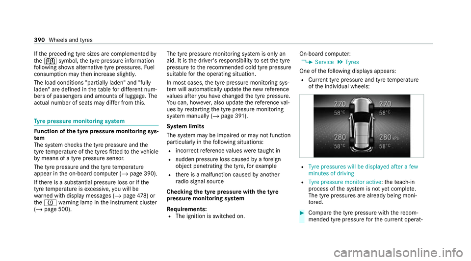
Checking the ty repressure with the tyre
pressure moni toring sy stem
Requ irements:
R The ignition is switched on. On-board computer:
4 Service 5
Tyres
One of thefo llowing displa ysappears:
R Cur rent tyre pressure and tyre temp erature
of the individual wheels: R
Tyre pressures will be displayed after a few
minutes of driving
R Tyre pressure monitor active: thete ach-in
process of the sy stem is not yet compl ete.
The tyre pressures are already being moni‐
to re d. #
Compare the tyre pressure with there com‐
mended tyre pressure forth e cur rent operat‐ 390
Wheels and tyres
Page 445 of 545
Display messages
Possible causes/consequences and 0050 0050Solutions #
Drive more slowl y. #
Repeat thege ar change.
LOW RANGE Max. speed
40 km/h *T
he maximum speed of 40 km/h forth ege ar change has been exceeded. #
Drive more slowl y. #
Todeactivate thege ar change, press theLOW RANGE button again. #
Repeat thege ar change.
Gearbox protection Limit
30 km/h Switch off LOW
RANGE *T
he oil temp erature in the transfer case is too high. #
Inthe on-ro ad position, shift toHIGH RANGE.
Anti-theft alarm system
Malfunction *T
he anti-theft alarm sy stem is malfunctioning. #
Consult a qualified specialist workshop.
006F Cannot fold 2nd seat row
forwards See Owner's Man-
ual *T
he seat backrests on the second rowof seats cannot befolded forw ard. #
Check therequ irements forfo lding forw ard the seat backrests on the second row of seats (/ page106). 442
Displaymessa ges and warning/indicator lamps
Page 446 of 545
Display messages
Possible causes/consequences and 0050 0050Solutions
006F 2nd seat row, left Not
locked *T
he left-hand seat or the seat backrest in the second rowof seats is not engaged. #
Foldthe cor responding seat backrest back until it engages and push thero w of seats back (/ page106). #
Makesure that the seat is engaged (/ page106).
006F
2nd seat row, righ t Not
locked *T
heright-hand seat or the seat backrest in the second rowof seats is not engaged. #
Foldthe cor responding seat backrest back until it engages and push thero w of seats back (/ page106). #
Makesure that the seat is engaged (/ page106).
00B2
Top up washer fluid *T
hewasher fluid le vel in thewa sher fluid reser voir has dropped below the minimum. #
Top up thewa sher fluid (/ page 355).
Wiper malfunctioning *T
he windscreen wiper is malfunctioning. #
Restart the engine.
If th e display message still appears: #
Consult a qualified specialist workshop. Display messages and
warning/indicator lamps 443