2021 MERCEDES-BENZ GLE COUPE overheating
[x] Cancel search: overheatingPage 111 of 525
Switching
the seat heating on/off &
WARNING Risk of burn s duetorepeat‐
edly switching on the seat heating
Re peatedly switching on the seat heating can
cause the seat cushion and seat backrest
padding tobecome very hot.
In particular, the health of persons with limi‐
te dte mp erature sensitivity or a limited ability
to react tohigh temp eratures may be af fec‐
te d or they may even suf fer burn-like injuries. #
Do not repeatedly switch on the seat
heating. To
protect against overheating, the seat heating
may be temp orarily deactivated af ter it is
switched on repeatedly.
* NO
TEDama getothe seats caused by
objects or documents when the seat
heater is switched on When
the seat heater is switched on, over‐
heating may occur due toobjects or docu‐ ments placed on
the seats e.g. seat cushions
or child seats. This could cause damage to
th e seat sur face. #
Makesure that no objects or docu‐
ments are on the seats when the seat
heater is switched on. Re
quirements:
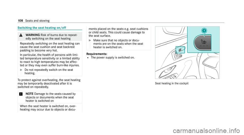
R The po wer supply is switched on. Seat heating in
the cockpit 108
Seats and stowing
Page 171 of 525
&
DANG ER Risk of death caused by
ex haust gases
Combustion engines emit poisonous exhaust
ga ses such as carbon monoxide. Inhaling
th ese exhaust gases is hazardous tohealth
and leads topoisoning. #
Never lea vethe engine or, if present,
th e auxiliary heating running in an
enclosed space wi thout suf ficient venti‐
lation. &
WARNING Risk of skidding and of an
accident due toshifting down on slippery
ro ad sur faces
If yo u shift down on slippery road sur faces to
inc rease the engine braking ef fect, the drive
wheels may lose traction. #
Do not shift down on slippery road sur‐
fa ces toinc rease the engine braking
ef fect. &
DANG ER Risk of fata l injury due topoi‐
sonous exhaust gases
If th eta ilpipe is bloc ked or suf ficient ventila‐
tion is not possible, poisonous exhaust gases
such as carbon monoxide may enter theve hi‐
cle. This is the case when theve hicle
becomes stuck in sn ow,fo rex ample. #
Keep theta ilpipe and the area around
th eve hicle free from snow when the
engine or thest ationary heater are run‐
ning. #
Open a window on the side of theve hi‐
cle facing away from the wind toensure
an adequate supply of fresh air. &
WARNING Risk of accident due tothe
brake sy stem overheating
If yo u lea veyour foot on the brake pedal
when driving, the brake sy stem may over‐
heat.
This increases the braking dis tance and the
brake sy stem may even cause the brake sys‐
te m failure. #
Never use the brake pedal as a foot re st. #
Do not depress the brake pedal and the
accelerator pedal at the same time
while driving. *
NO
TEEngine damage duetoexcessively
high engine speeds The engine will be damaged if
you drive with
th e engine in theov errevving range. #
Do not drive wi th the engine in theove r‐
re vving range. *
NO
TECausing wearto the brake linings
by permanently depressing the brake
pedal #
Do not permanently depress the brake
pedal while driving. #
Touse braking ef fect of the engine,
shift toa lo werge ar in good time. 16 8
Driving and pa rking
Page 241 of 525
R
When driving at speeds abo veappr oximately
14 0 km/h, theve hicle is lo wered.
R When driving at speeds below appr oximately
40 km/h, theve hicle is raised again.
Drive program C:
R The suspension setting is firm er.
R The vehicle is lo weredto sport le vel.
Drive prog ram B:
R The suspension setting is evenfirm er.
R The vehicle is lo weredto Sport + le vel.
Drive program F:
R The suspension setting is suitable for easily
negotiable off-road terrain.
R The vehicle is set tooff-road le vel +1 (raised
le ve l).
R When driving at speeds abo veappr oximately
80 km/h, theve hicle is lo wered.
R When driving at speeds below appr oximately
45 km/h, theve hicle is raised.
Individual suspension settings can be called up
in drive progra m= (/page 179). If
th e entry /exit le vel function is activated, the
ve hicle is lo weredto the Sport + le velto facili‐
ta te entering/exiting theve hicle. When driving
at speeds of appr oximately 30 km/h or abo ve,
th e entry /exit le vel is deactivated and theve hi‐
cle is raised (/ page240).
Dif fere nces between diff erentvehicle le vels
compared tothe normal le vel:
R Car wash: appr ox. +90 mm(/ page 342)
R Raised le vel:appr ox. +50 mm
R Spo rt:appr ox. -15 mm
R Spo rt+: appr ox. -25 mm
% Car wash le vel is 40 mm abo vethe maxi‐
mum vehicle height (raised le vel). Driving
into underground car par ksat car wash le vel
ri sks damaging theve hicle. Operation with a trailer or bicycle
rack
If transport equipment, forex ample a trailer or
bicycle rack , is attached tothe trailer hitch and
th e electrical connection has been cor rectly
es tablished:
R In drive program F,theve hicle adopts
th e normal le velst arting from a speed of
30 km/h.
R In all other drive programs, theve hicle
re mains at normal le vel ir respective of
speed.
Sy stem limits
AIRMATIC may not be available or ha veonly limi‐
te dav ailability in thefo llowing cases:
R The overheating pr otection has been activa‐
te d due tofrequent le velch anges within a
short time. The 00C4warning lamp appears
in the multifunction displa y.
Af terth e cooling phase, the sy stem is again
av ailable without restriction. 238
Driving and park ing
Page 357 of 525
Obser
vethefo llowing if you come into con‐
ta ct with th e tyre sealant: #
Rinse off the tyre sealant from your skin
using water immediatel y. #
If tyre sealant gets into your eyes, thor‐
oughly rinse them using clean water
immediatel y. #
If tyre sealant has been swallowe d,
th oroughly rinse out your mouth imme‐
diately and drink plenty of water.Do not
induce vomiting and seek medical
attention immediately. #
Change out of clo thing which has come
into con tact with tyre sealant immedi‐
ately. #
If an alle rgic reaction occurs, seek med‐
ical attention immediatel y.*
NO
TEOverheating due tothe tyre infla‐
tion compressor running too long #
Do not runth e tyre inflation compres‐
sor for longer than ten minu tes without
inter ruption. Comply with
the manufacturer's saf ety no tes on
th est icke r on the tyre inflation compressor.
Ha ve the tyre sealant bottle replaced in a quali‐
fi ed specialist workshop every five years. #
Do not remo veany fore ign objects which
ha ve entered the tyre. #
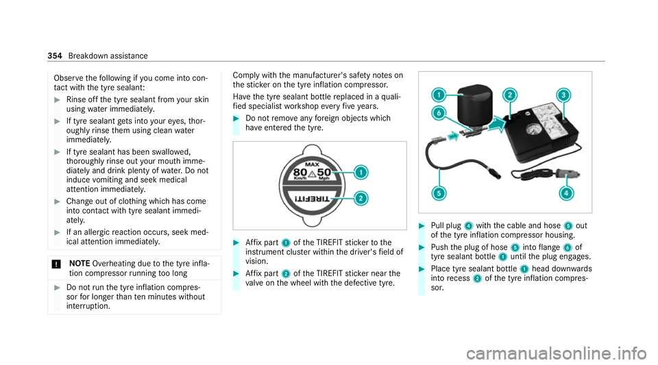
Affix pa rt1 ofthe TIREFIT sticke rto the
instrument clus ter within the driver's field of
vision. #
Affix pa rt2 ofthe TIREFIT sticke r near the
va lve on the wheel with the defective tyre. #
Pull plug 4with the cable and hose 5out
of the tyre inflation compressor housing. #
Push the plug of hose 5into flange 6of
tyre sealant bottle 1until the plug engages. #
Place tyre sealant bottle 1head down wards
into recess 2ofthe tyre inflation compres‐
sor. 354
Breakdown assis tance
Page 387 of 525
Emer
gency spare wheel Note
s onthe emer gency spare wheel &
WARNING Risk of accident caused by
incor rect wheel and tyre dimensions
The wheel or tyre size and the tyre type of
th e emer gency spa rewheel or spare wheel
and the wheel tobe replaced may dif fer. The
emer gency spa rewheel or spare wheel can
significantly impair driving characteristics of
th eve hicle.
To preve nt hazardous situations: #
Drive carefully. #
Neverfit more than one emer gency
spa rewheel or spare wheel that dif fers
in size. #
Only use an emer gency spa rewheel or
spare wheel brief ly.#
Do not deacti vate ESP ®
. #
Have the emer gency spa rewheel or
spare wheel of a dif fere nt size replaced
at the nearest qualified specialist work‐ shop. The new wheel must ha
vethe
cor rect dimensions. %
The emergency spa rewheel is fastened in
th e load compartment under the load com‐
partment floor.
% Not for Mercedes-Maybach vehicles.
Obser vethefo llowing no tes on fitting an emer‐
ge ncy spa rewheel:
R Check the tyre pressure of the emer gency
spa rewheel fitted. Co rrect the pressure as
necessar y.
R The maximum permissible speed with an
emer gency spa rewheel fitted is 80 km/h.
R Do not fit th e emer gency spa rewheel with
sn ow ch ains.
R Replace the emer gency spa rewheel af ter six
ye ars at the latest, rega rdless of wear.
% Ve
hicles with a tyre pressure monitoring
sy stem: if an emer gency spa rewheel is fit‐
te d, the tyre pressure monitoring sy stem
cann otfunction reliabl y.Fo r a few minutes
af te r an emer gency spa rewheel is fitted, the sy
stem may still display the tyre pressure of
th ere mo ved wheel. Only restart the sy stem
again when the emer gency spa rewheel has
been replaced with a new wheel.
Be sure toalso obse rveth efo llowing fur ther
re lated subjects:
R Notes on tyre pressure (/ page371)
R Tyre pressure table (/ page372)
R Notes on fitting tyres (/ page 374) Inflating
the emer gency spare wheel *
NO
TEOverheating due tothe tyre infla‐
tion compressor running too long #
Do not runth e tyre inflation compres‐
sor for longer than ten minu tes without
inter ruption. Re
quirements:
Comply with the manufacturer's saf ety no tes on
th est icke r of the emer gency spa rewheel and on
th e tyre inflation compressor. 384
Wheels and tyres
Page 390 of 525
#
Alw aysst ore the collapsible spare
wheel in the emer gency spa rewheel
bag and attach it tothe brac ket in the
load compartment. #
Alw ays ensure that the lashing stra ps
on the emer gency spa rewheel bag are
safely secured on there ar tie-down
ey es on the load compartment floor. Depending on
theve hicle's equipment, the col‐
lapsible spare wheel is located in an emer gency
spa rewheel bag on a brac ket in the load com‐
partment. The collapsible spare wheel in the
emer gency spa rewheel bag and the brac ket are
lashed wi thstra ps and secured using there ar
tie-down eyes on the load compartment floor. Re
moving the collapsible spare wheel Ve
hicles without a Burmes ter sound sy stem
The collapsible spare wheel is located under the
load compartment floor. #
Obser vethe information on mounting tyres
(/ page 374). #
Open theta ilgate. #
Open the load compartment floor. #
Remo vethe collapsible spare wheel.
Ve hicles with a Burmes ter sound sy stem
The collapsible spare wheel is secured in the col‐
lapsible spare wheel bag in the load compart‐
ment. #
Obser vethe information on mounting tyres
(/ page 374). #
Open the load compartment. #
Loosen the lashing stra ps. #
Unhook there taining spring hooks of the
lashing stra ps from the brac kets. #
Remo vethe collapsible spare wheel bag
to ge ther with the collapsible spare wheel. #
Open the collapsible spare wheel bag and
re mo vethe collapsible spare wheel. Inflating
the collapsible spa rewheel Re
quirements:
R Mount the collapsible spare wheel as descri‐
bed (/ page 382).
R Remo vethe tyre inflation compressor from
th estow agewell under the boot floor
(/ page 352).
* NO
TEDama getothe collapsible spare
wheel when lo wering theve hicle Lo
we ring theve hicle without pr eviously
inflating the collapsible spare wheel can
damage its rim. #
Inflate the collapsible spare wheel using
th e tyre inflation compressor before
lo we ring theve hicle. *
NO
TEOverheating due tothe tyre infla‐
tion compressor running too long #
Do not runth e tyre inflation compres‐
sor for longer than ten minu tes without
inter ruption. Wheels and tyres
387
Page 404 of 525
#
Have the brake fluid rene we d at the
specified inter vals. Ha
ve the brake fluid regularly replaced at a
qu alified specialist workshop.
Only use a brake fluid appr ovedby Mercedes-
Benz according toMB-F reigabe or MB-Appr oval
33 1.0. Coolant
Note
s on coolant
Obser vethe no tes on operating fluids
(/ page 393). &
WARNING Risk offire ‑ and inju ryfrom
antifreeze
If antifreeze comes into contact with hot
component parts in the engine compart‐
ment, it may ignite. #
Allow the engine tocool down before
yo uto p up the antif reeze. #
Make sure that no antifreeze spills out
next tothefiller opening. #
Thoroughly clean the antif reeze from
component parts before starting the
ve hicle. *
NO
TEDama gecaused byincor rect cool‐
ant #
Only use coolant that has been pre‐
mixed with therequ ired antifreeze pro‐
te ction.
Information on coolant is available at thefo l‐
lowing locations:
R inthe Mercedes-Benz Specification for
Operating Fluids 310.1
- at https://be vo.mercedes-benz.com
- inthe Mercedes-Benz BeVo app
R at a qualified specialist workshop *
NO
TEOverheating at high outside tem‐
peratures If an inapp
ropriate coolant is used, the
engine cooling sy stem is not suf ficiently pro‐ te
cted against overheating and cor rosion at
high outside temp eratures. #
Alw ays use coolant appr ovedby
Mercedes-Benz. #
Obser vethe instructions in the
Mercedes-Benz Specifications for Oper‐
ating Fluids 310.1. Ha
ve the coolant regularly replaced at a qualified
specialist workshop.
Proportion of antifreeze concentrate in the
engine cooling sy stem:
R a minimum of 50% (antifreeze pr otection
down toappr oximately -37°C)
R a maximum of 55% (antifreeze pr otection
down to-45°C) Note
s on windscreen washer fluid Obser
vethe no tes on operating fluids
(/ page 393). Te
ch nical da ta401
Page 432 of 525
Display messages
Possible causes/consequences and 0050 0050Solutions #
Consult a qualified specialist workshop.
Stop vehicle Leave engine
running Wait Transmission
cooling *T
he transmission is overheating. Pulling away may be temp orarily impaired or not possible. #
Stop theve hicle immediately in accordance with the traf fic conditions. Do not continue driving. #
Lea vethe engine running. #
Wait until the display message disappears before pulling away.
Auxiliary battery malfunc-
tion (whitedisplay mes‐
sage) *
Ve hicles with automatic transmission: The auxiliary batteryforth e transmission is no longer being charge d. #
Consult a qualified specialist workshop. #
Vehicles with automatic transmission: Untilthen, alw ays select park position 005Dmanually before you swit ch
off the engine. #
Before leaving theve hicle, apply the electric parking brake.
Auxiliary battery malfunc-
tion (red display message) *
Ve hicles with automatic transmission: The auxiliary batteryforth e transmission is no longer being charge d. #
Consult a qualified specialist workshop. #
Vehicles with automatic transmission: Untilthen, alw ays select park position 005Dmanually before you swit ch
off the engine. #
Before leaving theve hicle, apply the electric parking brake. Display messages and
warning/indicator lamps 429