2021 MERCEDES-BENZ GLC COUPE wheel
[x] Cancel search: wheelPage 228 of 481
The sy
stem evaluates images from thefo llowing
cameras:
R Reversing camera
R Front camera
R Two side cameras in the outside mir rors
% You can open the co ver of there ve rsing
camera manually (/ page 228).
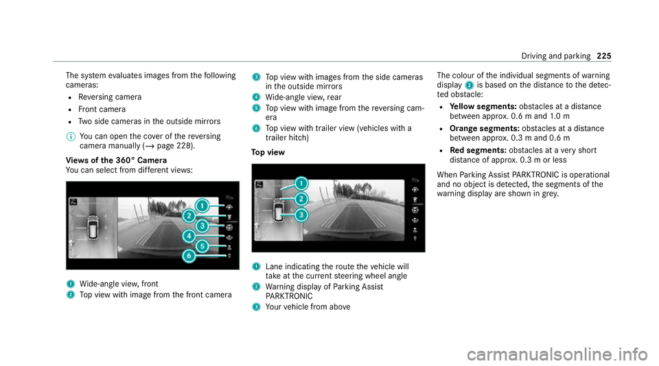
Vi ew s of the 360° Camera
Yo u can select from dif fere nt vie ws: 1
Wide-angle vie w,front
2 Top view with image from the front camera 3
Top view with images from the side cameras
in the outside mir rors
4 Wide-angle vie w,rear
5 Top view with image from there ve rsing cam‐
era
6 Top view with trailer view (vehicles with a
trailer hitch)
To p view 1
Lane indicating thero ute theve hicle will
ta ke atthe cur rent steering wheel angle
2 Warning display of Parking Assist
PA RKTRONIC
3 Your vehicle from abo ve The colour of
the individual segments of warning
display 2is based on the dis tance tothe de tec‐
te d obs tacle:
R Yellow segments: obstacles at a di stance
between appr ox. 0.6 m and 1.0 m
R Orange segments: obstacles at a di stance
between appr ox. 0.3 m and 0.6 m
R Red segments: obstacles at a very short
dis tance of appr ox. 0.3 m or less
When Parking Assist PARKTRONIC is operational
and no object is de tected, the segments of the
wa rning display are shown in gr ey. Driving and pa
rking 225
Page 229 of 481
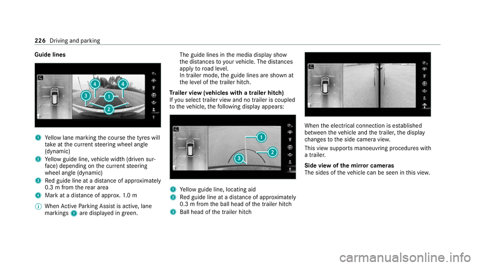
Guide lines
1
Yellow lane marking the course the tyres will
ta ke atthe cur rent steering wheel angle
(dynamic)
2 Yellow guide line, vehicle width (driven sur‐
fa ce) depending on the cur rent steering
wheel angle (dynamic)
3 Red guide line at a dis tance of appr oximately
0.3 m from there ar area
4 Mark at a distance of appr ox.1. 0 m
% When Active Parking Assist is active, lane
markings 1are displa yed in green. The guide lines in
the media display show
th e dis tances to yourvehicle. The dis tances
apply toroad le vel.
In trailer mode, the guide lines are shown at
th e le vel of the trailer hitch.
Tr ailer view (vehicles with a trailer hitch)
If yo u select trailer view and no trailer is coupled
to theve hicle, thefo llowing display appears: 1
Yellow guide line, locating aid
2 Red guide line at a dis tance of appr oximately
0.3 m from the ball head of the trailer hitch
3 Ball head of the trailer hitch When
the electrical connection is es tablished
between theve hicle and the trailer, the display
ch anges tothe side camera vie w.
This view supports manoeuvring procedures with
a trailer.
Side view of the mir ror cameras
The sides of theve hicle can be seen in this vie w. 226
Driving and parking
Page 230 of 481

1
Guide line of extern al vehicle dimensions
with outside mir rors folded out
2 Marker of the wheel conta ct points
Sy stem failure
If th e sy stem is not ready for operation, thefo l‐
lowing message appears in the media display: Sy
stem limits
The 360° Camera will not function or will only
partially function in thefo llowing situations:
R The doors are open.
R the outside mir rors are folded in.
R The tailgate is open.
R There is heavy rain, snow or fog.
R The light conditions are poor, e.g. at night.
R Cameras, or vehicle components in which
th e cameras are fitted, are dama ged, dirty or
co vered. Obser vethe information on vehicle
sensors and cameras (/ page184).
% Do not use the 360° Camera under such cir‐
cums tances. You could otherwise injure oth‐
ers or collide with objects when parking the
ve hicle.
Fo rte ch nical reasons, thest andard height of the
ve hicle may be altered if theve hicle is car rying a
heavy load and can result in inaccuracies in the
guide lines and in the display of thege nerated
ima ges. %
The contra stof the display may be impaired
by abrupt, direct sunlight or by other light
sources, e.g. when driving out of a garage . In
th is case, pay particular attention.
% Have the display repaired or replaced if, for
ex ample, pixel er rors considerably restrict its
use.
See the no tes on cleaning the 360° Camera
(/ page 309).
Calling up the view of the 360° Camera
using reve rsege ar
Re quirements:
R The Auto reversing camera function is activa‐
te d in the multimedia sy stem (/ page 228). #
Shift toreve rsege ar. #
Select the desired view in the multimedia
sy stem (/ page 224). #
If, af ter shifting toreve rsege ar, the image of
th ere ve rsing camera is not shown: switch off
th e ignition, press and hold thec button,
switch on the ignition and engage reve rse
ge ar again. Driving and parking
227
Page 238 of 481
%
The turn signal indicator is switched on auto‐
matically when the parking procedure
begins.
Yo u are responsible for selecting the turn signal
indicator in accordance with the traf fic condi‐
tions. If necessar y,select the turn signal indica‐
to r according ly. &
WARNING Risk of accident due tovehi‐
cle swinging out while parking or pulling
out of a parking space
While parking or exiting a parking space, the
ve hicle swings out and can drive onto areas
of the oncoming lane.
This could cause youto collide wi thobjects
or other road users. #
Pay attention toobjects and other road
users. #
Where necessar y,stop theve hicle or
cancel the parking procedure with
Ac tive Parking Assist. #
If,forex ample, thePlease engage reverse
gear message appears in the media display: select
the cor responding transmission posi‐
tion.
The vehicle drives into the selected parking
space.
% During the parking procedure with Active
Pa rking Assist, the lane markings are dis‐
pla yed in green in the camera image.
On completion of the parking procedure, the
Ø Parking Assist finished, take control of
vehicle display message appears. Further
manoeuvring may still be necessar y. #
After completion of the parking procedure,
safeguard theve hicle against rolling away.
When requ ired bylegal requirements or local
conditions: turn the wheels towa rdsth eke rb.
% You can stop theve hicle and change the
transmission position du ring the parking pro‐
cedure. The sy stem then calculates a new
ve hicle path. If no new vehicle path is availa‐
ble, the sy stem can change the transmission
position again or cancel the parking proce‐
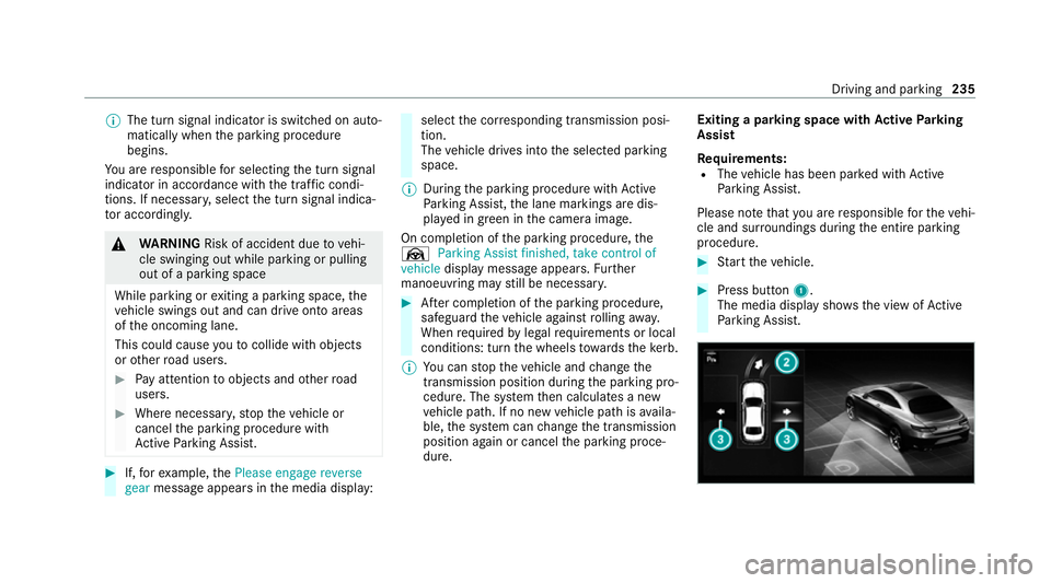
dure. Exiting a parking space with
Active Parking
Assist
Re quirements:
R The vehicle has been par ked with Active
Pa rking Assist.
Please no tethat you are responsible forth eve hi‐
cle and sur roundings during the entire parking
procedure. #
Start theve hicle. #
Press button 1.
The media display sho wsthe view of Active
Pa rking Assist. Driving and parking
235
Page 241 of 481
Tr
ailer Manoeuvring Assist Fu
nction of Trailer Manoeuvring Assist &
WARNING Risk of accident due to
unsuitable trailers
Tr ailers with a steered axle or a fift h wheel
cannot be used with Trailer Manoeuv ring
Assi st.
Due tothis, the trailer cann otbe man‐
oeuvred in the desired direction and you can
cause a collision or the trailer can overturn.
On lyuse Trailer Manoeuv ring Assi stwith
trailers with fixe d dr awbars and axles. *
NO
TEDama getotraile rswith a stabilisa‐
tion device against swerving In
the case of trailers with a stabilisation
device against swerving, the trailer or trailer
to w hit chcould be damaged. #
If a trailer coupling with Trailer Manoeu‐
vring Assist is used, on lyuse trailers without a
stabilisation device against
swerving. *
NO
TEDama gedue to ov erhanging loads
in front or draw bar installations The
vehicle and the trailer may be damaged
during manoeuvring due toove rhanging
loads at the front of the trailer or dr awbar
ins tallations. #
Pay attention to overhanging loads or
dr aw bar ins tallations while manoeu‐
vring. Tr
ailer Manoeuv ring Assi stassists you when
re ve rsing with a trailer. By means of a turning
angle sensor in the trailer coupling, Trailer
Manoeuv ring Assi stmonitors the articulation
angle between theve hicle and trailer and
adjusts it toa specified value.
Tr ailer Manoeuv ring Assi stis only an aid. It is not
a substitute foryo ur attention tothe sur round‐
ings. The responsibility for safe manoeuvring and
parking remains with you. Make sure that there
are no persons, animals or objects in themanoeuvring area while manoeuvring and park‐
ing in/exiting parking spaces.
Yo
u can either en terth e articulation angle value
directly via the multimedia sy stem or use a
st ra ightening manoeuvre. When car rying out a
st ra ightening manoeuvre, the sy stem calculates
th e articulation angle automatically and stra ight‐
ens theve hicle/trailer combination tothe trail‐
er's cur rent di rection.
Tr ailer Manoeuv ring Assi stmust be taught-in
before it can adjust the articulation angle
(/ page 239).
Obser vethe no tes on towing a trailer
(/ page 239).
Sy stem limits
Obser vethe sy stem limits of thefo llowing func‐
tions:
R Active Parking Assist (/ page 232)
R 360° Camera (/ page 224)
R Reversing camera (/ page 221)238
Driving and parking
Page 247 of 481
#
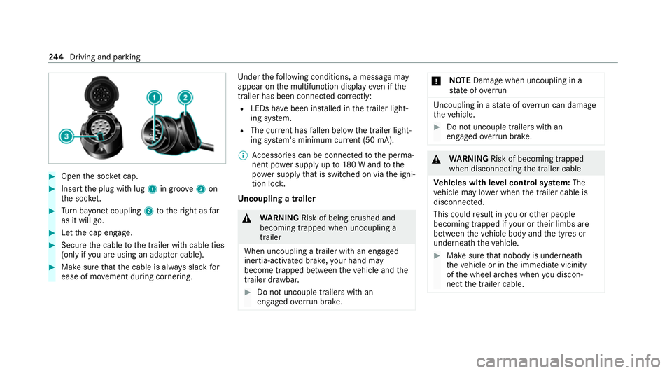
Open the soc ket cap. #
Inse rtthe plug with lug 1in groo ve3 on
th e soc ket. #
Turn bayonet coupling 2totheright as far
as it will go. #
Let the cap engage. #
Secure the cable tothe trailer with cable ties
(only if you are using an adap ter cable). #
Make sure that the cable is alw ays slack for
ease of mo vement during cornering. Under
thefo llowing conditions, a message may
appear on the multifunction display even if the
trailer has been connected cor rectly:
R LEDs ha vebeen ins talled in the trailer light‐
ing sy stem.
R The cur rent has fallen below the trailer light‐
ing sy stem's minimum cur rent (50 mA).
% Accessories can be connected tothe perma‐
nent po wer supp lyup to180 W and tothe
po we r supp lythat is swit ched on via the igni‐
tion loc k.
Un coupling a trailer &
WARNING Risk of being crushed and
becoming trapped when uncoupling a
trailer
When uncoupling a trailer with an engaged
ine rtia-activated brake, your hand may
become trapped between theve hicle and the
trailer dr awbar. #
Do not uncouple trailers with an
engaged overrun brake. *
NO
TEDama gewhen uncoupling in a
st ate of overrun Uncou
pling in a state of overru n can dama ge
th eve hicle. #
Do not uncouple trailers with an
engaged overrun brake. &
WARNING Risk of becoming trapped
when disconnecting the trailer cable
Ve hicles with le vel control sy stem: The
ve hicle may lo wer when the trailer cable is
disconnected.
This could result in you or other people
becoming trapped if your or their limbs are
between theve hicle body and the tyres or
underneath theve hicle. #
Make sure that nobody is unde rneath
th eve hicle or in the immediate vicinity
of the wheel ar ches when you discon‐
nect the trailer cable. 244
Driving and pa rking
Page 253 of 481
7
Selected transmission position
8 Multifunction displ ay(exa mp le:standard dis‐
play for a trip): assi stance / telephone /
navigation / trip / media / radio / styles
and displa ys/ service / possible settings
fo r head-up display
9 Fuel le vel and fuel filler flap location indica‐
tor Overview of buttons on
thest eering wheel 1
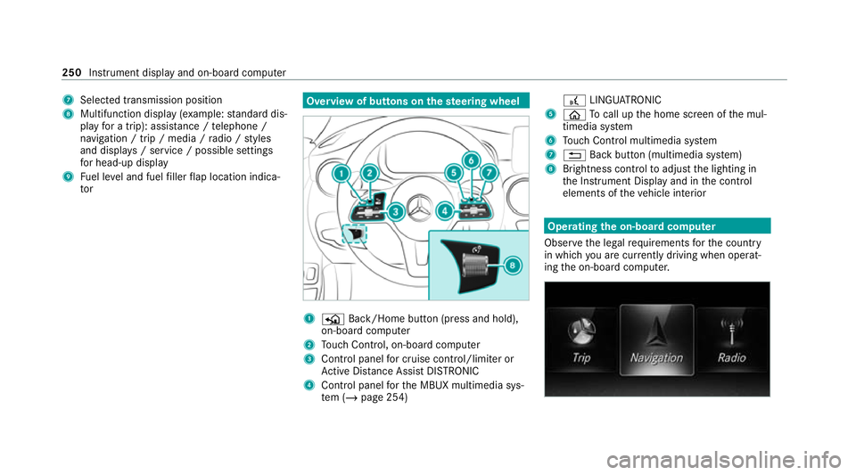
P Back/Home button (press and hold),
on-board computer
2 Touch Control, on-board co mputer
3 Control panel for cruise control/limiter or
Ac tive Dis tance Assi stDISTRONIC
4 Control panel forth e MBUX multimedia sys‐
te m (/ page 254) £
LINGU ATRO NIC
5 ò Tocall up the home screen of the mul‐
timedia sy stem
6 Touch Control multimedia sy stem
7 % Back button (multimedia sy stem)
8 Brightness control toadjust the lighting in
th e Instrument Display and in the control
elements of theve hicle interior Operating
the on-boa rdcompu ter
Obser vethe legal requ irements forth e count ry
in which you are cur rently driving when operat‐
ing the on-board computer. 250
Instrument display and on-board computer
Page 264 of 481
&
WARNING Risk of becoming trapped
du ring adjustment of the driver's seat
af te r calling up a driver profile
Selecting a user profile may trigger an
adju stment of the driver's seat tothe posi‐
tion sa ved under the user profile. You or
ot her vehicle occupants could be injured in
th e process. #
Make sure that when the position of
driver's seat is being adjus ted using the
multimedia sy stem, no people or body
parts are in the seat's range of mo ve‐
ment.
If th ere is a risk of someone becoming trap‐
ped, stop the adjustment process immedi‐
ately: #
a)Tapth ewa rning message on the
media displa y.
or #
b) Press a memory position button or a
seat adjustment switch on the driver's
door.
The adjustment process will be stop‐
ped. The driver's seat is equipped with an access pre‐
ve
nter.
If th e driver's door is open, the driver's seat will
not be set af ter calling up the driver's profile.
Profiles store your vehicle settings and settings
fo rth e multimedia sy stem. If theve hicle is used
by several drivers, the driver can select their
ow n profile wi thout changing thestored profile
settings of other drivers.
% Information on profiles from Mercedes me
connect can be found in the Digital Opera‐
to r's Manual.
Ve hicle settings are, forex ample, driver's seat,
st eering wheel and mir ror settings, clima tecon‐
trol and ambient lighting. Forth e settings of the
multimedia sy stem, you can select, forex ample,
ra dio stations, pr evious destinations as well as
th emes, suggestions and favo urites. Fo
rre cur ring driving situations, su chas long
drives on the mo torw ay,yo u can sa veyour pre‐
fe rred settings in a theme in theve hicle. In a
th eme you can sa vethe display of the digital
map, your prefer redra dio station and prefer red
drive prog ram, forex ample.
The vehicle can learn the habits of the driver. It
th en of fers suggestions forth e most probable
navigation destinations, media sources, radio
st ations or con tacts. The pre-requirements for
th at are the selection of a profile, your consent
to there cording of data and sufficient collected
da ta.
Fa vourites pr ovide quick access toapplications
th at are used of ten. You can select favo urites
from categories or add them directly toan appli‐
cation. MBUX multimedia sy
stem 261