2021 Lexus LC500C AUX
[x] Cancel search: AUXPage 20 of 410

20Pictorial index
■Interior
SRS airbags.................................................................................................................P.2 9
Floor mats ....................................................................................................................P.22
Front seats .................................................................................................................. P. 110
Head restraints ......................................................................................................... P.116
Seat belts ..................................................................................................................... P.24
Console box/auxiliary box... ......................... ........................ .............................. P.247
Cup holder ............................................................................................................... P.247A
B
C
D
E
F
G
Page 248 of 410

2465-5. Using the storage features
5-5.Using the storage features
Glove box (P.246)
Auxiliary net
Door pockets
Console box/auxiliary box
( P.247)
Cup holder ( P.247) 1
Open (press the glove box opener)
2
Unlock with the mechanical key
3
Lock with the mechanical key
■Glove box light
The glove box light turns on when the tail
lights are on.
■Trunk opener main switch
P.103
■If the battery is discharged
The glove box cannot be opened as usual.
Refer to P.333 to open the glove box.
List of storage features
Location of the storage features
WARNING
■Items that should not be left in the
vehicle
Do not leave glasses, lighters or spray
cans in the storage spaces, as this may
cause the following when cabin tempera-
ture becomes high:
●Glasses may be deformed by heat or
cracked if they come into contact with
other stored items.
A
B
C
D
E
●Lighters or spray ca ns may explode. If
they come into contact with other
stored items, the lighter may catch fire
or the spray can may release gas,
causing a fire hazard.
■When storage compartments are not
in use
When driving or when the storage com-
partments are not in use, keep the lids
closed.
In the event of sudden braking or sudden
swerving, an accident may occur due to
an occupant being struck by an open lid
or the items stored inside.
Glove box
Page 249 of 410

2475-5. Using the storage features
5
Interior features
1Using with half-open: Slide the
armrest as far back while pressing
the button.
Press the button to close.
2Using with fully open: Lift the arm-
rest while pulling the knob.
■Console box light
The console box light turns on when the tail
lights are on.
■Using the auxiliary box
Do not place cups, beverage cans, etc. in
the auxiliary box.
To open, press down and release the
cup holder lid.
Console box/auxiliary box
WARNING
■When closing the console box
Take care to prevent your fingers etc.
from being caught.
NOTICE
■To prevent damage to the console
box
●Do not pull the knob while sliding the
armrest.
●Do not apply excessive force to the
armrest.
Cup holder
WARNING
■Items unsuitable for the cup holder
Do not place anything other than a cup
or beverage can in the cup holder. Even
when the lid is closed, items must not be
stored in the cup holder.
Other items may be thrown out of the
holder in the event of an accident or sud-
den braking, causing injury. If possible,
cover hot drinks to prevent burns.
NOTICE
■To prevent damage to the cup holder
and air conditioning control switches
●Do not apply excessive force to the
cup holder.
●Take care when placing a tall bottle in
the cup holder. When the bottle is
taken out or the brakes are suddenly
applied, the bottle may hit the air con-
ditioning control switches, causing
damage to the switches or parts of the
air conditioning system.
Page 274 of 410

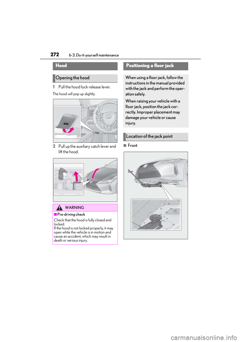
2726-3. Do-it-yourself maintenance
1Pull the hood lock release lever.
The hood will pop up slightly.
2Pull up the auxiliary catch lever and
lift the hood.■Front
Hood
Opening the hood
WARNING
■Pre-driving check
Check that the hood is fully closed and
locked.
If the hood is not locked properly, it may
open while the vehicle is in motion and
cause an accident, which may result in
death or serious injury.
Positioning a floor jack
When using a floor jack, follow the
instructions in the manual provided
with the jack and perform the oper-
ation safely.
When raising your vehicle with a
floor jack, position the jack cor-
rectly. Improper placement may
damage your vehicle or cause
injury.
Location of the jack point
Page 285 of 410

2836-3. Do-it-yourself maintenance
6
Maintenance and care
Tires cannot be rotated.
When run-flat tires are installed, the
vehicle can be driven for a maximum of
100 miles (160 km) at a speed below
50 mph (80 km/h) after any tire goes
flat. (However, the vehicle speed may
not increase to near 50 mph [80
km/h] depending on weather or driv-
ing conditions.)
A run-flat tire has a mark on
the sidewall.
Make sure to replace the flat tire before
the vehicle has been driven for near 100
miles (160 km). Also, do not use a repaired
tire.
■Run-flat tires
●The run-flat tires are for only this vehicle.
Do not use the tires on other vehicles.
●Do not mix run-flat tires and normal tires.
●If non-genuine Lexus wheels are used, it
may be impossible to sufficiently demon-
strate the performanc e of run-flat tires.
Your vehicle is equipped with a tire
pressure warning system that uses tire
pressure warning valves and transmit-
ters to detect low tire inflation pressure
before serious problems arise.
If the tire pressure drops below a
predetermined level, the driver is
warned by a screen display and a
warning light. ( P.319)
The tire pressure detected by the
tire pressure warning system can be
displayed on the multi-information
display. ( P.79)
The illustration used is intended as an
example, and may differ from the image
that is actually displayed on the multi-infor-
mation display.
■Routine tire inflation pressure checks
The tire pressure warning system does not
replace routine tire inflation pressure
checks. Make sure to check tire inflation
pressure as part of your routine of daily
vehicle checks.
■Situations in which the tire pressure
warning system may not operate prop-
erly
●In the following cases, the tire pressure
warning system may not operate prop-
erly.
• If non-genuine Lexus wheels are used.
• A tire has been replaced with a tire that is not an OE (Original Equipment) tire.
• A tire has been replaced with a tire that is not of the specified size.
• Tire chains etc. are equipped.
• An auxiliary-supported run-flat tire is equipped.
• If a window tint that affects the radio wave signals is installed.
• If there is a lot of snow or ice on the vehi- cle, particularly around the wheels or
wheel housings.
• If the tire inflation pressure is extremely higher than the specified level.
• If wheel without tire pressure warning valves and transmitters are used.
Tire rotation
Run-flat tires
Tire pressure warning system
Page 384 of 410

3829-1. For owners
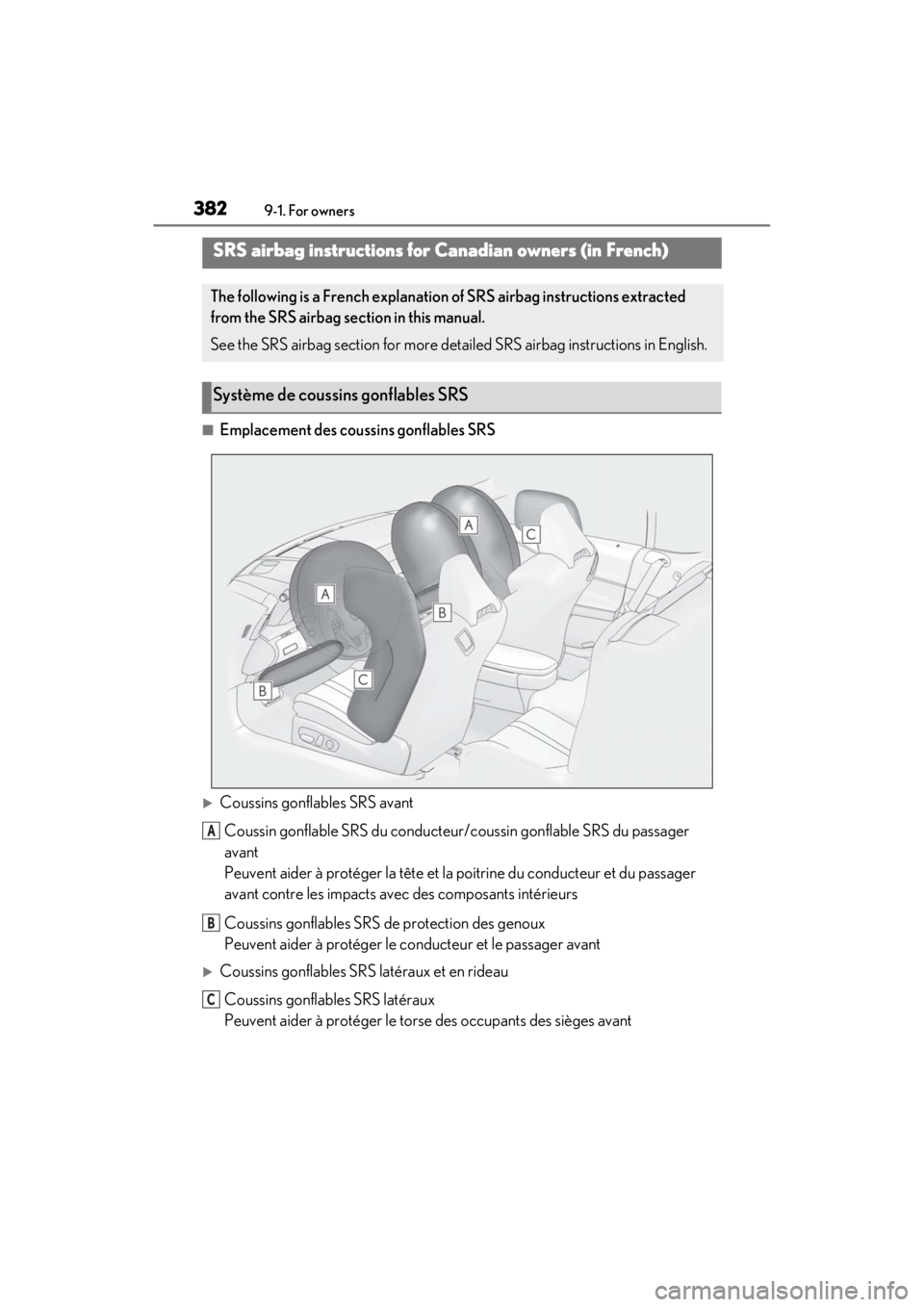
■Emplacement des coussins gonflables SRS
Coussins gonflables SRS avant
Coussin gonflable SRS du conducteur /coussin gonflable SRS du passager
avant
Peuvent aider à protéger la tête et la poitrine du conducteur et du passager
avant contre les impacts avec des composants intérieurs
Coussins gonflables SRS de protection des genoux
Peuvent aider à protéger le co nducteur et le passager avant
Coussins gonflables SRS latéraux et en rideau
Coussins gonflables SRS latéraux
Peuvent aider à protéger le torse des occupants des sièges avant
SRS airbag instructions for Canadian owners (in French)
The following is a French explanation of SRS airbag instructions extracted
from the SRS airbag section in this manual.
See the SRS airbag section for more deta iled SRS airbag instructions in English.
Système de coussins gonflables SRS
A
B
C
Page 385 of 410

3839-1. For owners
9
For owners
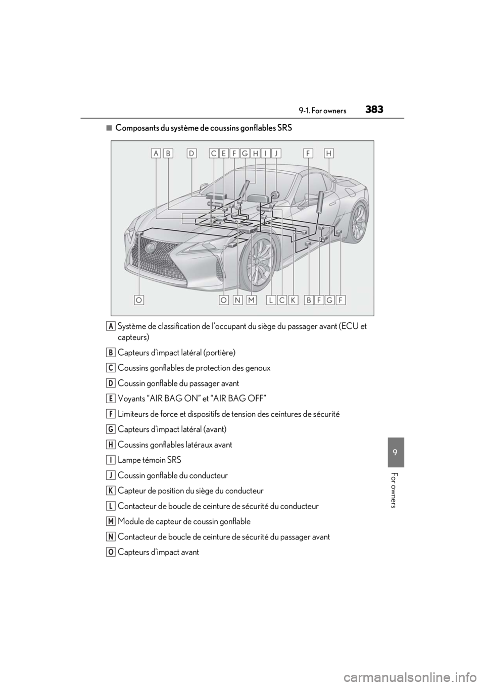
■Composants du système de coussins gonflables SRSSystème de classification de l’occupant du siège du passager avant (ECU et
capteurs)
Capteurs d’impact latéral (portière)
Coussins gonflables de protection des genoux
Coussin gonflable du passager avant
Voyants “AIR BAG ON” et “AIR BAG OFF”
Limiteurs de force et dispositifs de tension des ceintures de sécurit\
é
Capteurs d’impact latéral (avant)
Coussins gonflables latéraux avant
Lampe témoin SRS
Coussin gonflable du conducteur
Capteur de position du siège du conducteur
Contacteur de boucle de ceintu re de sécurité du conducteur
Module de capteur de coussin gonflable
Contacteur de boucle de ceinture de sécurité du passager avant
Capteurs d’impact avant
A
B
C
D
E
F
G
H
I
J
K
L
M
N
O
Page 386 of 410

3849-1. For owners
Votre véhicule est doté de COUSSINS GONFLABLES ÉVOLUÉS dont la con-
ception s’appuie sur les normes de sécurité des véhicules à moteur américains
(FMVSS208). Le module de capteur de coussin gonflable (ECU) contrôle le
déploiement des coussins gonflables en fonction des informations obtenues des
capteurs et d’autres éléments affichés dans le diagramme des\
composants du sys-
tème ci-dessus. Ces informations compre nnent des données relatives à la gravité
de l’accident et aux occupants. Au moment du déploiement des coussins gonfla-
bles, une réaction chimique se produit dans les gonfleurs de coussin gonflable et
les coussins gonflables se remplissent rapidement d’un gaz non toxique pour aider
à limiter le mouvement des occupants.
AVERTISSEMENT
■Précautions relatives aux coussins
gonflables SRS
Observez les précautions suivantes en
ce qui concerne les coussins gonflables
SRS.
Les négliger pourrait occasionner des
blessures graves, voire mortelles.
●Le conducteur et tous les passagers
du véhicule doivent porter leur cein-
ture de sécurité de la manière appro-
priée.
Les coussins gonflables SRS sont des
dispositifs supplémentaires qui doivent
être utilisés avec les ceintures de sécu-
rité.
●Le coussin gonflable SRS du conduc-
teur se déploie avec une force con-
sidérable et peut occasionner des
blessures graves, voire mortelles,
notamment lorsque le conducteur se
trouve très près du coussin gonflable.
La National Highway Traffic Safety
Administration (NHTSA), aux États-
Unis, fait les recommandations
suivantes :
La zone à risque du coussin gonflable
du conducteur couvre 2 à 3 in. (50 à
75 mm) de la zone de déploiement du
coussin gonflable. Pour assurer une
marge de sécurité su ffisante, restez à
10 in. (250 mm) du coussin gonflable.
Cette distance est mesurée depuis le
centre du volant jusqu’à votre sternum.
Si maintenant vous vous tenez assis à
moins de 10 in. (250 mm), vous pou-
vez changer votre position de con-
duite de plusieurs manières :
• Reculez votre siège à la position maxi- male vous permettant d’atteindre
encore aisément les pédales.