Page 525 of 667

Emergency towing precautions
Turn the ignition switch to ACC so
the steering wheel isn’t locked.
Place the transmission shift lever in
N (Neutral).
Release the parking bake.
Press the brake pedal with more
force than normal since you will
have reduced brake performance.
More steering effort will be
required because the power steer-
ing system will be disabled.
If you are driving down a long hill,
the brakes may overheat and brake
performance will be reduced. Stop
often and let the brakes cool off.
The vehicle should be towed at a
speed of 25 km/h (15 mph) or less
within the distance of 20 km (12
miles). If the car is being towed with all
four wheels on the ground, it can
be towed only from the front. Be
sure that the transmission is in N
(Neutral). Be sure the steering is
unlocked by placing the ignition
switch in the ACC position. A driver
must be in the towed vehicle to
operate the steering and brakes.
CAUTION - Dual clutch
transmission
To avoid serious damage to the
dual clutch transmission, limit
the vehicle speed to 15 km/h
(10 mph) and drive less than
1.5 km (1 mile) when towing.
Before towing, check the dual
clutch transmission for fluid
leaks under your vehicle. If the
dual clutch transmission fluid
is leaking, flatbed equipment
or a towing dolly must be
used.
What to do in an emergency
43 6
Page 585 of 667

759
Maintenance
✽ ✽
NOTICE
• When replacing fuse, turn the
ignition “OFF” and turn off
switches of all electrical devices
then remove battery (-) terminal.
• The actual fuse/relay panel label
may differ from equipped items.
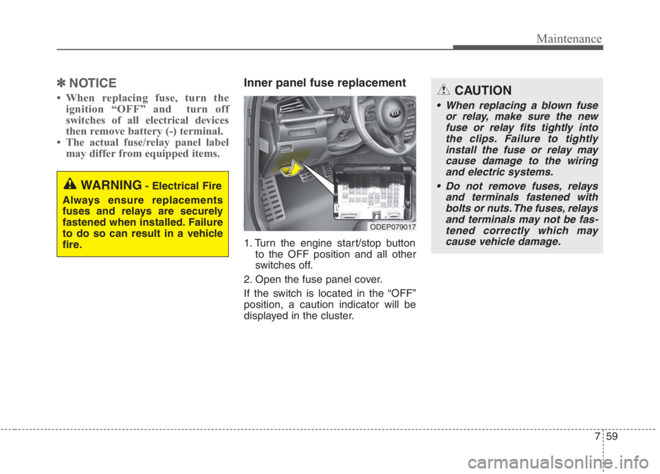
Inner panel fuse replacement
1. Turn the engine start/stop button
to the OFF position and all other
switches off.
2. Open the fuse panel cover.
If the switch is located in the “OFF”
position, a caution indicator will be
displayed in the cluster.
WARNING- Electrical Fire
Always ensure replacements
fuses and relays are securely
fastened when installed. Failure
to do so can result in a vehicle
fire.
CAUTION
When replacing a blown fuse
or relay, make sure the new
fuse or relay fits tightly into
the clips. Failure to tightly
install the fuse or relay may
cause damage to the wiring
and electric systems.
Do not remove fuses, relays
and terminals fastened with
bolts or nuts. The fuses, relays
and terminals may not be fas-
tened correctly which may
cause vehicle damage.
ODEP079017
Page 601 of 667
775
Maintenance
Engine room compartment fuse panel (Hybrid)
Fuse NameFuse ratingCircuit Protected
MULTI FUSE
B+ 560AFuse - BATTERY C/FAN, HORN, ECU2, Engine Control Relay
B+ 260AInstrument Panel Junction Block (Fuse - S/HEATER (REAR))
B+ 360AInstrument Panel Junction Block
B+ 450AInstrument Panel Junction Block (Fuse - BATTERY MANAGEMENT, P/WINDOW (LH), P/WIN-
DOW (RH), TAIL GATE OPEN, SUNROOF, AMP, S/HEATER (FRT), P/SEAT (DRV))
COOLING FAN60ACooling Fan Relay
REAR HEATED50ARear Heated Relay
BLOWER40ABlower Relay
IG 140A[Without Smart Key] Ignition Switch, [With Smart Key] PDM1 (ACC) Relay, PDM2 (IG1) Relay
IG 240A[Without Smart Key] Ignition Switch, [With Smart Key] PDM3 (IG2) Relay
MDPS80AMDPS (Motor Driven Power Steering) Unit
PTC
HEATER 150APTC Heater 1 Relay
PTC
HEATER 250APTC Heater 2 Relay
CLUTCH
ACTUATOR40AClutch Actuator (HEV)
MAIN150AFuse - H/LAMP HI, INVERTER, ACTIVE HYDRAULIC BOOSTER1, ACTIVE HYDRAULIC
BOOSTER2, WIPER RR, EPB1, EPB2
Page 604 of 667
Maintenance
78 7
Fuse NameFuse ratingCircuit Protected
FUSE
SENSOR 115AOxygen Sensor (Up), Oxygen Sensor (Down)
IGN COIL20AIgnition Coil #1/#2/#3/#4
ECU 215AECM (Engine Control Module)
Page 605 of 667
779
Maintenance
Engine room compartment fuse panel (Plug-in Hybrid)
Fuse NameFuse ratingCircuit Protected
MULTI FUSE
B+ 560AFuse - BATTERY C/FAN, HORN, ECU2, Engine Control Relay
B+ 260AInstrument Panel Junction Block (Fuse - S/HEATER (REAR))
B+ 360AInstrument Panel Junction Block
B+ 450AInstrument Panel Junction Block (Fuse - BATTERY MANAGEMENT, P/WINDOW (LH), P/WIN-
DOW (RH), TAIL GATE OPEN, SUNROOF, AMP, S/HEATER (FRT), P/SEAT (DRV), IG3 1,
OBC, AMS)
COOLING FAN60ACooling Fan Relay
REAR HEATED50ARear Heated Relay
BLOWER40ABlower Relay
IG 140A[Without Smart Key] Ignition Switch, [With Smart Key] PDM1 (ACC) Relay, PDM2 (IG1) Relay
IG 240A[Without Smart Key] Ignition Switch, [With Smart Key] PDM3 (IG2) Relay
MDPS80AMDPS (Motor Driven Power Steering) Unit
PTC
HEATER 150APTC Heater 1 Relay
PTC
HEATER 250APTC Heater 2 Relay
CLUTCH
ACTUATOR40AClutch Actuator (PHEV)
MAIN150AFuse - H/LAMP HI, INVERTER, ACTIVE HYDRAULIC BOOSTER1, ACTIVE HYDRAULIC
BOOSTER2, WIPER RR, EPB1, EPB2
Page 608 of 667
Maintenance
82 7
Fuse NameFuse ratingCircuit Protected
FUSE
SENSOR 115AOxygen Sensor (Up), Oxygen Sensor (Down)
IGN COIL20AIgnition Coil #1/#2/#3/#4
ECU 215AECM (Engine Control Module)
Page 643 of 667

7117
Maintenance
Your vehicle is equipped with a cat-
alytic converter emission control
device.
Therefore, the following precautions
must be observed:
Use only UNLEADED FUEL for
gasoline engines.
Do not operate the vehicle when
there are signs of engine malfunc-
tion, such as misfire or a noticeable
loss of performance.
Do not misuse or abuse the
engine. Examples of misuse are
coasting with the ignition off and
descending steep grades in gear
with the ignition off.
Do not operate the engine at high
idle speed for extended periods (5
minutes or more).
Do not modify or tamper with any
part of the engine or emission con-
trol system. All inspections and
adjustments must be made by an
authorized Kia dealer.
Avoid driving with an extremely low
fuel level. Running out of fuel could
cause the engine to misfire, dam-
aging the catalytic converter.Failure to observe these precautions
could result in damage to the catalyt-
ic converter and to your vehicle.
Additionally, such actions could void
your warranties.
Page 662 of 667

Index
6I
Instrument cluster . . . . . . . . . . . . . . . . . . . . . . . . . . . . . 4-66
Dual clutch transmission shift indicator . . . . . . . . . 4-74
Gauges . . . . . . . . . . . . . . . . . . . . . . . . . . . . . . . . . . . 4-68
Instrument cluster control . . . . . . . . . . . . . . . . . . . . 4-68
Instrument panel overview . . . . . . . . . . . . . . . . . . . . . . . 2-5
Interior features. . . . . . . . . . . . . . . . . . . . . . . . . . . . . . 4-167
AC inverter . . . . . . . . . . . . . . . . . . . . . . . . . . . . . . . 4-172
Air ventilation seat . . . . . . . . . . . . . . . . . . . . . . . . . 4-169
Cargo security screen . . . . . . . . . . . . . . . . . . . . . . . 4-179
Clothes hanger . . . . . . . . . . . . . . . . . . . . . . . . . . . . 4-177
Cup holder . . . . . . . . . . . . . . . . . . . . . . . . . . . . . . . 4-167
Floor mat anchor(s) . . . . . . . . . . . . . . . . . . . . . . . . 4-177
Luggage net holder. . . . . . . . . . . . . . . . . . . . . . . . . 4-178
Power outlet . . . . . . . . . . . . . . . . . . . . . . . . . . . . . . 4-170
Seat warmer . . . . . . . . . . . . . . . . . . . . . . . . . . . . . . 4-167
Sunvisor . . . . . . . . . . . . . . . . . . . . . . . . . . . . . . . . . 4-170
USB charger . . . . . . . . . . . . . . . . . . . . . . . . . . . . . . 4-171
Wireless smart phone charging system . . . . . . . . . 4-173
Interior lights . . . . . . . . . . . . . . . . . . . . . . . . . . . . . . . 4-140
Automatic turn off function . . . . . . . . . . . . . . . . . . 4-140
Liftgate room lamp. . . . . . . . . . . . . . . . . . . . . . . . . 4-142
Map lamp . . . . . . . . . . . . . . . . . . . . . . . . . . . . . . . . 4-140
Room lamp . . . . . . . . . . . . . . . . . . . . . . . . . . . . . . . 4-141
Vanity mirror lamp . . . . . . . . . . . . . . . . . . . . . . . . . 4-142
Interior overview. . . . . . . . . . . . . . . . . . . . . . . . . . . . . . . 2-4Key positions . . . . . . . . . . . . . . . . . . . . . . . . . . . . . . . . . 5-7
Ignition switch position . . . . . . . . . . . . . . . . . . . . . . . 5-7
Illuminated ignition switch . . . . . . . . . . . . . . . . . . . . 5-7
Starting the hybrid system . . . . . . . . . . . . . . . . . . . . . 5-9
Lane Following Assist (LFA) . . . . . . . . . . . . . . . . . . . 5-125
LFA system malfunction . . . . . . . . . . . . . . . . . . . . 5-129
LFA system operation . . . . . . . . . . . . . . . . . . . . . . 5-126
Limitation of the system . . . . . . . . . . . . . . . . . . . . 5-130
Lane Keeping Assist (LKA) . . . . . . . . . . . . . . . . . . . . . 5-70
Lane Keeping Assist system malfunction . . . . . . . . 5-76
LKA activation . . . . . . . . . . . . . . . . . . . . . . . . . . . . . 5-73
LKA system operation . . . . . . . . . . . . . . . . . . . . . . . 5-72
System setting . . . . . . . . . . . . . . . . . . . . . . . . . . . . . 5-72
LCD display . . . . . . . . . . . . . . . . . . . . . . . . . . . . . . . . . 4-76
LCD display control . . . . . . . . . . . . . . . . . . . . . . . . . 4-76
LCD display modes . . . . . . . . . . . . . . . . . . . . . . . . . 4-77
Trip modes (Trip computer) . . . . . . . . . . . . . . . . . . . 4-89
Warning messages . . . . . . . . . . . . . . . . . . . . . . . . . . 4-94
Liftgate . . . . . . . . . . . . . . . . . . . . . . . . . . . . . . . . . . . . . 4-26
Closing the liftgate . . . . . . . . . . . . . . . . . . . . . . . . . . 4-26
Emergency liftgate safety release. . . . . . . . . . . . . . . 4-27
Opening the liftgate . . . . . . . . . . . . . . . . . . . . . . . . . 4-26K
L