Page 324 of 482

5-108
Driving your vehicle
To temporarily accelerate with
the Smart Cruise Control on
If you want to speed up temporarily
when the Smart Cruise Control is on,
depress the accelerator pedal.
Increased speed will not interfere
with Smart Cruise Control operation
or change the set speed.
To return to the set speed, take your
foot off the accelerator pedal.
If you push the toggle switch down
(SET-) at increased speed, the cruis-
ing speed will be set again pedal.
Smart Cruise Control set speed
will be temporarily canceled
when:
Canceled manually
Depressing the brake pedal.
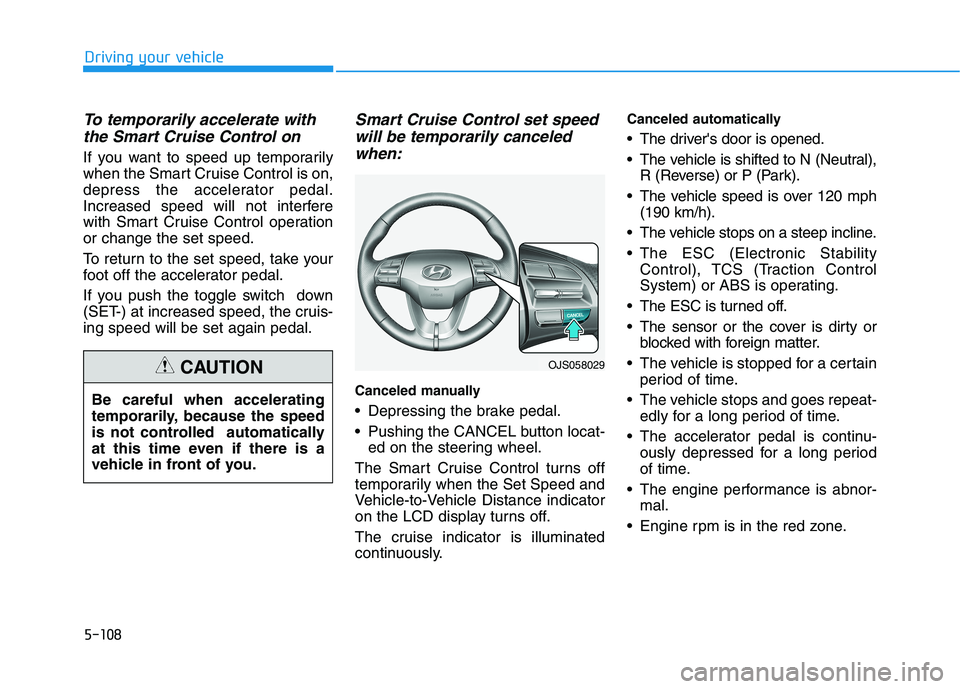
Pushing the CANCEL button locat-
ed on the steering wheel.
The Smart Cruise Control turns off
temporarily when the Set Speed and
Vehicle-to-Vehicle Distance indicator
on the LCD display turns off.
The cruise indicator is illuminated
continuously.
Canceled automatically
The driver's door is opened.
The vehicle is shifted to N (Neutral),
R (Reverse) or P (Park).
The vehicle speed is over 120 mph
(190 km/h).
The vehicle stops on a steep incline.
The ESC (Electronic Stability
Control), TCS (Traction Control
System) or ABS is operating.
The ESC is turned off.
The sensor or the cover is dirty or
blocked with foreign matter.
The vehicle is stopped for a certain
period of time.
The vehicle stops and goes repeat-
edly for a long period of time.
The accelerator pedal is continu-
ously depressed for a long period
of time.
The engine performance is abnor-
mal.
Engine rpm is in the red zone.
OJS058029
Be careful when accelerating
temporarily, because the speed
is not controlled automatically
at this time even if there is a
vehicle in front of you.
CAUTION
Page 416 of 482

7-37
7
Maintenance
T TI
IR
RE
ES
S
A
AN
ND
D
W
WH
HE
EE
EL
LS
S
Tire Care
For proper maintenance, safety, and
maximum fuel economy, you must
always maintain recommended tire
inflation pressures and stay within
the load limits and weight distribution
recommended for your vehicle.
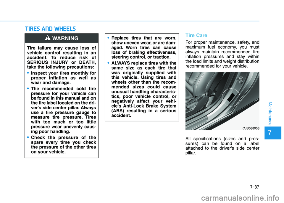
All specifications (sizes and pres-
sures) can be found on a label
attached to the driver's side center
pillar.Replace tires that are worn,
show uneven wear, or are dam-
aged. Worn tires can cause
loss of braking effectiveness,
steering control, or traction.
ALWAYS replace tires with the
same size as each tire that
was originally supplied with
this vehicle. Using tires and
wheels other than the recom-
mended sizes could cause
unusual handling characteris-
tics, poor vehicle control, or
negatively affect your vehi-
cle's Anti-Lock Brake System
(ABS) resulting in a serious
accident.
Tire failure may cause loss of
vehicle control resulting in an
accident. To reduce risk of
SERIOUS INJURY or DEATH,
take the following precautions:
Inspect your tires monthly for
proper inflation as well as
wear and damage.
The recommended cold tire
pressure for your vehicle can
be found in this manual and on
the tire label located on the dri-
ver's side center pillar. Always
use a tire pressure gauge to
measure tire pressure. Tires
with too much or too little
pressure wear unevenly caus-
ing poor handling.
Check the pressure of the
spare every time you check
the pressure of the other tires
on your vehicle.
WARNING
OJS088003
Page 420 of 482

7-41
7
Maintenance
Tire Replacement
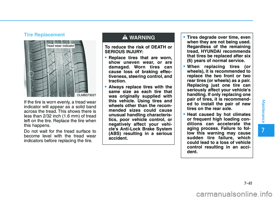
If the tire is worn evenly, a tread wear
indicator will appear as a solid band
across the tread. This shows there is
less than 2/32 inch (1.6 mm) of tread
left on the tire. Replace the tire when
this happens.
Do not wait for the tread surface to
become level with the tread wear
indicators before replacing the tire.
OLMB073027
Tread wear indicatorTo reduce the risk of DEATH or
SERIOUS INJURY:
Replace tires that are worn,
show uneven wear, or are
damaged. Worn tires can
cause loss of braking effec-
tiveness, steering control, and
traction.
Always replace tires with the
same size as each tire that
was originally supplied with
this vehicle. Using tires and
wheels other than the recom-
mended sizes could cause
unusual handling characteris-
tics, poor vehicle control, or
negatively affect your vehi-
cle's Anti-Lock Brake System
(ABS) resulting in a serious
accident.
WARNING Tires degrade over time, even
when they are not being used.
Regardless of the remaining
tread, HYUNDAI recommends
that tires be replaced after six
(6) years of normal service.
When replacing tires (or
wheels), it is recommended to
replace the two front or two
rear tires (or wheels) as a pair.
Replacing just one tire can
seriously affect your vehicle's
handling. If only replacing one
pair of tires, it is recommend-
ed to install the pair of new
tires on the rear axle.
Heat caused by hot climates
or frequent high loading con-
ditions can accelerate the
aging process. Failure to fol-
low this warning may cause
sudden tire failure, which
could lead to a loss of vehicle
control resulting in an acci-
dent.
Page 438 of 482
7-59
7
Maintenance
Fuse NameFuse RatingProtected Component
START7.5ATransaxle Range Switch (DCT), ECM, Ignition Lock & Clutch Switch,
E/R Junction Block (START #1 Relay, B/Alarm Relay),
Smart Key Control Module
CLUSTER7.5AHead Up Display, Instrument Cluster
DOOR LOCK20AICM Relay Box (Twoturn Unlock Relay)
PDM37.5AStart Stop Button Switch, Immobilizer Module
FCA10AForward Collision Avoidance Assist Unit
S/HEATER20AFront Seat Warmer Module
A/C210A-
A/C17.5AA/C Control Module, E/R Junction Block (Blower Relay)
PDM115ASmart Key Control Module
SPARE-Spare
AIR BAG15ASRS Control Module, Passenger Occupant Detection
IG125APCB Block(FUSE : ECU5, VACUUM PUMP, ABS3, TCU2)
Instrument panel fuse panel
Page 441 of 482
7-62
Maintenance
Engine compartment fuse panel
Fuse NameFuse RatingProtected Component
ALT150AAlternator, E/R Junction Block (Fuse - MDPS, B/ALARM HORN, ABS1, ABS2)
MDPS80AMDPS Unit
B+560APCB Block ((Fuse - ECU4, ECU3, HORN, A/CON COMP (G4NH)), Engine Control Relay)
B+260AIGPM ((Fuse - S/HEATER), IPS0, IPS1, IPS2)
B+360AIGPM (IPS3, IPS4, IPS5, IPS6)
B+450AIGPM (Fuse - P/WINDOW LH/RH, TAILGATE OPEN, SUNROOF1/2, AMP, P/SEAT(DRV))
COOLING
FAN160AE/R Junction Block (C/Fan2 Hi Relay) (G4FJ)
REAR
HEATED40AE/R Junction Block (Rear Heated Relay)
BLOWER40AE/R Junction Block (Blower Relay)
IG140AW/O Smark Key : Ignition Switch
With Smark Key : E/R Junction Block (PDM #2 Relay (ACC), PDM #3 Relay (IG1))
IG240AW/O Smark Key : E/R Junction Block (START #1 Relay), Ignition Switch
With Smark Key : E/R Junction Block (START #1 Relay, PDM #4 Relay (IG2))
[G4FJ] : 1.6 T-GDI
[G4NH] : 2.0 MPI
Page 442 of 482
7-63
7
Maintenance
Engine compartment fuse panel
Fuse NameFuse RatingProtected Component
FUEL PUMP20AE/R Junction Block (Fuel Pump Relay)
VACUUM
PUMP120AVacuum Pump
TCU115ATCM
COOLING
FAN240AE/R Junction Block (C/Fan1 Low Relay, C/Fan2 Hi Relay) (G4NH)
B+140AIGPM ((Fuse - BRAKE SWITCH, PDM1, PDM3, MODULE1, DOOR LOCK), Leak Current Autocut Device)
DCT140ATCM
DCT240ATCM
B/ALARM
HORN15AE/R Junction Block (B/ALARM Horn Relay)
ABS140AESC Module, ABS Control Module, Multipurpose Check Connector
ABS230AESC Module, ABS Control Module
[G4FJ] : 1.6 T-GDI
[G4NH] : 2.0 MPI
Page 444 of 482
7-65
7
Maintenance
Fuse NameFuse RatingProtected Component
ABS310AABS Control Module, ESC Module, Multipurpose Check Connector
TCU215ATransmission Range Switch(A/T), TCM (With DCT)
SENSOR310AE/R Junction Block (F/PUMP Relay)
ECU415AECM/PCM
HORN15AHorn Relay
Engine compartment fuse panel
[G4FJ] : 1.6 T-GDI
[G4NH] : 2.0 MPI
Page 448 of 482
![HYUNDAI VELOSTER 2021 Owners Manual 7-69
7
Maintenance
[1] : High beam, [2] : Low beam
Headlamp
1. Open the hood.
2. Disconnect the negative battery
cable.
3. Remove the headlamp bulb cover
by turning it counterclockwise.
4. Disconnect HYUNDAI VELOSTER 2021 Owners Manual 7-69
7
Maintenance
[1] : High beam, [2] : Low beam
Headlamp
1. Open the hood.
2. Disconnect the negative battery
cable.
3. Remove the headlamp bulb cover
by turning it counterclockwise.
4. Disconnect](/manual-img/35/41165/w960_41165-447.png)
7-69
7
Maintenance
[1] : High beam, [2] : Low beam
Headlamp
1. Open the hood.
2. Disconnect the negative battery
cable.
3. Remove the headlamp bulb cover
by turning it counterclockwise.
4. Disconnect the headlamp bulb
socket-connector.5. Remove the bulb from the head-
lamp assembly.
6. Install a new headlamp bulb and
snap the headlamp bulb retaining
wire into position by aligning the
wire with the groove on the bulb.
7. Connect the headlamp bulb sock-
et-connector.
8. Install the headlamp bulb cover by
turning it clockwise.
Information
The headlamp aiming should be
adjusted after an accident or after the
headlamp assembly is reinstalled at an
authorized HYUNDAI dealer.
Turn signal
1. Open the hood.
2. Disconnect the negative battery
cable.
3. Remove the socket (1) from the
assembly by turning the socket
counterclockwise until the tabs on
the socket align with the slots on
the assembly.
4. Remove the bulb from the socket
by pressing it in and rotating it
counterclockwise until the tabs on
the bulb align with the slots in the
socket. Pull the bulb out of the
socket.
iOJS078028OJS078027 ■High/Low beam