2021 HYUNDAI TUCSON park assist
[x] Cancel search: park assistPage 306 of 546
5-40
Driving your vehicle
VSM OFF condition
To cancel VSM operation, press the
ESC OFF button. ESC OFF indicator
light ( ) will illuminate.
To turn on VSM, press the ESC OFF
button again. The ESC OFF indicator
light will go out.
Driving with wheels and tires with dif-
ferent sizes may cause the ESC sys-
tem to malfunction. Before replacing
tires, make sure all four tires and
wheels are the same size. Never
drive the vehicle with different sized
tires and wheels installed.
Hill-Start Assist Control (HAC)
The Hill-Start Assist Control (HAC)
helps prevent the vehicle from rolling
backwards when starting a vehicle
from a stop on a hill. The system
operates the brakes automatically for
approximately 2 seconds and releas-
es the brake after 2 seconds or when
the accelerator pedal is depressed.
The HAC does not operate when
the shift lever is in P (Park) or N
(Neutral)
The HAC activates even though
the ESC (Electronic Stability
Control) is off but does not acti-
vate when the ESC has malfunc-
tioned.
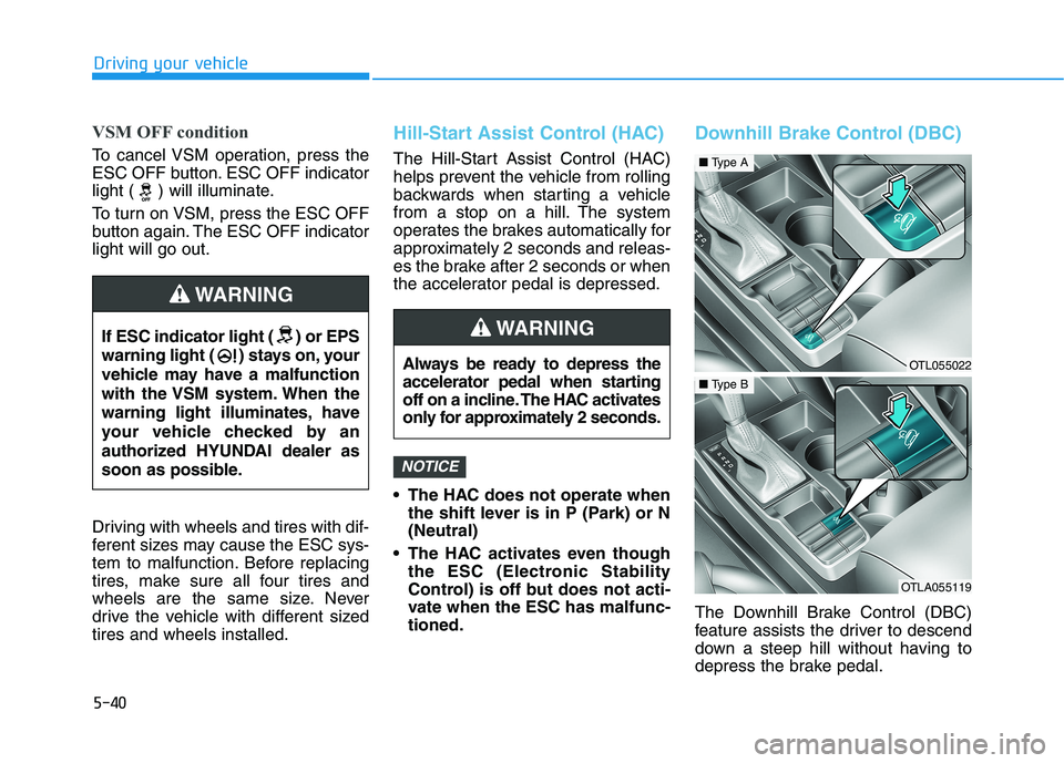
Downhill Brake Control (DBC)
The Downhill Brake Control (DBC)
feature assists the driver to descend
down a steep hill without having to
depress the brake pedal.
NOTICE
If ESC indicator light ( ) or EPS
warning light ( ) stays on, your
vehicle may have a malfunction
with the VSM system. When the
warning light illuminates, have
your vehicle checked by an
authorized HYUNDAI dealer as
soon as possible.
WARNING
Always be ready to depress the
accelerator pedal when starting
off on a incline. The HAC activates
only for approximately 2 seconds.
WARNING
OTL055022
■Type A
OTLA055119
■Type B
Page 308 of 546
5-42
Driving your vehicle
The DBC may not deactivate on
steep inclines even though the
brake or accelerator pedal is
depressed.
The DBC does not operate
when:
- The shift lever is in P (Park).
- The ESC is activated.
Good Braking Practices
Wet brakes can be dangerous! The
brakes may get wet if the vehicle is
driven through standing water or if it
is washed. Your vehicle will not stop
as quickly if the brakes are wet. Wet
brakes may cause the vehicle to pull
to one side.To dry the brakes, apply the brakes
lightly until the braking action returns
to normal, taking care to keep the
vehicle under control at all times. If
the braking action does not return to
normal, stop as soon as it is safe to
do so and call an authorized
HYUNDAI dealer for assistance.
DO NOT drive with your foot resting
on the brake pedal. Even light, but
constant pedal pressure can result in
the brakes overheating, brake wear,
and possibly even brake failure.
If a tire goes flat while you are driv-
ing, apply the brakes gently and
keep the vehicle pointed straight
ahead while you slow down. When
you are moving slowly enough for it
to be safe to do so, pull off the road
and stop in a safe location.
Keep your foot firmly on the brake
pedal when the vehicle is stopped to
prevent the vehicle from rolling for-
ward.
NOTICE
If the DBC red indicator light
illuminates, the system may
have overheated or have mal-
functioned. When the warning
light illuminates even though
the DBC system has cooled off,
have your vehicle checked by
an authorized HYUNDAI dealer
as soon as possible.
WARNING
Whenever leaving the vehicle or
parking, always come to a com-
plete stop and continue to
depress the brake pedal. Move
the shift lever into the P (Park)
position, then apply the parking
brake, and place the ignition
switch in the OFF position.
Vehicles parked with the park-
ing brake not applied or not
fully engaged may roll inadver-
tently and may cause injury to
the driver and others. ALWAYS
apply the parking brake before
exiting the vehicle.
WARNING
Page 334 of 546
5-68
Driving your vehicle
Limitations of the System
The Forward Collision-Avoidance
Assist (FCA) system is designed to
help monitor the vehicle ahead in the
roadway through camera recognition
to warn the driver that a collision is
imminent, and if necessary, apply
emergency braking.
In certain situations, the camera may
not be able to detect the vehicle
ahead. In these cases, the FCA sys-
tem may not operate normally. The
driver must pay careful attention in
the following situations where the
FCA operation may be limited.Occupants may get injured, if
the vehicle abruptly stops by
the activated FCA system. Pay
extreme caution.
The FCA system operates
only to help detect vehicles in
front of the vehicle.
The FCA system does not
operate when the vehicle is in
reverse.
The FCA system is not
designed to detect other
objects on the road such as
animals.
The FCA system does not
detect vehicles in the oppo-
site lane.
The FCA system does not
detect cross traffic vehicles
that are approaching.
The FCA system cannot
detect the driver approaching
the side view of a parked vehi-
cle (for example on a dead
end street.)
In these cases, you must main-
tain a safe braking distance,
and if necessary, depress the
brake pedal to reduce the driv-
ing speed in order to maintain a
safe distance.
WARNING
Page 347 of 546
5-81
Driving your vehicle
5
Limitations of the System
The Forward Collision-Avoidance
Assist (FCA) system is designed to
help monitor the vehicle ahead or a
pedestrian in the roadway through
radar signals and camera recognition
to warn the driver that a collision is
imminent, and if necessary, apply
emergency braking.
In certain situations, the radar sen-
sor or the camera may not be able to
detect the vehicle or pedestrian
ahead. In these cases, the FCA sys-
tem may not operate normally. The
driver must pay careful attention in
the following situations where the
FCA operation may be limited.
Detecting vehicles
The sensor may be limited when:
The radar sensor or camera is
blocked with a foreign object or
debris
The camera lens is contaminated
due to tinted, filmed or coated
windshield, damaged glass, or
stuck of foreign matter (sticker,
bug, etc.) on the glass
Inclement weather such as heavy
rain or snow obscures the field of
view of the radar sensor or camera
There is interference by electro-
magnetic waves
The vehicle is on unpaved or
uneven rough surfaces, or road
with sudden gradient changes.
The vehicle drives through a con-
struction area, on an unpaved
road, or above metal materials,
such as a railway
The radar/camera sensor recogni-
tion is limited
The vehicle in front is too small to
be detected (for example a motor-
cycle or a bicycle, etc.)The FCA system cannot
detect the driver approaching
the side view of a parked vehi-
cle (for example on a dead
end street.)
In these cases, you must main-
tain a safe braking distance,
and if necessary, depress the
brake pedal to reduce the driv-
ing speed in order to maintain a
safe distance.
Page 414 of 546
6-5
What to do in an emergency
6
Information
An inappropriately disposedbattery can be harmful to the
environment and human
health. Dispose the battery
according to your local law(s)
or regulations.
To prevent damage to your vehi-
cle:
• Only use a 12-volt power supply (battery or jumper system) to
jump start your vehicle.
Do not attempt to jump start your vehicle by push-starting.
Jump starting procedure
1. Position the vehicles close enough that the jumper cables will reach,
but do not allow the vehicles to
touch.
2. Avoid fans or any moving parts in the engine compartment at all
times, even when the vehicles are
turned off.
3. Turn off all electrical devices such as radios, lights, air conditioning,
etc. Put the vehicles in P (Park)
and set the parking brakes. Turn
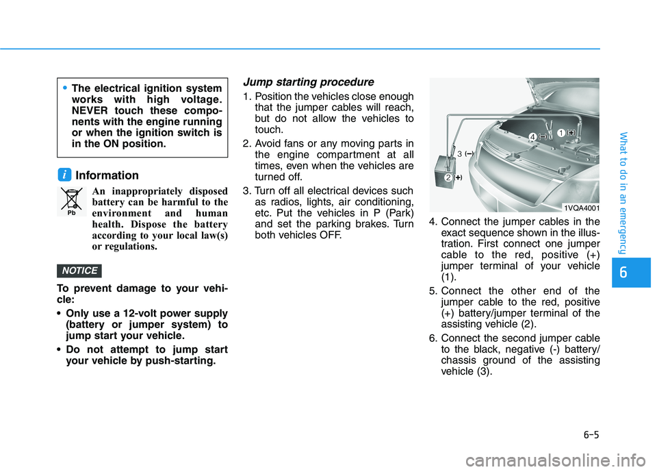
both vehicles OFF. 4. Connect the jumper cables in the
exact sequence shown in the illus-
tration. First connect one jumper
cable to the red, positive (+)
jumper terminal of your vehicle
(1).
5. Connect the other end of the jumper cable to the red, positive
(+) battery/jumper terminal of the
assisting vehicle (2).
6. Connect the second jumper cable to the black, negative (-) battery/
chassis ground of the assisting
vehicle (3).
NOTICE
i
Pb
The electrical ignition system
works with high voltage.
NEVER touch these compo-
nents with the engine running
or when the ignition switch is
in the ON position.
1VQA4001
Page 415 of 546
6-6
I IF
F
T
TH
HE
E
E
EN
NG
GI
IN
NE
E
O
OV
VE
ER
RH
HE
EA
AT
TS
S
What to do in an emergency
7. Connect the other end of the sec-
ond jumper cable to the black,
negative (-) chassis ground of
your vehicle (4).
Do not allow the jumper cables to
contact anything except the cor-
rect battery or jumper terminals or
the correct ground. Do not lean
over the battery when making
connections.
8. Start the engine of the assisting
vehicle and let it run at approxi-
mately 2,000 rpm for a few min-
utes. Then start your vehicle.
If your vehicle will not start after a
few attempts, it probably requires
servicing. In this event please seek
qualified assistance. If the cause of
your battery discharging is not
apparent, have your vehicle checked
by an authorized HYUNDAI dealer.Disconnect the jumper cables in the
exact reverse order you connected
them:
1. Disconnect the jumper cable from
the black, negative (-) chassis
ground of your vehicle (4).
2. Disconnect the other end of the
jumper cable from the black, neg-
ative (-) battery/chassis ground of
the assisting vehicle (3).
3. Disconnect the second jumper
cable from the red, positive (+)
battery/jumper terminal of the
assisting vehicle (2).
4. Disconnect the other end of the
jumper cable from the red, positive
(+) jumper terminal of your vehicle
(1).If your temperature gauge indicates
overheating, you experience a loss
of power, or hear loud pinging or
knocking, the engine may be over-
heating. If this happens, you should:
1. Pull off the road and stop as soon
as it is safe to do so.
2. Place the shift lever in P (Park)
and set the parking brake. If the air
conditioning is ON, turn it OFF.
3. If engine coolant is running out
under the vehicle or steam is com-
ing out from the hood, stop the
engine. Do not open the hood until
the coolant has stopped running
or the steaming has stopped. If
there is no visible loss of engine
coolant and no steam, leave the
engine running and check to be
sure the engine cooling fan is
operating. If the fan is not running,
turn the engine off.
Page 491 of 546
7
Maintenance
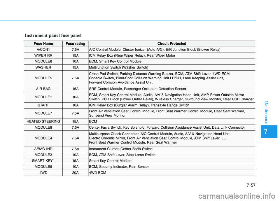
Instrument panel fuse panel
Fuse Name Fuse ratingCircuit Protected
A/CON1 7.5AA/C Control Module, Cluster Ionizer (Auto A/C), E/R Junction Block (Blower Relay)
WIPER RR 15AICM Relay Box (Rear Wiper Relay), Rear Wiper Motor
MODULE6 10ABCM, Smart Key Control Module
WASHER 15AMultifunction Switch (Washer Switch)
MODULE5 7.5ACrash Pad Switch, Parking Distance Warning Buzzer, BCM, ATM Shift Lever, 4WD ECM,
Console Switch, Blind-Spot Collision Warning Unit LH/RH, Lane Keeping Assist Unit,
Forward Collision Avoidance Assist Unit
AIR BAG 15ASRS Control Module, Passenger Occupant Detection Sensor
MODULE1 10ABCM, Smart Key Control Module, Audio, A/V & Navigation Head Unit, AMP, Power Outside Mirror
Switch, PCB Block (Power Outlet Relay), Wireless Charger, Surround View Monitor, Rear USB Charger
START 10AICM Relay Box (Burglar Alarm Relay), Transaxle Range Switch
MODULE7 7.5AFront Air Ventilation Seat Control Module, Front Seat Warmer Control Module, Rear Seat Warmer,
Surround View Monitor
HEATED STEERING 15ABCM
MODULE8 7.5ACenter Facia Switch, Key Solenoid, Forward Collision Avoidance Assist Unit, Data Link Connector
MODULE4 7.5AMultipurpose Check Connector, A/C Control Module, Audio, A/V & Navigation Head Unit,
Electro Chromic Mirror, Front Air Ventilation Seat Control Module, ATM Shift Lever ILL.,
Front Seat Warmer Control Module, Rear Seat Warmer
A/BAG IND 7.5AInstrument Cluster, Center Facia Switch
MODULE310ABCM, ATM Shift Lever, Stop Lamp Switch
SMART KEY115ASmart Key Control Module
MODULE910ABCM, Security Indicator, Rain Sensor
4WD20A4WD ECM
7-57
Page 538 of 546
I-3
Brake Fluid .....................................................................7-23
Checking the Brake Fluid Level ................................7-23
Braking System ...............................................................5-21
Anti-lock Brake System (ABS)..................................5-33
Auto Hold ...................................................................5-30
Disc Brakes Wear Indicator........................................5-22
Downhill Brake Control (DBC) .................................5-40
Electronic Parking Brake (EPB) ................................5-24
Electronic Stability Control (ESC).............................5-35
Good Braking Practices..............................................5-42
Hill-Start Assist Control (HAC) .................................5-40
Parking Brake .............................................................5-22
Power Brakes..............................................................5-21
Vehicle Stability Management (VSM) .......................5-39
Bulb Wattage .....................................................................8-4
California Perchlorate Notice .........................................7-87
Cargo Net Holder ..........................................................3-167
Cargo Security Screen ..................................................3-167
Center Console Storage ................................................3-157
Child Restraint System (CRS) ........................................2-38
Children Always in the Rear ......................................2-38
Installing a Child Restraint System (CRS) ................2-41
Selecting a Child Restraint System (CRS).................2-39Climate Control Additional Features ............................3-156
Automatic Ventilation...............................................3-156
Cluster ionizer ..........................................................3-156
Sunroof Inside Air Recirculation .............................3-156
Climate Control Air Filter...............................................7-27
Filter Inspection..........................................................7-27
Clock .............................................................................3-165
Clothes Hanger .............................................................3-165
Consumer Information ....................................................8-13
Cruise Control ...............................................................5-100
Cruise Control operation ..........................................5-100
Cup Holder....................................................................3-159
Curtain air bags ...............................................................2-53
Declaration of conformity .............................................5-59
The radio frequency components
(Rear Corner Radar) complies: ..................................5-59
Dimensions .......................................................................8-2
Disc Brakes Wear Indicator ............................................5-22
Door Locks .....................................................................3-15
Automatic Door Lock and Unlock Features ..............3-18
Child-Protector Rear Door locks................................3-19
Operating Door Locks from Inside the Vehicle .........3-16
Operating Door Locks from Outside the Vehicle ......3-15
Downhill Brake Control (DBC) .....................................5-40
Drive Mode Integrated Control System .........................5-51
I
Index
C
D