Page 596 of 636
Maintenance
9-46
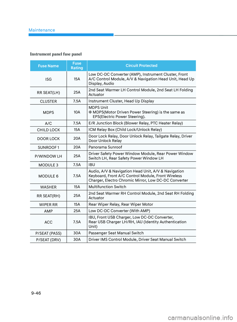
Instrument panel fuse panel
Fuse NameFuse
Rating Circuit Protected
ISG 15ALow DC-DC Converter (AMP), Instrument Cluster, Front
A/C Control Module, A/V & Navigation Head Unit, Head Up
Display, Audio
RR SEAT(LH) 25A2nd Seat Warmer LH Control Module, 2nd Seat LH Folding
Actuator
CLUSTER 7.5A Instrument Cluster, Head Up Display
MDPS 10AMDPS Unit
❈
MDPS(Mo
tor Driven Power Steering) is the same as
EPS(Electric Power Steering).
A/C 7.5A E/R Junction Block (Blower Relay, PTC Heater Relay)
CHILD LOCK 15A ICM Relay Box (Child Lock/Unlock Relay)
DOOR LOCK 20ADoor Lock Relay, Door Unlock Relay, Tailgate Relay, Driver
Door Unlock Relay
SUNROOF 1 20A
Panorama Sunroof
P/WINDOW LH 25ADriver Safety Power Window Module, Rear Power Window
Switch LH, Rear Safety Power Window LH
MODULE 3 7.5A IBU
MODULE 6 7.5AAudio, A/V & Navigation Head Unit, A/V & Navigation
Keyboard, Front A/C Control Module, Front Wireless
Charger, Electro Chromic Mirror, Low DC-DC Converter
WASHER 15A Multifunction Switch
RR SEAT(RH) 25A2nd Seat Warmer RH Control Module, 2nd Seat RH Folding
Actuator
WIPER RR 15A Rear Wiper Relay, Rear Wiper Motor
AMP 25A Low DC-DC Converter (With AMP)
ACC 7.5AIBU, Front USB Charger, Low DC-DC Converter,
Rear USB Charger LH/RH, IAU (Identity Authentication
Unit)
P/SEAT (PASS) 30A
Passenger Seat Manual Switch
P/SEAT (DRV) 30A
Driver IMS Control Module, Driver Seat Manual Switch
Page 597 of 636
09
9-47
Engine compartment fuse panel
(Engine room junction block)
OTMA090014
Inside the fuse/relay box cover, you can
find the fuse/relay label describing fuse/
relay names and ratings.
Information
Not all fuse panel descriptions in this
manual may be applicable to your vehicle;
the information is accurate at the time of
printing. When you inspect the fuse panel
in your vehicle, refer to the fuse panel
label.
OTMA090025
Page 598 of 636
![HYUNDAI SANTA FE 2021 Owners Manual Maintenance
9-48
Engine compartment fuse panel (Engine room junction block)
Type Fuse NameFuse
Rating Circuit Protected
MULTI
FUSE 1 (10P) COOLING FAN1
80A
[BLDC 600W] Cooling Fan Controller
COOLIN HYUNDAI SANTA FE 2021 Owners Manual Maintenance
9-48
Engine compartment fuse panel (Engine room junction block)
Type Fuse NameFuse
Rating Circuit Protected
MULTI
FUSE 1 (10P) COOLING FAN1
80A
[BLDC 600W] Cooling Fan Controller
COOLIN](/manual-img/35/41163/w960_41163-597.png)
Maintenance
9-48
Engine compartment fuse panel (Engine room junction block)
Type Fuse NameFuse
Rating Circuit Protected
MULTI
FUSE 1 (10P) COOLING FAN1
80A
[BLDC 600W] Cooling Fan Controller
COOLING FAN2 60A
[BLDC 400W] Cooling Fan Controller
B+4 50AICU Junction Block (Fuse - MODULE8,
SUNROOF1, AMP, P/WINDOW RH, S/HEATER
DRV/PASS)
B+2 50AICU Junction Block (IPS 8 SPOC+/IPS 10/IPS 11/
IPS 13/IPS 14/IPS 15)
B+3 50AICU Junction Block (Fuse - E-SHIFTER1, P/
SEAT (DRV, P/SEAT (PASS), P/WINDOW LH, RR
SEAT(LH))
BLOWER 40A
Blower Relay
IG2 40A
Start Relay, PCB Block (PDM (IG2) Relay)
ABS 2 30A
ESC Module
MULTI
FUSE 2 (10P) MDPS
100A MDPS Unit
ABS 3 60A
ESC Module
B+6 60A
PCB Block (B+)
DCT 60A
TCM
E-CVVT1 50A
PCB Block (E-CVVT Relay)
REAR HEATED 40A
Rear Heated Relay
INVERTER 40A
AC Inverter Module
E-SHIFTER 1 40A
SCU
FUSE HEATED
MIRROR 10A
Rear Heated Relay, Driver/Passenger Outside
Mirror, Front A/C Control Module
E-CVVT3 20A
PCM, PCB Block (E-CVVT Relay)
E-CVVT2 20A
PCM, PCB Block (E-CVVT Relay)
A/C2 10A
Blower Relay, Front A/C Control Module
VACUUM PUMP2 10A
ESC Module, Vacuum Pump Relay, Vacuum Pump
B+5 50AICU Junction Block (Fuse - DOOR LOCK,
IBU1, IBU2, BRAKE SWITCH, CHILD LOCK, RR
SEAT(RH), SUNROOF2)
EOP2 60A
[G4KP] Electronic Oil Pump
Page 599 of 636
09
9-49
Engine compartment fuse panel (Engine room junction block)
Type Fuse NameFuse
Rating Circuit Protected
FUSE B+1
50AICU Junction Block (IPS 1 SPOC+/IPS 2/IPS 3/IPS
5/IPS 6/IPS 7/Long Term Load Latch Relay, Short
Term Load Latch Relay)
PTC HEATER 50APTC Heater Relay
TRAILER3 30ATrailer Module
POWER TAIL GATE 30A
Power Tail Gate Unit
TRAILER2 30ATrailer Module
FUEL PUMP 20AFuel Pump Relay
AMS 10ABattery Sensor
VACUUM PUMP1 20AVacuum Pump Relay
4WD 20A4WD ECM
E-SHIFTER2 10ASCU
TRAILER1 30ATrailer Module
Page 600 of 636
Maintenance
9-50
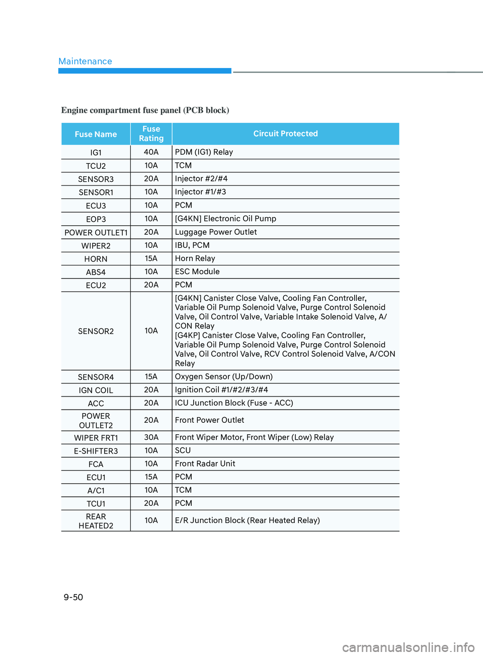
Engine compartment fuse panel (PCB block)
Fuse NameFuse
Rating Circuit Protected
IG1 40A
PDM (IG1) Relay
TCU2 10A
TCM
SENSOR3 20A
Injector #2/#4
SENSOR1 10A
Injector #1/#3
ECU3 10A
PCM
EOP3 10A
[G4KN] Electronic Oil Pump
POWER OUTLET1 20A
Luggage Power Outlet
WIPER2 10A
IBU, PCM
HORN 15A Horn Relay
ABS4 10A
ESC Module
ECU2 20A
PCM
SENSOR2 10A[G4KN] Canister Close Valve, Cooling Fan Controller,
Variable Oil Pump Solenoid Valve, Purge Control Solenoid
Valve, Oil Control Valve, Variable Intake Solenoid Valve, A/
CON Relay
[G4KP] Canister Close Valve, Cooling Fan Controller,
Variable Oil Pump Solenoid Valve, Purge Control Solenoid
Valve, Oil Control Valve, RCV Control Solenoid Valve, A/CON
Relay
SENSOR4 15A Oxygen Sensor (Up/Down)
IGN COIL 20A
Ignition Coil #1/#2/#3/#4
ACC 20A
ICU Junction Block (Fuse - ACC)
POWER
OUTLET2 20A
Front Power Outlet
WIPER FRT1 30A
Front Wiper Motor, Front Wiper (Low) Relay
E-SHIFTER3 10A
SCU
FCA 10A
Front Radar Unit
ECU1 15A PCM
A/C1 10A
TCM
TCU1 20A
PCM
REAR
HEATED2 10A
E/R Junction Block (Rear Heated Relay)
Page 603 of 636
09
9-53
OTM090035
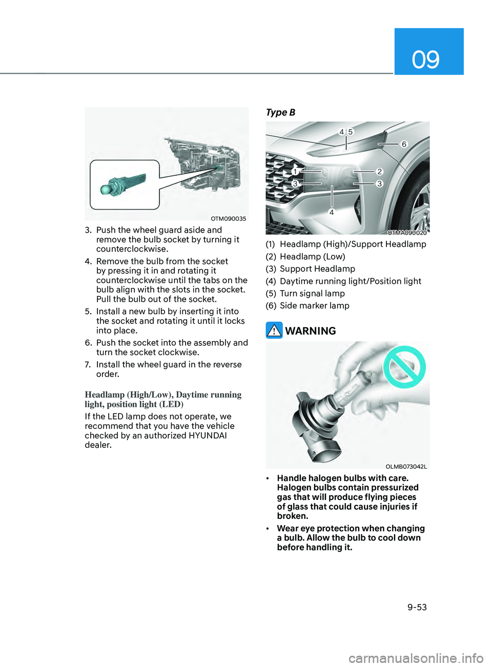
3. Push the wheel guard aside and
remove the bulb socket by turning it
counterclockwise.
4.
Remo
ve the bulb from the socket
by pressing it in and rotating it
counterclockwise until the tabs on the
bulb align with the slots in the socket.
Pull the bulb out of the socket.
5.
Install a ne
w bulb by inserting it into
the socket and rotating it until it locks
into place.
6.
Push the socke
t into the assembly and
turn the socket clockwise.
7.
Install the wheel guar
d in the reverse
order.
Headlamp (High/Low), Daytime running
light, position light (LED)
If the LED lamp does not operate, we
recommend that you have the vehicle
checked by an authorized HYUNDAI
dealer.
Type B
OTMA090020
(1) Headlamp (High)/Support Headlamp
(2)
Headlamp (L
ow)
(3)
Support Headlamp
(4
)
Daytime running ligh
t/Position light
(5)
Turn signal lamp
(
6)
Side marker lamp
WARNING
OLMB073042L
• Handle halogen bulbs with care.
Halogen bulbs contain pressurized
gas that will produce flying pieces
of glass that could cause injuries if
broken.
• Wear eye protection when changing
a bulb. Allow the bulb to cool down
before handling it.
Page 604 of 636
Maintenance
9-54
• Always handle them carefully, and
avoid scratches and abrasions. If
the bulbs are lit, avoid contact with
liquids.
• Never touch the glass with bare
hands. Residual oil may cause the
bulb to overheat and burst when lit.
• A bulb should be operated only when
installed in a headlamp.
• If a bulb becomes damaged or
cracked, replace it immediately and
carefully dispose of it.
Lamps
If the LED lamp does not operate, we
recommend that you have the vehicle
checked by an authorized HYUNDAI
dealer.
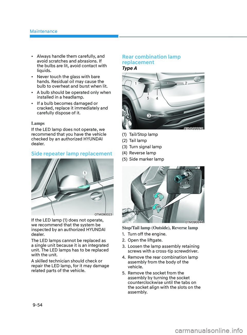
Side repeater lamp replacement
OTM090023
If the LED lamp (1) does not operate,
we recommend that the system be
inspected by an authorized HYUNDAI
dealer.
The LED lamps cannot be replaced as
a single unit because it is an integrated
unit. The LED lamps has to be replaced
with the unit.
A skilled technician should check or
repair the LED lamp, for it may damage
related parts of the vehicle.
Rear combination lamp
replacement
Type A
OTMA090021
(1) Tail/Stop lamp
(2)
Tail lamp
(3
)
Turn signal lamp
(4
)
Re
verse lamp
(5)
Side marker lamp
OTM090044
Stop/Tail lamp (Outside), Reverse lamp
1.
Turn o
ff the engine.
2.
Open the liftga
te.
3.
Loosen the lamp assembly r
etaining
screws with a cross-tip screwdriver.
4.
Remo
ve the rear combination lamp
assembly from the body of the
vehicle.
5.
Remo
ve the socket from the
assembly by turning the socket
counterclockwise until the tabs on
the socket align with the slots on the
assembly.
Page 605 of 636
09
9-55
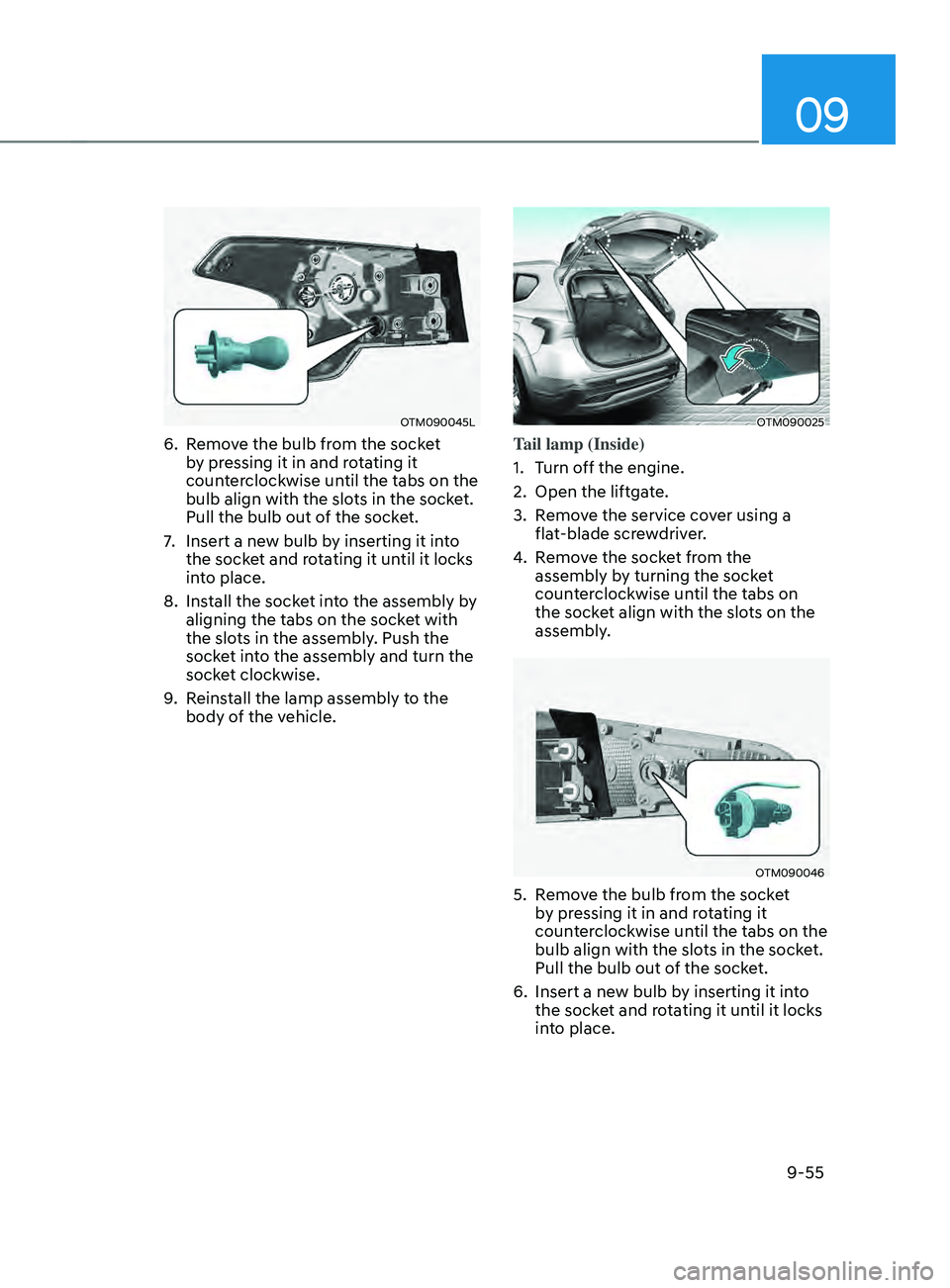
OTM090045L
6. Remove the bulb from the socket
by pressing it in and rotating it
counterclockwise until the tabs on the
bulb align with the slots in the socket.
Pull the bulb out of the socket.
7.
Insert a new bulb b
y inserting it into
the socket and rotating it until it locks
into place.
8.
Install the sock
et into the assembly by
aligning the tabs on the socket with
the slots in the assembly. Push the
socket into the assembly and turn the
socket clockwise.
9.
Reins
tall the lamp assembly to the
body of the vehicle.
OTM090025
Tail lamp (Inside)
1.
Turn o
ff the engine.
2.
Open the liftga
te.
3.
Remo
ve the service cover using a
flat-blade screwdriver.
4.
Remo
ve the socket from the
assembly by turning the socket
counterclockwise until the tabs on
the socket align with the slots on the
assembly.
OTM090046
5. Remove the bulb from the socket
b y pressing it in and rotating it
counterclockwise until the tabs on the
bulb align with the slots in the socket.
Pull the bulb out of the socket.
6.
Insert a new bulb b
y inserting it into
the socket and rotating it until it locks
into place.