2021 HYUNDAI SANTA FE CALLIGRAPHY battery
[x] Cancel search: batteryPage 581 of 636

09
9-31
• The negative battery cable must
be removed first and installed last
when the battery is disconnected.
Disconnect the battery charger in the
following order:
1.
Turn o
ff the battery charger main
switch.
2.
Unhook the nega
tive clamp from
the negative battery terminal.
3.
Unhook the positiv
e clamp from
the positive battery terminal.
• We recommend that you use
batteries for replacement from an
authorized HYUNDAI dealer.
NOTICE
AGM battery (if equipped)
• Absorbent Glass Matt (AGM)
batteries are maintenance-free
and we recommend that the AGM
battery be serviced by an authorized
HYUNDAI dealer. For charging
your AGM battery, use only fully
automatic battery chargers that
are specially developed for AGM
batteries.
• When replacing the AGM battery,
we recommend that you use parts
for replacement from an authorized
HYUNDAI dealer.
• Do not open or remove the cap on
top of the battery. This may cause
leaks of internal electrolyte that
could result in severe injury.
By jump starting
After a jump start from a good battery,
drive the vehicle for 20-30 minutes
before it is shutoff. The vehicle may
not restart if you shut it off before the
battery had a chance to adequately
recharge. See “Jump Starting” in chapter
6 for more information on jump starting
procedures.
Information
An inappropriately disposed
battery can be harmful to the
environment and human health.
Dispose of the battery according
to your local law(s) or regulation.
Reset items
The following items may need to be reset
after the battery has been discharged or
the battery has been disconnected.
• Auto up/down window (see chapter 5)
• Sunroof (see chapter 5)
• Trip computer (see chapter 5)
• Climate control system (see chapter 5)
• Driver position memory system (see
chapter 5)
• Clock (see chapter 5)
• Infotainment system (see
infotainment system manual)
Page 591 of 636

09
9-41
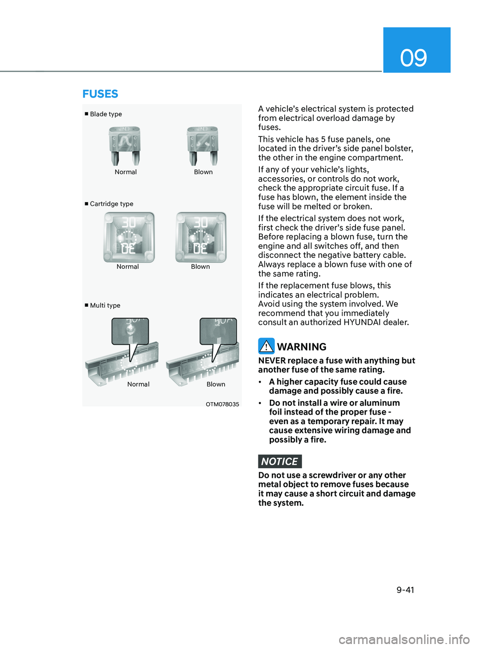
■ Blade type
■ Cartridge type
■ Multi type Normal
Blown
Normal Blown
Normal Blown
OTM078035
A vehicle’s electrical system is protected
from electrical overload damage by
fuses.
This vehicle has 5 fuse panels, one
located in the driver’s side panel bolster,
the other in the engine compartment.
If any of your vehicle’s lights,
accessories, or controls do not work,
check the appropriate circuit fuse. If a
fuse has blown, the element inside the
fuse will be melted or broken.
If the electrical system does not work,
first check the driver’s side fuse panel.
Before replacing a blown fuse, turn the
engine and all switches off, and then
disconnect the negative battery cable.
Always replace a blown fuse with one of
the same rating.
If the replacement fuse blows, this
indicates an electrical problem.
Avoid using the system involved. We
recommend that you immediately
consult an authorized HYUNDAI dealer.
WARNING
NEVER replace a fuse with anything but
another fuse of the same rating.
• A higher capacity fuse could cause
damage and possibly cause a fire.
• Do not install a wire or aluminum
foil instead of the proper fuse -
even as a temporary repair. It may
cause extensive wiring damage and
possibly a fire.
NOTICE
Do not use a screwdriver or any other
metal object to remove fuses because
it may cause a short circuit and damage
the system.
FUSES
Page 599 of 636

09
9-49
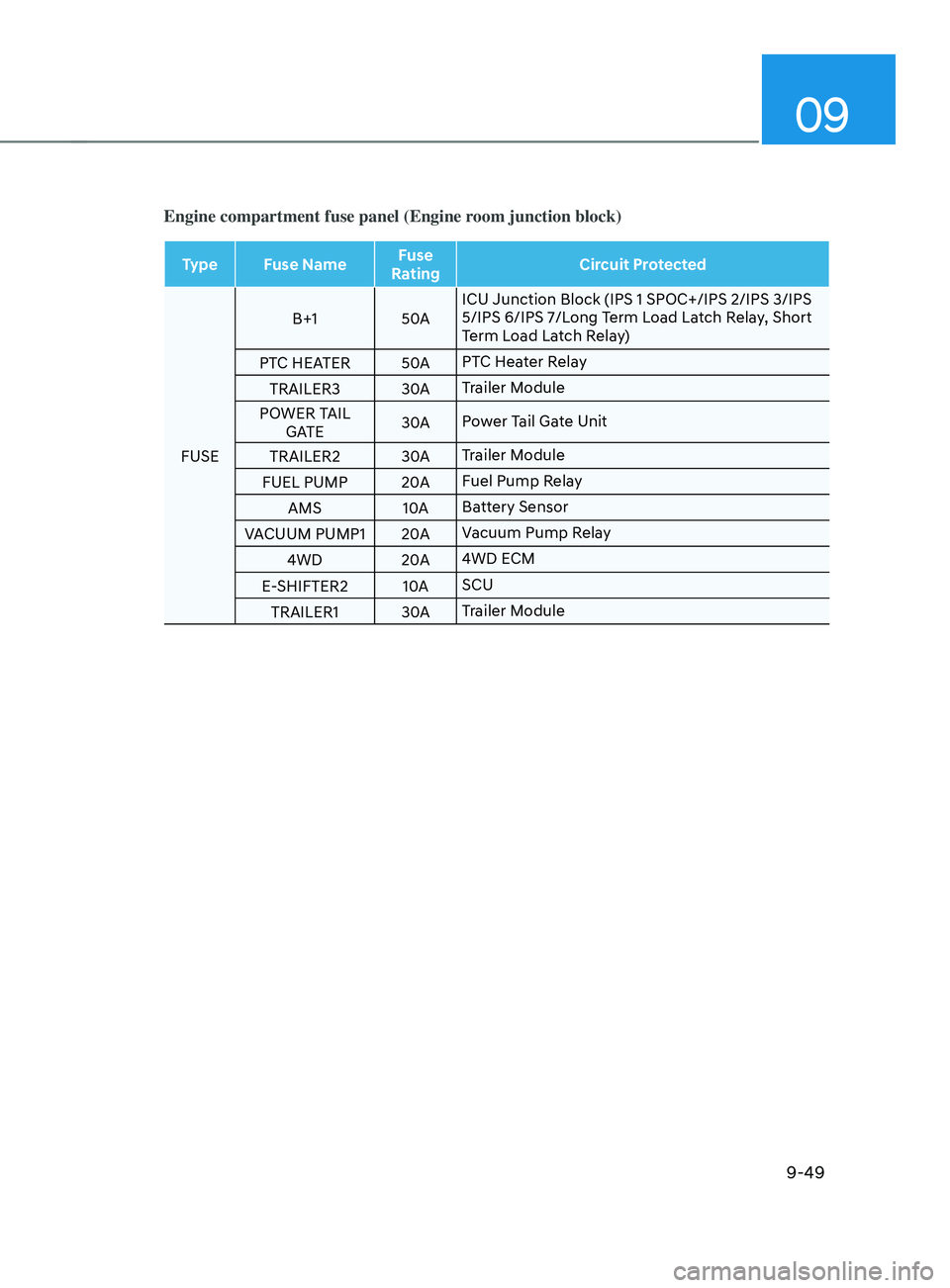
Engine compartment fuse panel (Engine room junction block)
Type Fuse NameFuse
Rating Circuit Protected
FUSE B+1
50AICU Junction Block (IPS 1 SPOC+/IPS 2/IPS 3/IPS
5/IPS 6/IPS 7/Long Term Load Latch Relay, Short
Term Load Latch Relay)
PTC HEATER 50APTC Heater Relay
TRAILER3 30ATrailer Module
POWER TAIL GATE 30A
Power Tail Gate Unit
TRAILER2 30ATrailer Module
FUEL PUMP 20AFuel Pump Relay
AMS 10ABattery Sensor
VACUUM PUMP1 20AVacuum Pump Relay
4WD 20A4WD ECM
E-SHIFTER2 10ASCU
TRAILER1 30ATrailer Module
Page 602 of 636

Maintenance
9-52
Information
• A normally functioning lamp may
flicker momentarily to stabilize the
vehicle’s electrical control system.
However, if the lamp goes out after
flickering momentarily, or continues to
flicker, we recommend the system be
checked by an authorized HYUNDAI
dealer.
• The position lamp may not turn on
when the position lamp switch is turned
on, but the position lamp and headlamp
switch may turn on when the headlamp
switch is turned on. This may be caused
by network failure or vehicle electrical
control system malfunction. If this
occurs, we recommend the system be
checked by an authorized HYUNDAI
dealer.
Information
The headlamp aiming should be adjusted
after an accident or after the headlamp
assembly is reinstalled.
Information
Traffic Change (For Europe)
The low beam light distribution is
asymmetric. If you go abroad to a country
with opposite traffic direction, this
asymmetric part will dazzle oncoming car
driver. To prevent dazzle, ECE regulation
demand several technical solutions (ex.
automatic change system, adhesive
sheet, down aiming). This headlamps are
designed not to dazzle opposite drivers. So,
you need not change your headlamps in a
country with opposite traffic direction.
Headlamp, position lamp, turn
signal lamp, Daytime Running
Light (DRL) replacement
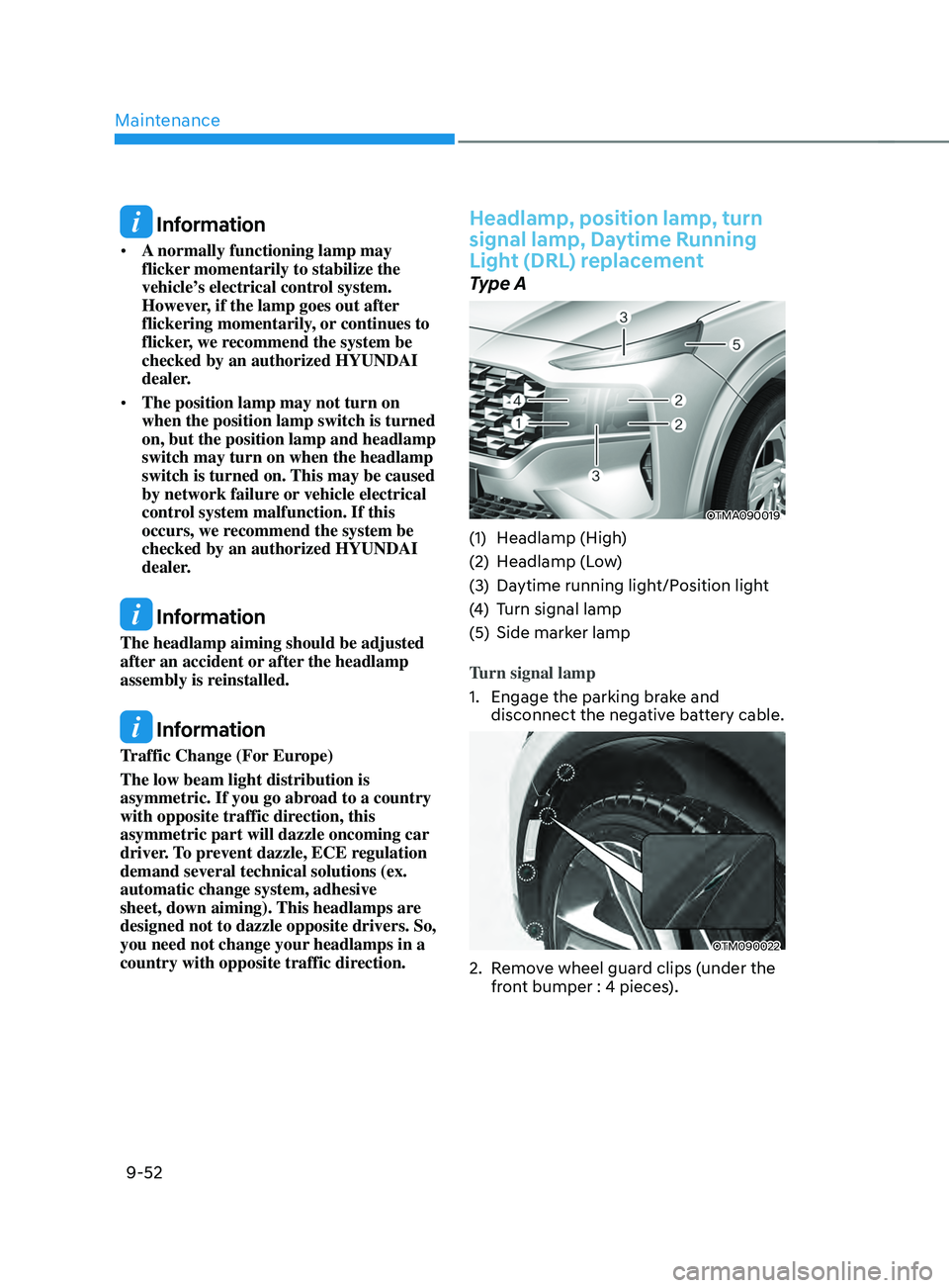
Type A
OTMA090019
(1) Headlamp (High)
(2)
Headlamp (L
ow)
(3)
Daytime running ligh
t/Position light
(4)
Turn signal lamp
(5)
Side marker lamp
T
urn signal lamp
1.
Engage the parking br
ake and
disconnect the negative battery cable.
OTM090022
2. Remove wheel guard clips (under the
fr ont bumper : 4 pieces).
Page 625 of 636

I
I-3
B
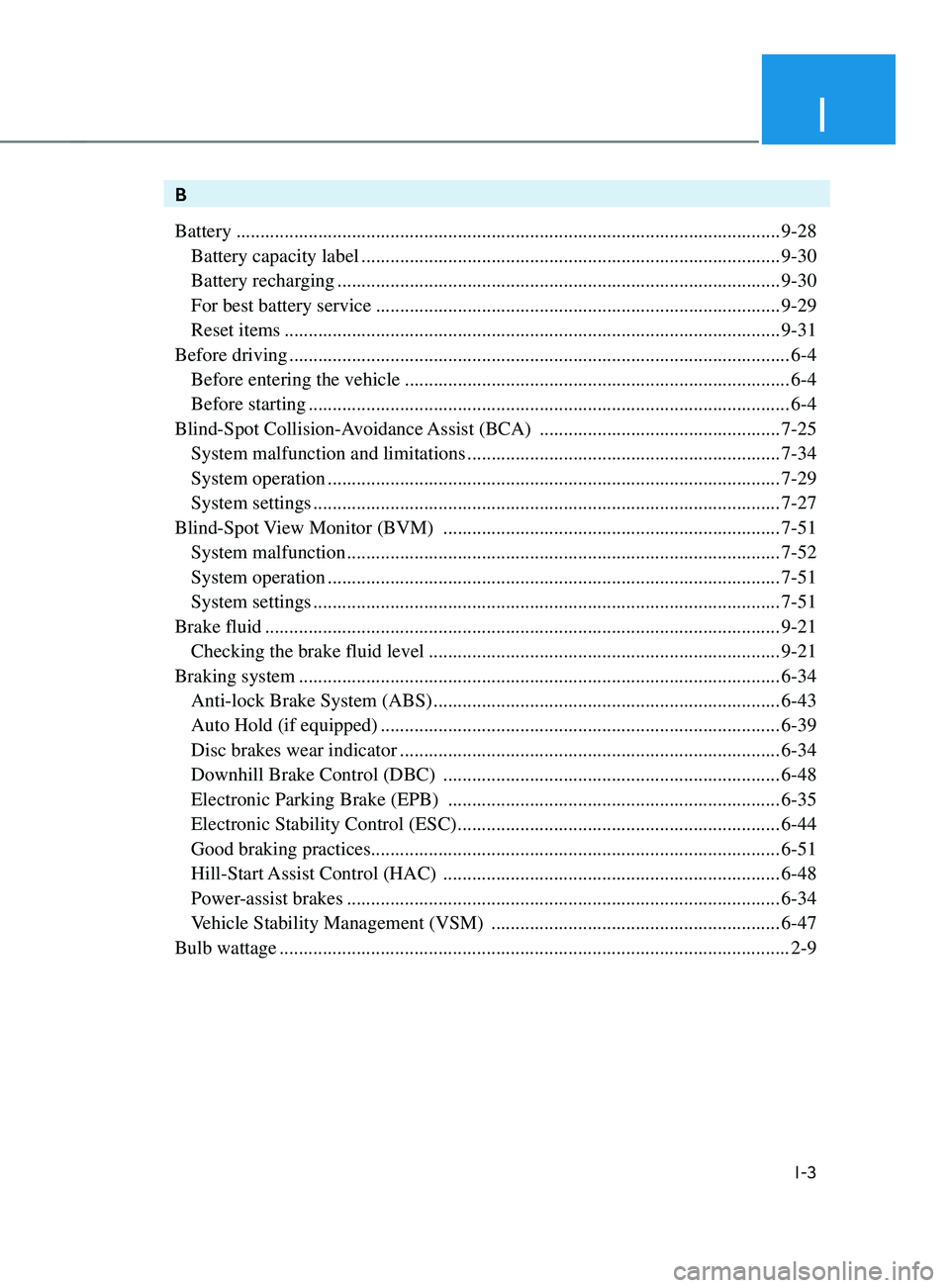
Battery
........................................................................\
.........................................9-28
Battery capacity label ........................................................................\
...............9-30
Battery recharging ........................................................................\
.................... 9-30
For best battery service ........................................................................\
............9-29
Reset items ........................................................................\
............................... 9-31
Before driving
........................................................................\
................................ 6-4
Before entering the vehicle ........................................................................\
........6-4
Before starting ........................................................................\
............................ 6-4
Blind-Spot Collision-Avoidance
Assist (BCA)
..................................................7-25
System malfunction and limitations ................................................................. 7-34
System operation ........................................................................\
...................... 7-29
System settings ........................................................................\
......................... 7-27
Blind-Spot
View Monitor (BVM)
...................................................................... 7-51
System malfunction ........................................................................\
.................. 7-52
System operation ........................................................................\
...................... 7-51
System settings ........................................................................\
......................... 7-51
Brake fluid
........................................................................\
................................... 9-21
Checking the brake fluid level ........................................................................\
.9-21
Braking system
........................................................................\
............................ 6-34
Anti-lock Brake System (ABS) ........................................................................\
6-43
Auto Hold (if equipped) ........................................................................\
........... 6-39
Disc brakes wear indicator ........................................................................\
.......6-34
Downhill Brake Control (DBC) ......................................................................6-48
Electronic Parking Brake (EPB) .....................................................................6-35
Electronic Stability Control (ESC) ...................................................................6-44
Good braking practices ........................................................................\
............. 6-51
Hill-Start Assist Control (HAC) ......................................................................6-48
Power-assist brakes ........................................................................\
.................. 6-34
Vehicle Stability Management (VSM) ............................................................6-47
Bulb wattage
........................................................................\
.................................. 2-9