2021 HYUNDAI SANTA FE CALLIGRAPHY instrument panel
[x] Cancel search: instrument panelPage 87 of 636
03
3-55
Main components of the Occupant
Classification System
• A detection device located within the
front passenger seat cushion.
• Electronic system to determine
whether the passenger air bag
systems should be activated or
deactivated.
• An indicator light located on the
instrument panel which illuminates
the words “PASSENGER AIR BAG OFF”
indicating the front passenger air bag
system is deactivated.
• The instrument panel air bag indicator
light is interconnected with the OCS.
The OCS is designed to help detect
the presence of a properly-seated
front passenger and determine if the
passenger’s front air bag should be
enabled (may inflate) or not.
The purpose is to help reduce the risk
of injury or death from an inflating air
bag to certain front passenger seat
occupants, such as children, by requiring
the air bag to be automatically turned
OFF.
For example, if a child restraint of the
type specified in the regulations is on the
seat, the occupant classification sensor
can detect it and cause the air bag to
turn OFF.
Front passenger seat adult occupants
who are properly seated and wearing the
seat belt properly, should not cause the
passenger air bag to be automatically
turned OFF. For smaller adults it may turn
OFF, however, if the occupant does not
sit in the seat properly (for example, by
not sitting upright, by sitting on the edge
of the seat, or by otherwise being out of
position), this could cause the sensor to
turn the air bag OFF. You will find the “PASSENGER AIR BAG
OFF” indicator on the overhead console
panel. This system detects the conditions
1-4 in the following table and activates or
deactivates the front passenger air bag
based on these conditions.
Always be sure that you and all vehicle
occupants are seated properly and
wearing the seat belt properly for the
most effective protection by the air bag
and the seat belt.
The OCS may not function properly if the
passenger takes actions which can affect
the classification system. These include:
•
Failing to sit in an upright position.
• Leaning against the door or center
console.
• Sitting towards the sides of the front
of the seat.
• Putting their legs on the dashboard or
resting them on other locations which
reduce the passenger weight on the
front seat.
• Wearing the seat belt improperly.
• Reclining the seatback.
• Wearing thick clothes like ski wear or
hip protection wear.
• Putting an additional thick cushion on
the seat.
• Putting electrical devices (e.g.
notebook, satellite radio) on the seat
with inverter charging.
Page 97 of 636
03
3-65
SRS care
The SRS is virtually maintenance-free
and there are no parts you can safely
service by yourself. If the SRS air bag
warning light does not illuminate when
the Engine Start/Stop button is in the
ON position, or continuously remains
on, we recommend that the system be
immediately inspected by an authorized
HYUNDAI dealer.
We recommend any work on the SRS
system, such as removing, installing,
repairing, or any work on the steering
wheel, the front passenger’s panel, front
seats and roof rails be performed by an
authorized HYUNDAI dealer. Improper
handling of the SRS system may result in
serious personal injury. WARNING
To reduce the risk of serious injury or
death take the following precautions:
• Do not attempt to modify or
disconnect the SRS components or
wiring, including the addition of any
kind of badges to the pad covers or
modifications to the body structure.
• Do not place objects over or near
the air bag modules on the steering
wheel, instrument panel, and the
front passenger’s panel above the
glove box.
• Clean the air bag pad covers with
a soft cloth moistened with plain
water. Solvents or cleaners could
adversely affect the air bag covers
and proper deployment of the
system.
• We recommend that inflated air
bags be replaced by an authorized
HYUNDAI dealer.
• If components of the air bag system
must be discarded, or if the vehicle
must be scrapped, certain safety
precautions must be observed.
We recommend that you consult
an authorized HYUNDAI dealer for
the necessary information. Failure
to follow these precautions could
increase the risk of personal injury.
Page 99 of 636

Instrument cluster
Instrument cluster ........................................................................\
....................4-4Instrument cluster control ........................................................................\
...................4-5
Instrumen t panel illumination ........................................................................\
........... 4-5
Gauges and me
ters
........................................................................\
.............................. 4-5
Speedome
ter
........................................................................\
..................................... 4-5
T
achometer
........................................................................\
.....................................
...4-5
Engine coolant temperature gauge
........................................................................\
. 4-6
Fuel gauge ........................................................................\
.....................................
....4-6
Outside temperature gauge
........................................................................\
.............. 4
-7
Odometer
........................................................................\
.....................................
.....4-8
Distance to empty
........................................................................\
............................ 4-8
F
uel economy (for 12.3-inch cluster)
...................................................................... 4-9
T
ransmission shift indicator
........................................................................\
................ 4-9
A
utomatic transmission / Dual clutch transmission shift indicator
..................... 4-9
W
arning and indicator lights
........................................................................\
............. 4-
10
Seat belt warning light
........................................................................\
.................... 4-
10
Air bag warning light
........................................................................\
....................... 4-
10
Parking brake & Brake fluid warning light
.............................................................. 4-10
An
ti-lock Brake System (ABS) warning light
........................................................... 4-
11
Electronic Brake Force Distribution (EBD) system warning light
.......................... 4-
11
Electric Power Steering (EPS) warning light
.......................................................... 4-
12
Charging system warning light
........................................................................\
....... 4-
12
Engine oil pressure warning light
........................................................................\
... 4-
13
Low fuel level warning light
........................................................................\
............ 4-
13
Malfunction Indicator Lamp (MIL)
........................................................................\
.. 4-13
Exhaus
t system (GPF) warning light (for gasoline engine)
................................... 4-
14
Electronic Parking Brake (EPB) warning light
........................................................ 4-
14
AUTO HOLD indicator light
........................................................................\
............. 4-
15
Low tire pressure warning light
........................................................................\
...... 4-
15
Forward Safety warning light
........................................................................\
.......... 4-16
Lane Sa
fety indicator light
........................................................................\
.............. 4-
16
4 Wheel Drive (4WD) warning light
........................................................................\
4-
16
4 Wheel Drive (4WD) LOCK Indicator Light
............................................................ 4-17
LED headligh
t warning light
........................................................................\
............. 4-
17
Icy road warning light
........................................................................\
...................... 4-
18
Electronic Stability Control (ESC) indicator light
................................................... 4-
18
Electronic Stability Control (ESC) OFF indicator light
........................................... 4-
18
Immobilizer Indicator Light (without smart key)
.................................................. 4-
19
Immobilizer Indicator Light (with smart key)
......................................................... 4-
19
Downhill Brake Control (DBC) indicator light
........................................................
4-20
4. Instrument cluster
4
Page 103 of 636

04
4-5
Instrument cluster control
Instrument panel illumination
When the vehicle’s parking lights or
headlamps are on, press the illumination
control switch to adjust the brightness of
the instrument panel illumination.
When pressing the illumination control
switch, the interior switch illumination
intensity also adjusted.
You can adjust the brightness of the
instrument panel illumination form the
User Settings Mode on the LCD display
when
the ignition s
witch
is on (‘Ligh
ts
→ Illumination
’). When the vehicle’s parking
lights or headlamps are on, interior
switch illumination intensity and mood
lamps are also adjusted.
If your vehicle is equipped with
additional navigation, please refer
to the infotainment system manual
separately supplied.
WARNING
Never adjust the instrument cluster
while driving. This could result in loss
of control and lead to an accident that
may cause death, serious injury, or
vehicle damage.
• The brightness of the instrument
panel illumination is displayed.
• If the brightness reaches to the
maximum or minimum level, a chime
will sound.
Gauges and meters
Speedometer
„„4.2-inch „„12.3-inch
OTM040059LOTM040006L
The speedometer indicates the speed of
the vehicle and is calibrated in miles per
hour (MPH) and/or kilometers per hour
(km/h).
Tachometer
„„4.2-inch„„12.3-inch
OTM040007LOTM040008LThe tachometer indicates the
approximate number of engine
revolutions per minute (rpm).
Use the tachometer to select the correct
shift points and to prevent lugging and/
or over-revving the engine.
NOTICE
Do not operate the engine within the
tachometer's RED ZONE. This may
cause severe engine damage.
Page 183 of 636
05
5-39
OTM050087
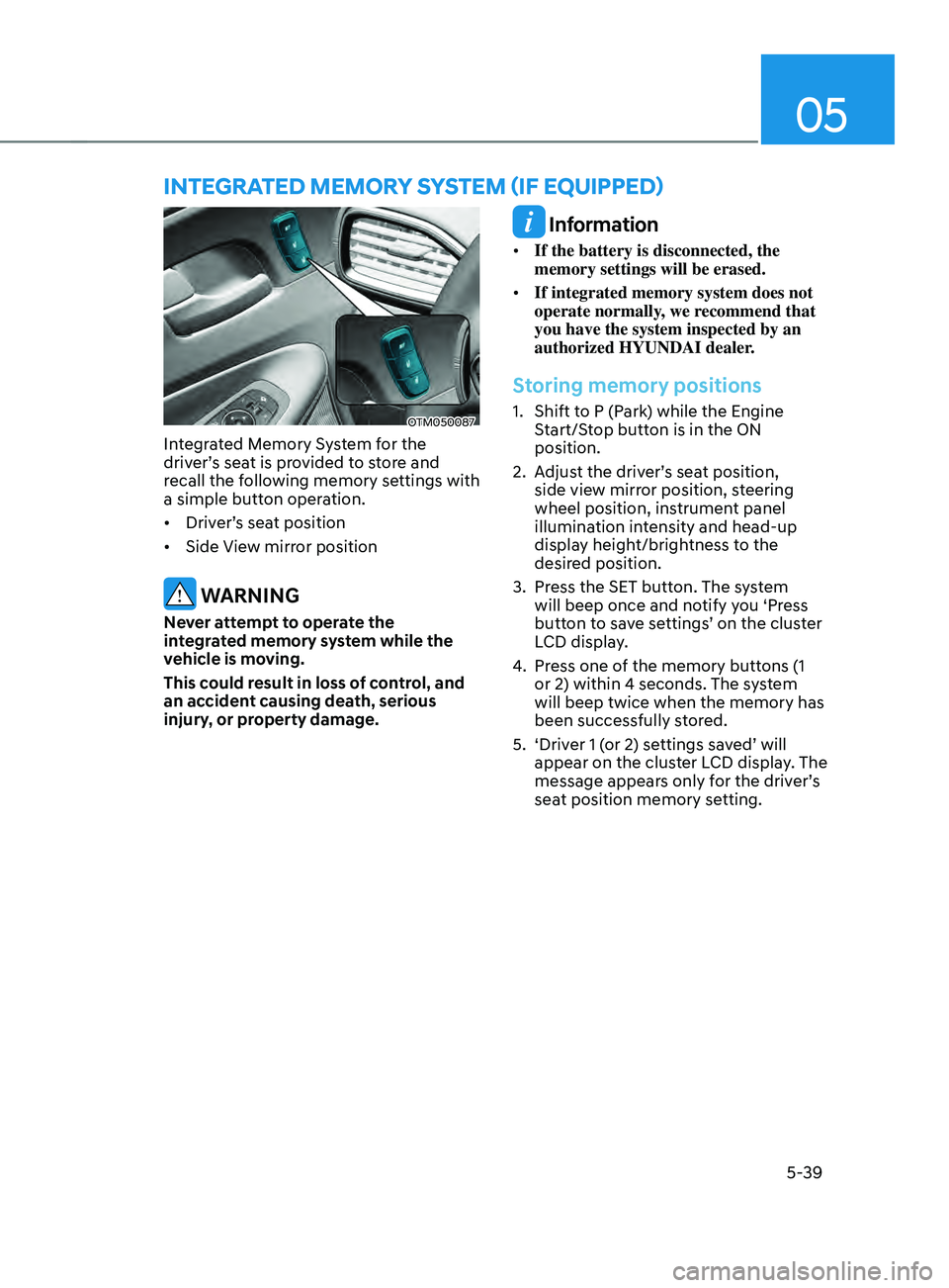
Integrated Memory System for the
driver’s seat is provided to store and
recall the following memory settings with
a simple button operation.
• Driver’s seat position
• Side View mirror position
WARNING
Never attempt to operate the
integrated memory system while the
vehicle is moving.
This could result in loss of control, and
an accident causing death, serious
injury, or property damage.
Information
• If the battery is disconnected, the
memory settings will be erased.
• If integrated memory system does not
operate normally, we recommend that
you have the system inspected by an
authorized HYUNDAI dealer.
Storing memory positions
1. Shift to P (Park) while the Engine
S
tart/Stop button is in the ON
position.
2.
Adjus
t the driver’s seat position,
side view mirror position, steering
wheel position, instrument panel
illumination intensity and head-up
display height/brightness to the
desired position.
3.
Press the SET butt
on. The system
will beep once and notify you ‘Press
button to save settings’ on the cluster
LCD display.
4.
Press one o
f the memory buttons (1
or 2) within 4 seconds. The system
will beep twice when the memory has
been successfully stored.
5.
‘Driver 1 (
or 2) settings saved’ will
appear on the cluster LCD display. The
message appears only for the driver’s
seat position memory setting.
InTEgRATED mEmOR Y sYsTEm (IF E QUIppED)
Page 184 of 636
Convenient features
5-40
Recalling memory positions
1. Shift to P (Park) while the Engine
Start/Stop button is in the ON
position.
2.
Press the desir
ed memory button (1
or 2). The system will beep once, and
then the driver’s seat position, side
view mirror position, steering wheel
position, instrument panel illumination
intensity and head-up display height/
brightness will automatically adjust to
the stored positions.
3.
‘Driver 1 (
or 2) settings applied’ will
appear on the cluster LCD display.
Information
• If you press the SET button or the
corresponding button which the
setting is being recalled, the setting will
temporarily deactivate. If you press the
other buttons, the setting of the pressed
button will activate.
For example, if you press the SET
button or number 1 button with the
number 1 setting in operation, the
setting will temporarily deactivate. If
you press the number 2 button, the
number 2 setting will activate.
• If you adjust the seat, rearview mirror,
steering wheel, instrument panel
illumination or head-up display while
recalling the stored positions, the pre-
set settings will become ineffective.
Resetting the system
Take the following procedures to reset
integrated memory system, when it does
not operate properly.
Resetting integrated memory
system
1. Stop the vehicle and open the driver’s
door with the E
ngine Start/Stop
button in the ON position and the
vehicle shifted to P (Park).
2.
Adjus
t the driver’s seat and seatback
to the foremost position.
3.
Press the SET butt
on and push
forward the driver’s seat movement
switch over 2 seconds simultaneously.
While resetting integrated memory
system
1. Resetting starts with a notification
sound.
2.
The driver’
s seat and seatback is
adjusted to the rearward position with
the notification sound.
3.
The driver’
s seat and seatback is
re-adjusted to the default position
(central position) with the notification
sound.
However, in the following cases, the
resetting procedure and the notification
sound may stop.
• The memory button is pressed.
• The seat control switch is operated.
• The gear is shifted out of P (Park).
• The driving speed exceeds
2 mph (3km/h).
• The driver’s door is closed.
Page 227 of 636
05
5-83
OIG046412
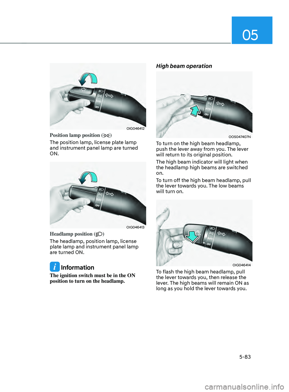
Position lamp position ()
The position lamp, license plate lamp
and instrument panel lamp are turned
ON.
OIG046413
Headlamp position ()
The headlamp, position lamp, license
plate lamp and instrument panel lamp
are turned ON.
Information
The ignition switch must be in the ON
position to turn on the headlamp.
High beam operation
OOS047407N
To turn on the high beam headlamp,
push the lever away from you. The lever
will return to its original position.
The high beam indicator will light when
the headlamp high beams are switched
on.
To turn off the high beam headlamp, pull
the lever towards you. The low beams
will turn on.
OIG046414
To flash the high beam headlamp, pull
the lever towards you, then release the
lever. The high beams will remain ON as
long as you hold the lever towards you.
Page 244 of 636
Convenient features5-100
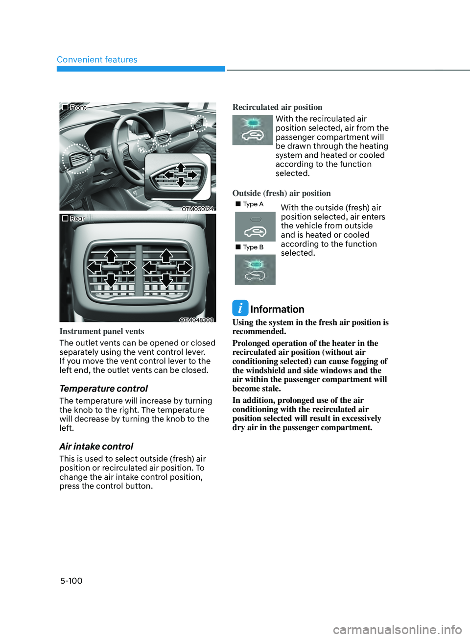
„„Front
OTM050124
„„Rear
OTM048308
Instrument panel vents
The outlet vents can be opened or closed
separately using the vent control lever.
If you move the vent control lever to the
left end, the outlet vents can be closed.
Temperature control
The temperature will increase by turning
the knob to the right. The temperature
will decrease by turning the knob to the
left.
Air intake control
This is used to select outside (fresh) air
position or recirculated air position. To
change the air intake control position,
press the control button. Recirculated air position
With the recirculated air
position selected, air from the
passenger compartment will
be drawn through the heating
system and heated or cooled
according to the function
selected.
Outside (fresh) air position
„„Type AWith the outside (fresh) air
position selected, air enters
the vehicle from outside
and is heated or cooled
according to the function
selected.
„„Type B
Information
Using the system in the fresh air position is
recommended.
Prolonged operation of the heater in the
recirculated air position (without air
conditioning selected) can cause fogging of
the windshield and side windows and the
air within the passenger compartment will
become stale.
In addition, prolonged use of the air
conditioning with the recirculated air
position selected will result in excessively
dry air in the passenger compartment.