2021 HYUNDAI IONIQ ELECTRIC coolant
[x] Cancel search: coolantPage 467 of 546
7-8
Maintenance
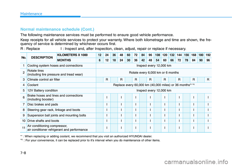
Normal maintenance schedule (Cont.)
The following maintenance services must be performed to ensure good vehicle performance.
Keep receipts for all vehicle services to protect your warranty. Where both kilometrage and time are shown, the fre-
quency of service is determined by whichever occurs first.
R : Replace I : Inspect and, after Inspection, clean, adjust, repair or replace if necessary.
No.DESCRIPTIONKILOMETERS X 10001224364860728496108120132144156168180192
MONTHS6121824303642485460667278849096
1Cooling system hoses and connectionsInspect every 12,000 km
2Rotate tires
(including tire pressure and tread wear)Rotate every 6,000 km or 6 months
3Climate control air filterRRRRRRRR
4CoolantReplace every 60,000 km (40,000 miles) or 36 months*1
*2
512V Battery conditionInspect every 12,000 km
6Brake hoses and lines and connections (including booster)IIIIIIII
7Disc brakes and padsIIIIIIII
8Steering gear rack, linkage and bootsIIIIIIII
9Suspension ball joints and mounting boltsIIIIIIII
10Drive shafts and bootsIIIIIIII
11Air conditioning compressor,
air conditioner refrigerant and performanceIIIIIIII
*
1
: When replacing or adding coolant, we recommend that you visit an authorized HYUNDAI dealer.
* 2
:For your convenience, it can be replaced prior to it's interval when you do maintenance of other items.
Page 470 of 546
7-11
7
Maintenance
EEXX PPLLAA NN AATTIIOO NN OO FF SS CC HH EEDD UU LLEE DD MM AAIINN TTEENN AANN CCEE IITT EEMM SS
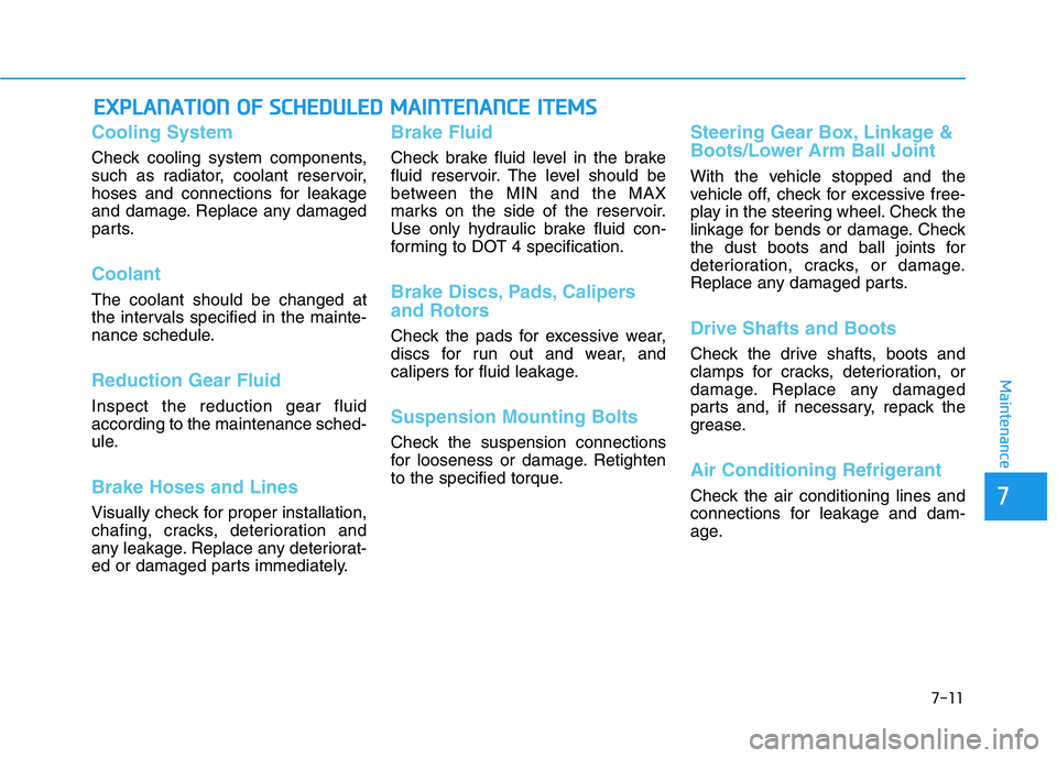
Cooling System
Check cooling system components,
such as radiator, coolant reservoir,
hoses and connections for leakage
and damage. Replace any damaged
parts.
Coolant
The coolant should be changed at
the intervals specified in the mainte-
nance schedule.
Reduction Gear Fluid
Inspect the reduction gear fluid according to the maintenance sched-
ule.
Brake Hoses and Lines
Visually check for proper installation,
chafing, cracks, deterioration and
any leakage. Replace any deteriorat-
ed or damaged parts immediately.
Brake Fluid
Check brake fluid level in the brake
fluid reservoir. The level should be
between the MIN and the MAX
marks on the side of the reservoir.
Use only hydraulic brake fluid con-
forming to DOT 4 specification.
Brake Discs, Pads, Calipers
and Rotors
Check the pads for excessive wear,
discs for run out and wear, and
calipers for fluid leakage.
Suspension Mounting Bolts
Check the suspension connections
for looseness or damage. Retighten
to the specified torque.
Steering Gear Box, Linkage &
Boots/Lower Arm Ball Joint
With the vehicle stopped and the
vehicle off, check for excessive free-
play in the steering wheel. Check the
linkage for bends or damage. Check
the dust boots and ball joints for
deterioration, cracks, or damage.
Replace any damaged parts.
Drive Shafts and Boots
Check the drive shafts, boots and
clamps for cracks, deterioration, or
damage. Replace any damaged
parts and, if necessary, repack the
grease.
Air Conditioning Refrigerant
Check the air conditioning lines and
connections for leakage and dam-
age.
Page 471 of 546
7-12
MaintenanceC
C OO OO LLAA NN TT
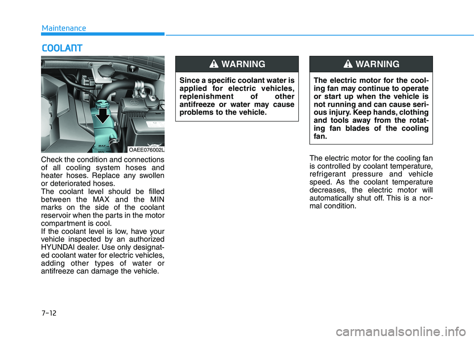
Check the condition and connections of all cooling system hoses and
heater hoses. Replace any swollen
or deteriorated hoses.
The coolant level should be filled
between the MAX and the MIN
marks on the side of the coolant
reservoir when the parts in the motor
compartment is cool.
If the coolant level is low, have your
vehicle inspected by an authorized
HYUNDAI dealer. Use only designat-
ed coolant water for electric vehicles,
adding other types of water or
antifreeze can damage the vehicle. The electric motor for the cooling fan
is controlled by coolant temperature,
refrigerant pressure and vehicle
speed. As the coolant temperature
decreases, the electric motor will
automatically shut off. This is a nor-mal condition.
OAEE076002L
Since a specific coolant water is
applied for electric vehicles,replenishment of other
antifreeze or water may cause
problems to the vehicle.
WARNING
The electric motor for the cool-
ing fan may continue to operate
or start up when the vehicle isnot running and can cause seri-
ous injury. Keep hands, clothing
and tools away from the rotat-
ing fan blades of the coolingfan.
WARNING
Page 473 of 546
7-14
MaintenanceW
W AASSHH EERR FF LLUU IIDD
Checking the Washer Fluid
Level
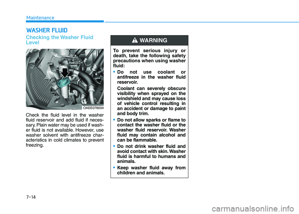
Check the fluid level in the washer
fluid reservoir and add fluid if neces-
sary. Plain water may be used if wash-
er fluid is not available. However, use
washer solvent with antifreeze char-
acteristics in cold climates to preventfreezing.
OAEE076004 To prevent serious injury or
death, take the following safetyprecautions when using washerfluid:
Do not use coolant or
antifreeze in the washer fluid
reservoir.
Coolant can severely obscure
visibility when sprayed on the
windshield and may cause loss
of vehicle control resulting in
an accident or damage to paint
and body trim.
Do not allow sparks or flame to contact the washer fluid or the
washer fluid reservoir. Washer
fluid may contain alcohol and
can be flammable.
Do not drink washer fluid and
avoid contact with skin. Washerfluid is harmful to humans andanimals.
Keep washer fluid away from
children and animals.
WARNING
Page 492 of 546
7-33
7
Maintenance
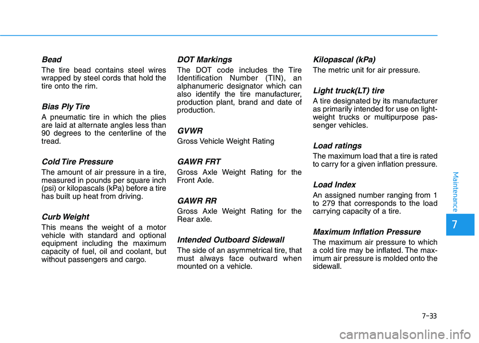
Bead
The tire bead contains steel wires
wrapped by steel cords that hold the
tire onto the rim.
Bias Ply Tire
A pneumatic tire in which the plies
are laid at alternate angles less than
90 degrees to the centerline of thetread.
Cold Tire Pressure
The amount of air pressure in a tire,measured in pounds per square inch
(psi) or kilopascals (kPa) before a tire
has built up heat from driving.
Curb Weight
This means the weight of a motor
vehicle with standard and optional
equipment including the maximum
capacity of fuel, oil and coolant, but
without passengers and cargo.
DOT Markings
The DOT code includes the TireIdentification Number (TIN), an
alphanumeric designator which can
also identify the tire manufacturer,
production plant, brand and date ofproduction.
GVWR
Gross Vehicle Weight Rating
GAWR FRT
Gross Axle Weight Rating for the
Front Axle.
GAWR RR
Gross Axle Weight Rating for the
Rear axle.
Intended Outboard Sidewall
The side of an asymmetrical tire, that
must always face outward when
mounted on a vehicle.
Kilopascal (kPa)
The metric unit for air pressure.
Light truck(LT) tire
A tire designated by its manufacturer
as primarily intended for use on light-
weight trucks or multipurpose pas-
senger vehicles.
Load ratings
The maximum load that a tire is rated
to carry for a given inflation pressure.
Load Index
An assigned number ranging from 1to 279 that corresponds to the load
carrying capacity of a tire.
Maximum Inflation Pressure
The maximum air pressure to which
a cold tire may be inflated. The max-
imum air pressure is molded onto the
sidewall.
Page 536 of 546
8-6
Specifications & Consumer informationR
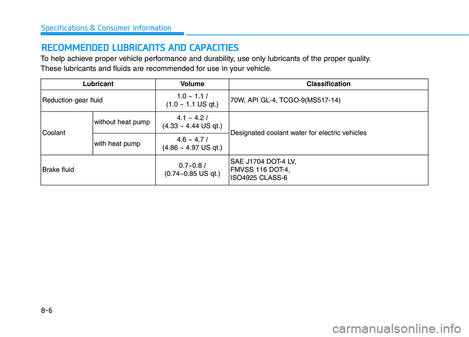
R EECCOO MM MMEENN DDEEDD LL UU BBRRIICC AA NN TTSS AA NN DD CC AA PPAA CCIITT IIEE SS
To help achieve proper vehicle performance and durability, use only lubricants of the proper quality.
These lubricants and fluids are recommended for use in your vehicle.
Lubricant Volume Classification
Reduction gear fluid 1.0 ~ 1.1
l
(1.0 ~ 1.1 US qt.) 70W, API GL-4, TCGO-9(MS517-14)
Coolant without heat pump
4.1 ~ 4.2
l
(4.33 ~ 4.44 US qt.) Designated coolant water for electric vehicles
with heat pump 4.6 ~ 4.7
l
(4.86 ~ 4.97 US qt.)
Brake fluid 0.7~0.8
l
(0.74~0.85 US qt.) SAE J1704 DOT-4 LV,
FMVSS 116 DOT-4,ISO4925 CLASS-6
Page 541 of 546
I-3
Child restraint system (CRS) ..........................................2-36
Children Always in the Rear ......................................2-36
Installing a Child Restraint System (CRS) ................2-39
Selecting a Child Restraint System (CRS).................2-37
Climate control additional features .............................3-125 Automatic Ventilation...............................................3-125
Climate control air filter .................................................7-15 Filter Inspection..........................................................7-15
Coolant ............................................................................7-12
Defroster .......................................................................3-108 Rear Window Defroster............................................3-108
Dimensions .......................................................................8-2
Door locks .........................................................................3-9 Auto Door Lock/Unlock Features ..............................3-12
Child-Protector Rear Door locks................................3-12
Operating Door Locks from Inside the Vehicle ........3-10
Operating Door Locks from Outside the Vehicle .......3-9
Drive Mode Integrated Control System ........................5-44
Drive mode .................................................................5-44
Initial setting for each Drive Mode ............................5-44
Driver Attention Warning (DAW) .................................5-83
Leading Vehicle Departure Alert ...............................5-89
Resetting the system ..................................................5-86 System malfunction ....................................................5-86
System setting and operation .....................................5-83
System standby...........................................................5-86
Driver position memory system .....................................3-14
Easy Access Function .................................................3-15
Recalling positions from memory ..............................3-15
Storing Positions into Memory .................................3-14
Electric vehicle specifications ..........................................8-2
Explanation of scheduled maintenance items .................7-11
Exterior features..............................................................3-39 Charging Door ............................................................3-43
Hood ...........................................................................3-39
Tailgate .......................................................................3-41
Exterior Overview.............................................................1-2
Forward Collision-Avoidance assist (FCA) ..................5-45 FCA sensor (Front view camera+ Front radar) ..........5-50
FCA warning message and brake control ..................5-47
Limitations of the system ...........................................5-54
System malfunction ....................................................5-52
System setting and activation .....................................5-45
Fuses ...............................................................................7-39 Fuse/Relay Panel Description ....................................7-43
Instrument Panel Fuse Replacement ........................7-40
Motor Compartment Panel Fuse Replacement ..........7-41
I
Index
C
D
E
F