2021 HYUNDAI I30 Symbol
[x] Cancel search: SymbolPage 5 of 659
We want to help you get the greatest
possible driving pleasure from your
vehicle. Your Owner’s Manual can
assist you in many ways. We strong-
ly recommend that you read the
entire manual. In order to minimize
the chance of death or injury, you
must read the WARNING and CAU-
TION sections in the manual.
Illustrations complement the words
in this manual to best explain how to
enjoy your vehicle. By reading your
manual, you will learn about fea-
tures, important safety information,
and driving tips under various road
conditions.
The general layout of the manual is
provided in the Table of Contents.
Use the index when looking for a
specific area or subject; it has an
alphabetical listing of all information
in your manual.
Sections: This manual has eight
chapters plus an index. Each chapter
begins with a brief list of contents so
you can tell at a glance if that section
has the information you want.Your safety, and the safety of others,
is very important. This Owner's
Manual provides you with many safe-
ty precautions and operating proce-
dures. This information alerts you to
potential hazards that may hurt you
or others, as well as damage to your
vehicle.
Safety messages found on vehicle
labels and in this manual describe
these hazards and what to do to
avoid or reduce the risks.
Warnings and instructions contained
in this manual are for your safety.
Failure to follow safety warnings and
instructions can lead to serious injury
or death.
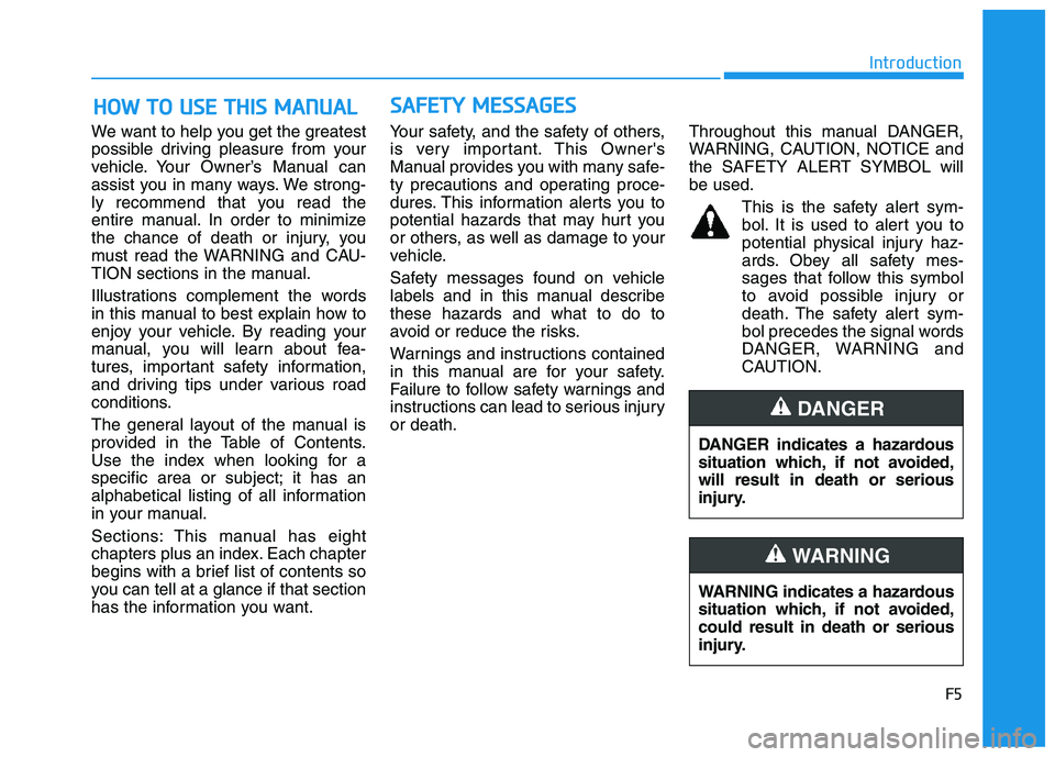
Throughout this manual DANGER,
WARNING, CAUTION, NOTICE and
the SAFETY ALERT SYMBOL will
be used.
This is the safety alert sym-bol. It is used to alert you to
potential physical injury haz-
ards. Obey all safety mes-
sages that follow this symbol
to avoid possible injury or
death. The safety alert sym-
bol precedes the signal words
DANGER, WARNING and
CAUTION.
H
H O
O W
W
T
T O
O
U
U S
S E
E
T
T H
H I
I S
S
M
M A
A N
N U
U A
A L
L S
S A
A F
F E
E T
T Y
Y
M
M E
E S
S S
S A
A G
G E
E S
S
F5
Introduction
DANGER indicates a hazardous
situation which, if not avoided,
will result in death or serious
injury.
DANGER
WARNING indicates a hazardous
situation which, if not avoided,
could result in death or serious
injury.
WARNING
Page 59 of 659
2-39
Safety system of your vehicle
2
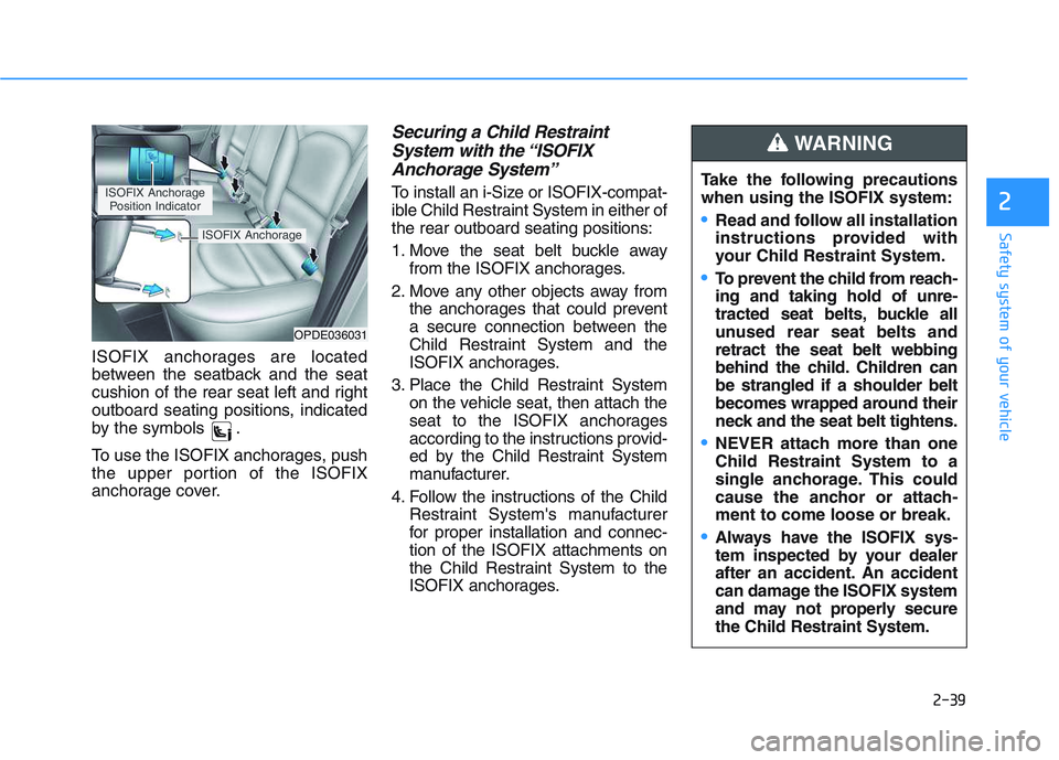
ISOFIX anchorages are located
between the seatback and the seat
cushion of the rear seat left and right
outboard seating positions, indicated
by the symbols .
To use the ISOFIX anchorages, push
the upper portion of the ISOFIX
anchorage cover.
Securing a Child Restraint System with the “ISOFIXAnchorage System”
To install an i-Size or ISOFIX-compat-
ible Child Restraint System in either of
the rear outboard seating positions:
1. Move the seat belt buckle away
from the ISOFIX anchorages.
2. Move any other objects away from the anchorages that could prevent
a secure connection between the
Child Restraint System and the
ISOFIX anchorages.
3. Place the Child Restraint System on the vehicle seat, then attach the
seat to the ISOFIX anchorages
according to the instructions provid-
ed by the Child Restraint System
manufacturer.
4. Follow the instructions of the Child Restraint System's manufacturer
for proper installation and connec-
tion of the ISOFIX attachments on
the Child Restraint System to the
ISOFIX anchorages.
OPDE036031
ISOFIX Anchorage
Position Indicator
ISOFIX Anchorage
Take the following precautions
when using the ISOFIX system:
Read and follow all installation
instructions provided with
your Child Restraint System.
To prevent the child from reach-
ing and taking hold of unre-
tracted seat belts, buckle all
unused rear seat belts and
retract the seat belt webbing
behind the child. Children can
be strangled if a shoulder belt
becomes wrapped around their
neck and the seat belt tightens.
NEVER attach more than one
Child Restraint System to a
single anchorage. This could
cause the anchor or attach-
ment to come loose or break.
Always have the ISOFIX sys-
tem inspected by your dealer
after an accident. An accident
can damage the ISOFIX system
and may not properly secure
the Child Restraint System.
WARNING
Page 73 of 659

2-53
Safety system of your vehicle
2
SRS warning light
The SRS (Supplement Restraint
System) air bag warning light on the
instrument panel displays the air bag
symbol depicted in the illustration. The
system checks the air bag electrical
system for malfunctions. The light indi-
cates that there is a potential problem
with your air bag system, which could
include your side and/or curtain air
bags used for rollover protection (if
equipped with rollover sensor).During a moderate to severe frontal
collision, sensors will detect the vehi-
cle’s rapid deceleration. If the rate of
deceleration is high enough, the con-
trol unit will inflate the front air bags,
at the time and with the force needed.
The front air bags help protect the driv-
er and front passenger by responding
to frontal impacts in which seat belts
alone cannot provide adequate
restraint. When needed, the side air
bags help provide protection in the
event of a side impact or rollover by
supporting the side upper body area.
Air bags are activated (able to inflate
if necessary) only when the ignition
switch is in the ON position.
Air bags inflate in the event of certain frontal or side collisions to help pro-
tect the occupants from serious
physical injury.
There is no single speed at which the air bags will inflate. Generally, air bags
are designed to inflate based upon
the severity of a collision and its direc-
tion. These two factors determine
whether the sensors produce an elec-
tronic deployment/inflation signal.
If your SRS malfunctions, the
air bag may not inflate properly
during an accident increasing
the risk of serious injury or
death.
If any of the following condi-
tions occur, your SRS is mal-
functioning:
The light does not turn on for
approximately six seconds
when the ignition switch is in
the ON position.
The light stays on after illumi-
nating for approximately six
seconds.
The light comes on while the
vehicle is in motion.
The light blinks when the
engine is running.
We recommend that an author-
ized HYUNDAI dealer inspect the
SRS as soon as possible if any
of these conditions occur.
WARNING
Page 122 of 659
3-120
Convenient features of your vehicle
Air conditioning refrigerantlabel
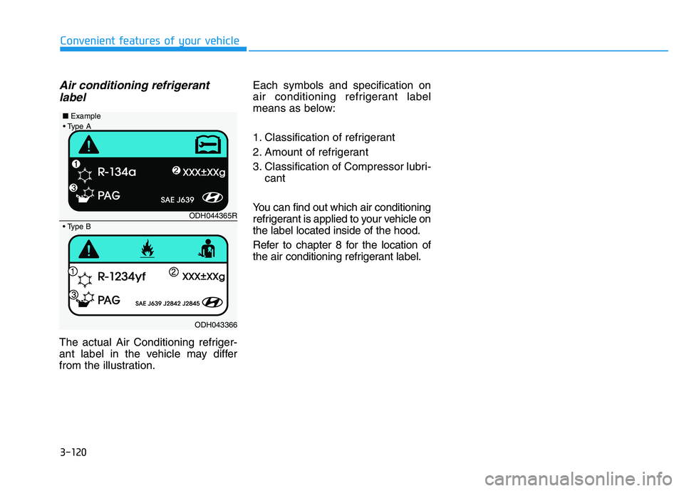
The actual Air Conditioning refriger-
ant label in the vehicle may differ
from the illustration. Each symbols and specification on
air conditioning refrigerant label
means as below:
1. Classification of refrigerant
2. Amount of refrigerant
3. Classification of Compressor lubri-
cant
You can find out which air conditioning
refrigerant is applied to your vehicle on
the label located inside of the hood.
Refer to chapter 8 for the location of
the air conditioning refrigerant label.
ODH044365R
ODH043366
■
Example
Page 134 of 659
3-132
Convenient features of your vehicle
Air Conditioning refrigerantlabel
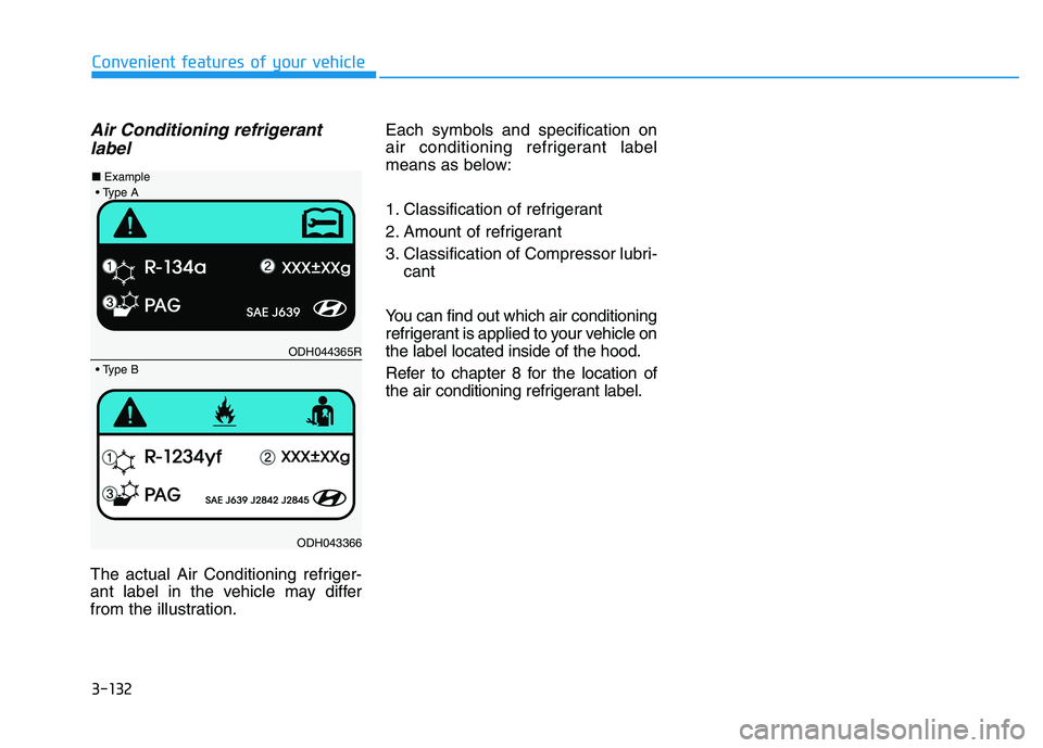
The actual Air Conditioning refriger-
ant label in the vehicle may differ
from the illustration. Each symbols and specification on
air conditioning refrigerant label
means as below:
1. Classification of refrigerant
2. Amount of refrigerant
3. Classification of Compressor lubri-
cant
You can find out which air conditioning
refrigerant is applied to your vehicle on
the label located inside of the hood.
Refer to chapter 8 for the location of
the air conditioning refrigerant label.
ODH044365R
ODH043366
■
Example
Page 138 of 659

3-136
Convenient features of your vehicle
Auto defogging system
(only for automatic climate
control system, if equipped)
Auto defogging reduces the possibil-
ity of fogging up the inside of the
windshield by automatically sensing
the moisture of inside the windshield.
The auto defogging system operates
when the heater or air conditioning is
on.
Information
The auto defogging system may not
operate normally, when the outside
temperature is below -10 °C.When the Auto Defogging
System operates, the indi-
cator will illuminate.
If higher level of moisture are sensed
in the vehicle, the Auto Defogging
System will operate in the following
order:
Step 1 : Outside air position
Step 2 : Operating the air conditioning
Step 3 : Blowing air toward the wind- shield
Step 4 : Increasing air flow toward the windshield
If the air conditioning is off or recircu-
lated air position is manually selected
while Auto Defogging System is ON,
the Auto Defogging System Indicator
will blink 3 times to signal that the
manual operation has been canceled.
To cancel or reset the Auto Defogging
System
Press the front windshield defroster
button for 3 seconds when the igni-
tion switch is in the ON position.
When the Auto Defogging System is
canceled, ADS OFF symbol will blink
3 times and the ADS OFF will be dis-
played on the climate control infor-
mation screen.
When the Auto Defogging System is
reset, ADS OFF symbol will blink 6
times without a signal.
Information
• When the air conditioning is turned on by Auto defogging system, if you
try to turn off the air conditioning, the
indicator will blink 3 times and the air
conditioning will not turn off.
• For efficiency, do not select recircu- lated air position while Auto defog-
ging system is operating.
Do not remove the sensor cover
located on the upper end of the
windshield glass.
Damage to system parts could
occur and may not be covered by
your vehicle warranty.
NOTICE
i
i
Page 171 of 659
3-21
Convenient features of your vehicle
3
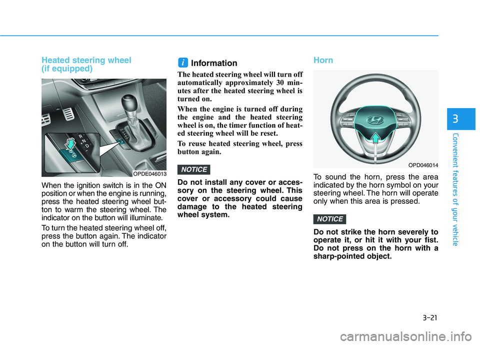
Heated steering wheel
(if equipped)
When the ignition switch is in the ON
position or when the engine is running,
press the heated steering wheel but-
ton to warm the steering wheel. The
indicator on the button will illuminate.
To turn the heated steering wheel off,
press the button again. The indicator
on the button will turn off.
Information
The heated steering wheel will turn off
automatically approximately 30 min-
utes after the heated steering wheel is
turned on.
When the engine is turned off during
the engine and the heated steering
wheel is on, the timer function of heat-
ed steering wheel will be reset.
To reuse heated steering wheel, press
button again.
Do not install any cover or acces-
sory on the steering wheel. This
cover or accessory could cause
damage to the heated steering
wheel system.
Horn
To sound the horn, press the area
indicated by the horn symbol on your
steering wheel. The horn will operate
only when this area is pressed.
Do not strike the horn severely to
operate it, or hit it with your fist.
Do not press on the horn with a
sharp-pointed object.
NOTICE
NOTICE
i
OPD046014
OPDE046013
Page 222 of 659

3-72
Convenient features of your vehicle
LCD modes
Modes SymbolExplanation
Trip Computer This mode displays driving information such as the tripmeter, fuel economy, etc.
For more details, refer to "Trip Computer" in this chapter.
Turn By Turn (TBT)This mode displays the state of the navigation.
Assist
• This mode displays the state of the Smart Cruise Control (SCC) and LaneDeparture Warning System (LDWS)/Lane Keeping Assist System (LKAS).
For more information, refer to "Smart Cruise Control (SCC)" and "Lane
Departure Warning System (LDWS)/Lane Keeping Assist System (LKAS)" in
chapter 5.
For more information, refer to "Driver Attention Alert (DAA)"in chapter 5 and
"Tire Pressure Monitoring System (TPMS)"in chapter 6.
User SettingsIn this mode, you can change settings of the doors, lamps, etc.
WarningThis mode displays warning messages related to the Blind Spot Detection system,
etc.
The information provided differs according to the items applied to your vehicle.