Page 491 of 555
Maintenance
9-22
Checking the Hybrid Starter &
Generator (HSG) Belt
Have the Hybrid Starter & Generator
(HSG) belt inspected or replaced
according to the Maintenance Schedule
in this chapter by an authorized
HYUNDAI dealer.
CAUTION
When the HSG belt is worn out or
damaged, replace the belt.
Otherwise, it may cause engine
overheating or battery discharge.
WARNING
• Turn the vehicle off while you inspect
the engine or Hybrid Starter &
Generator (HSG) belt. Otherwise it
may result in serious injury.
• Keep hands, clothing etc. away from
the Hybrid Starter & Generator (HSG)
belt.
HYBRID STARTER & GENERATOR (HSG) BELT
Page 508 of 555
09
9-39
Ply
A layer of rubber-coated parallel cords.
Pneumatic tire
A mechanical device made of rubber,
chemicals, fabric and steel or other
materials, that, when mounted on an
automotive wheel provides the traction
and contains the gas or fluid that
sustains the load.
Pneumatic options weight
The combined weight of installed regular
production options weighing over 5 lb.
(2.3 kg) in excess of the standard items
which they replace, not previously
considered in curb weight or accessory
weight, including heavy duty breaks, ride
levelers, roof rack, heavy duty battery,
and special trim.
Recommended Inflation Pressure
Vehicle manufacturer’s recommended
tire inflation pressure as shown on the
tire placard.
Radial Ply Tire
A pneumatic tire in which the ply cords
that extend to the beads are laid at 90
degrees to the centerline of the tread.
Rim
A metal support for a tire and upon
which the tire beads are seated.
Sidewall
The portion of a tire between the tread
and the bead.
Speed Rating
An alphanumeric code assigned to a tire
indicating the maximum speed at which
a tire can operate.
Traction
The friction between the tire and
the road surface. The amount of grip
provided.
Tread
The portion of a tire that comes into
contact with the road.
Treadwear Indicators
Narrow bands, sometimes called “wear
bars”, that show across the tread of a tire
when only 1/16 inch of tread remains.
UTQGS
Uniform Tire Quality Grading Standards
is a tire information system that provides
consumers with ratings for a tire’s
traction, temperature and treadwear.
Ratings are determined by tire
manufacturers using government testing
procedures. The ratings are molded into
the sidewall of the tire.
Vehicle Capacity Weight
The number of designated seating
positions multiplied by 150 lbs. (68 kg)
plus the rated cargo and luggage load.
Vehicle Maximum Load on the Tire
Load on an individual tire due to curb
and accessory weight plus maximum
occupant and cargo weight.
Vehicle Normal Load on the Tire
Load on an individual tire that is
determined by distributing to each axle
its share of the curb weight, accessory
weight, and normal occupant weight and
dividing by 2.
Vehicle Placard
A label permanently attached to a vehicle
showing the original equipment tire size
and recommended inflation pressure.
Page 511 of 555
Maintenance
9-42
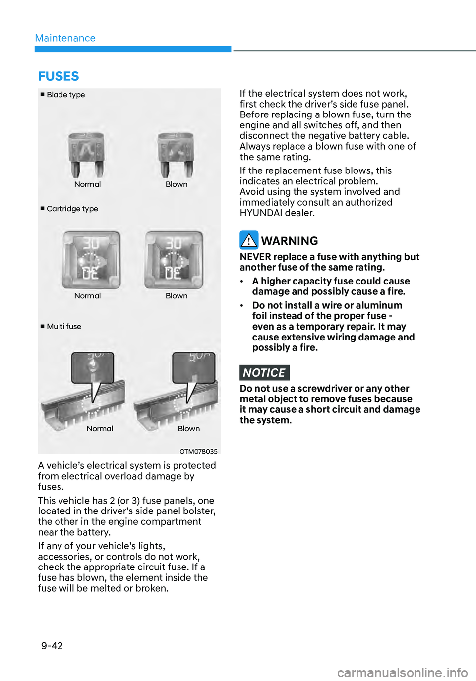
■ Cartridge type
■ Blade type
■ Multi fuse Normal
Blown
Normal Blown
Normal Blown
OTM078035
A vehicle’s electrical system is protected
from electrical overload damage by
fuses.
This vehicle has 2 (or 3) fuse panels, one
located in the driver’s side panel bolster,
the other in the engine compartment
near the battery.
If any of your vehicle’s lights,
accessories, or controls do not work,
check the appropriate circuit fuse. If a
fuse has blown, the element inside the
fuse will be melted or broken.
If the electrical system does not work,
first check the driver’s side fuse panel.
Before replacing a blown fuse, turn the
engine and all switches off, and then
disconnect the negative battery cable.
Always replace a blown fuse with one of
the same rating.
If the replacement fuse blows, this
indicates an electrical problem.
Avoid using the system involved and
immediately consult an authorized
HYUNDAI dealer.
WARNING
NEVER replace a fuse with anything but
another fuse of the same rating.
• A higher capacity fuse could cause
damage and possibly cause a fire.
• Do not install a wire or aluminum
foil instead of the proper fuse -
even as a temporary repair. It may
cause extensive wiring damage and
possibly a fire.
NOTICE
Do not use a screwdriver or any other
metal object to remove fuses because
it may cause a short circuit and damage
the system.
FUSES
Page 513 of 555
Maintenance
9-44
Engine Compartment Panel Fuse
Replacement
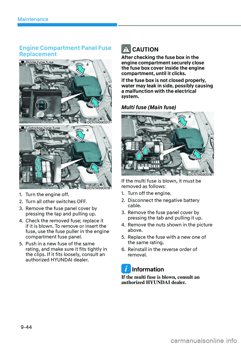
„„Blade type fuse
OCN7H090017
„„Cartridge type fuse
OCN7H090018
1. Turn the engine off.
2. Turn all other switches OFF.
3. Remove the fuse panel cover by
pressing the tap and pulling up.
4. Check the removed fuse; replace it
if it is blown. To remove or insert the
fuse, use the fuse puller in the engine
compartment fuse panel.
5. Push in a new fuse of the same
rating, and make sure it fits tightly in
the clips. If it fits loosely, consult an
authorized HYUNDAI dealer.
CAUTION
After checking the fuse box in the
engine compartment securely close
the fuse box cover inside the engine
compartment, until it clicks.
If the fuse box is not closed properly,
water may leak in side, possibly causing
a malfunction with the electrical
system.
Multi fuse (Main fuse)
OCN7H090016
If the multi fuse is blown, it must be
removed as follows:
1. Turn off the engine.
2. Disconnect the negative battery
cable.
3. Remove the fuse panel cover by
pressing the tab and pulling it up.
4. Remove the nuts shown in the picture
above.
5. Replace the fuse with a new one of
the same rating.
6. Reinstall in the reverse order of
removal.
Information
If the multi fuse is blown, consult an
authorized HYUNDAI dealer.
Page 515 of 555

Maintenance
9-46
Driver’s side fuse panel
Fuse NameFuse Rating
Circuit Protected
MEMORY1 10AA/C Controller, Instrument Cluster,
A/C Control Module, Driver IMS Control Module
AIR BAG2 10A
SRS Control Module
MODULE4 10AIBU, ATM Shift Lever Indicator, Front Console Switch,
ADAS Unit, Crash Pad Switch, LKA Unit, VESS Unit
MODULE7 7.5AIAU, ADAS Unit, Rear Seat Wamer Control Module,
Cooling Fan Motor
START 7.5ABurglar Alarm Relay, Transaxle Range Switch, IBU,
Ignition Switch
BATTERY
MANAGEMENT 10A
BMS Control Module
CLUSTER 7.5A
Instrument Cluster (IG1)
IBU2 7.5A
IBU
A/C1 7.5AA/C Controller, A/C Control Module, PM Sensor,
E/R Junction Block (Blower Relay, PTC Heater1/2 Relay),
Electronic A/C Compressor
TRUNK 10A
Trunk Relay
S/HEATER FRT 20AFront Ventilation Seat Control Module,
Front Seat Warmer Control Module
P/WINDOW LH 25A
Power Window Main Switch
MULTIMEDIA 15A
Audio, A/V & Navigation Head Unit
SPARE 1 (B+) 10A
Not Used (Black Box)
FCA 10A
Front Radar
MDPS 7.5A
MDPS Unit
MODULE6 7.5A
IBU
S/HEATER RR 20A
Rear Seat Warmer Control Module
SAFETY P/
WINDOW DRV 25A
Driver Safety Power Window Module
P/WINDOW RH 25APassenger Power Window Switch,
Power Window Main Switch
BRAKE SWITCH 10A
IBU, Stop Lamp Switch
IBU1 15A
IBU
Page 519 of 555
Maintenance
9-50
Engine compartment fuse panel
TypeFuse Name Fuse Rating
Circuit Protected
FUSE BATTERY C/
FAN 1 15A
Battery C/Fan Relay
IEB1 40A
IDB Unit, Multipurpose Check Connector
CLUTCH
ACTUATOR 30A
Clutch Actuator
POWER
OUTLET 1 40A
Power Outlet Relay
EWP 2 10A
Auxiliary Electric Water Pump
EWP 1 10A
Electric Water Pump
POWER
OUTLET 2 20A
Front Power Outlet
DCT 1 40A
TCM
DCT 2 40A
TCM
REAR
HEATED 40A
Rear Heated Relay
B+4 40AICU Junction Block (Power Window Relay,
Fuse - AIR BAG 2, IBU 1, BRAKE SWITCH,
DOOR LOCK, MODULE 1, SUNROOF, IAU,
BMS)
HEV ECU 1 10A
HPCU
IG3 20A
IG3 Relay
TCU 1 10A
TCM
FUEL PUMP 20A
Fuel Pump Relay
HEV ECU 2 10A
HPCU, BMS Control Module
Sub Block FUSE BATTERY C/
FAN 2 10A
Battery C/Fan Relay
Page 523 of 555
Maintenance
9-54
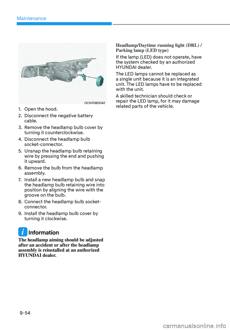
OCN7080042
1. Open the hood.
2. Disconnect the negative battery
cable.
3. Remove the headlamp bulb cover by
turning it counterclockwise.
4. Disconnect the headlamp bulb
socket-connector.
5. Unsnap the headlamp bulb retaining
wire by pressing the end and pushing
it upward.
6. Remove the bulb from the headlamp
assembly.
7. Install a new headlamp bulb and snap
the headlamp bulb retaining wire into
position by aligning the wire with the
groove on the bulb.
8. Connect the headlamp bulb socket-
connector.
9. Install the headlamp bulb cover by
turning it clockwise.
Information
The headlamp aiming should be adjusted
after an accident or after the headlamp
assembly is reinstalled at an authorized
HYUNDAI dealer.Headlamp/Daytime running light (DRL) /
Parking lamp (LED type)
If the lamp (LED) does not operate, have
the system checked by an authorized
HYUNDAI dealer.
The LED lamps cannot be replaced as
a single unit because it is an integrated
unit. The LED lamps have to be replaced
with the unit.
A skilled technician should check or
repair the LED lamp, for it may damage
related parts of the vehicle.
Page 524 of 555
09
9-55
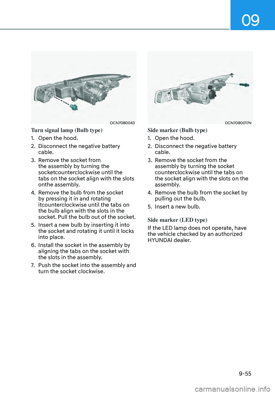
OCN7080043
Turn signal lamp (Bulb type)
1. Open the hood.
2. Disconnect the negative battery
cable.
3. Remove the socket from
the assembly by turning the
socketcounterclockwise until the
tabs on the socket align with the slots
onthe assembly.
4. Remove the bulb from the socket
by pressing it in and rotating
itcounterclockwise until the tabs on
the bulb align with the slots in the
socket. Pull the bulb out of the socket.
5. Insert a new bulb by inserting it into
the socket and rotating it until it locks
into place.
6. Install the socket in the assembly by
aligning the tabs on the socket with
the slots in the assembly.
7. Push the socket into the assembly and
turn the socket clockwise.
OCN7090017N
Side marker (Bulb type)
1. Open the hood.
2. Disconnect the negative battery
cable.
3. Remove the socket from the
assembly by turning the socket
counterclockwise until the tabs on
the socket align with the slots on the
assembly.
4. Remove the bulb from the socket by
pulling out the bulb.
5. Insert a new bulb.
Side marker (LED type)
If the LED lamp does not operate, have
the vehicle checked by an authorized
HYUNDAI dealer.