2021 HYUNDAI ELANTRA HYBRID coolant
[x] Cancel search: coolantPage 484 of 555
09
9-15
Engine Coolant/Inverter Coolant
The coolant should be changed at the
intervals specified in the maintenance
schedule.
Dual clutch transmission fluid
Dual clutch transmission fluid should
not be checked under normal usage
conditions.
We recommend that the Intelligent
variable transmission fluid is changed by
an authorized HYUNDAI dealer according
to the maintenance schedule.
Brake Hoses and Lines
Visually check for proper installation,
chafing, cracks, deterioration and any
leakage. Replace any deteriorated or
damaged parts immediately.
Brake Fluid
Check the brake fluid level in the brake
fluid reservoir. The level should be
between the MIN and the MAX marks
on the side of the reservoir. Use only
hydraulic brake fluid conforming to DOT
4 specification..
Brake Discs, Pads, Calipers and
Rotors
Check the pads for excessive wear, discs
for run out and wear, and calipers for
fluid leakage.
Suspension Mounting Bolts
Check the suspension connections for
looseness or damage. Retighten to the
specified torque.
Steering Gear Box, Linkage &
Boots/Lower Arm Ball Joint
With the vehicle stopped and the engine
off, check for excessive freeplay in the
steering wheel. Check the linkage for
bends or damage. Check the dust boots
and ball joints for deterioration, cracks,
or damage.
Replace any damaged parts.
Drive Shafts and Boots
Check the drive shafts, boots and clamps
for cracks, deterioration, or damage.
Replace any damaged parts and, if
necessary, repack the grease.
Air Conditioning Refrigerant
Check the air conditioning lines and
connections for leakage and damage.
Page 487 of 555
Maintenance
9-18
The high-pressure cooling system has a
reservoir filled with year-round antifreeze
coolant. The reservoir is filled at the
factory.
Check the antifreeze protection and
coolant level at least once a year, at
the beginning of the winter season and
before traveling to a colder climate.
NOTICE
• When the engine overheats by low
level of the engine coolant, suddenly
adding engine coolant may cause
cracks in the engine. To prevent
damage, add engine coolant slowly
in small quantities.
• Do not drive with no engine coolant.
It may cause water pump failure and
engine seizure, etc.
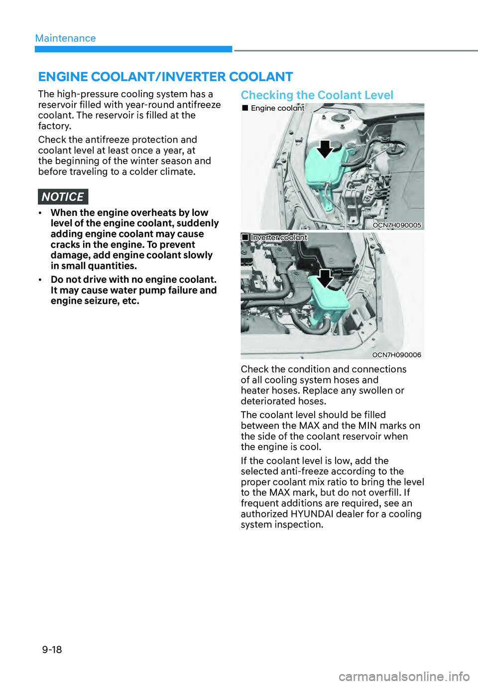
Checking the Coolant Level
OCN7H090005
„„Engine coolant
OCN7H090006
„„Inverter coolant
Check the condition and connections
of all cooling system hoses and
heater hoses. Replace any swollen or
deteriorated hoses.
The coolant level should be filled
between the MAX and the MIN marks on
the side of the coolant reservoir when
the engine is cool.
If the coolant level is low, add the
selected anti-freeze according to the
proper coolant mix ratio to bring the level
to the MAX mark, but do not overfill. If
frequent additions are required, see an
authorized HYUNDAI dealer for a cooling
system inspection.
ENGINE COOLANT/INVERTER COOLANT
Page 488 of 555
09
9-19
WARNING
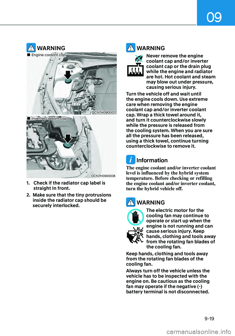
OCN7H090007
„„Engine coolant cap
OCN7H090008
„„Inverter coolant cap
1. Check if the radiator cap label is
straight In front.
2. Make sure that the tiny protrusions
inside the radiator cap should be
securely interlocked.
WARNING
Never remove the engine coolant cap and/or inverter
coolant cap or the drain plug
while the engine and radiator
are hot. Hot coolant and steam
may blow out under pressure,
causing serious injury.
Turn the vehicle off and wait until
the engine cools down. Use extreme
care when removing the engine
coolant cap and/or inverter coolant
cap. Wrap a thick towel around it,
and turn it counterclockwise slowly
while the pressure is released from
the cooling system. When you are sure
all the pressure has been released,
using a thick towel, continue turning
counterclockwise to remove it.
Information
The engine coolant and/or inverter coolant
level is influenced by the hybrid system
temperature. Before checking or refilling
the engine coolant and/or inverter coolant,
turn the hybrid vehicle off.
WARNING
The electric motor for the cooling fan may continue to
operate or start up when the
engine is not running and can
cause serious injury. Keep
hands, clothing and tools away
from the rotating fan blades of
the cooling fan.
Keep hands, clothing and tools away
from the rotating fan blades of the
cooling fan.
Always turn off the vehicle unless the
vehicle has to be inspected with the
engine on. Be cautious as the cooling
fan may operate if the negative (-)
battery terminal is not disconnected.
Page 489 of 555
Maintenance
9-20
WARNING
Make sure the coolant cap is properly
closed after refilling coolant. Otherwise
the engine could be overheated while
driving.
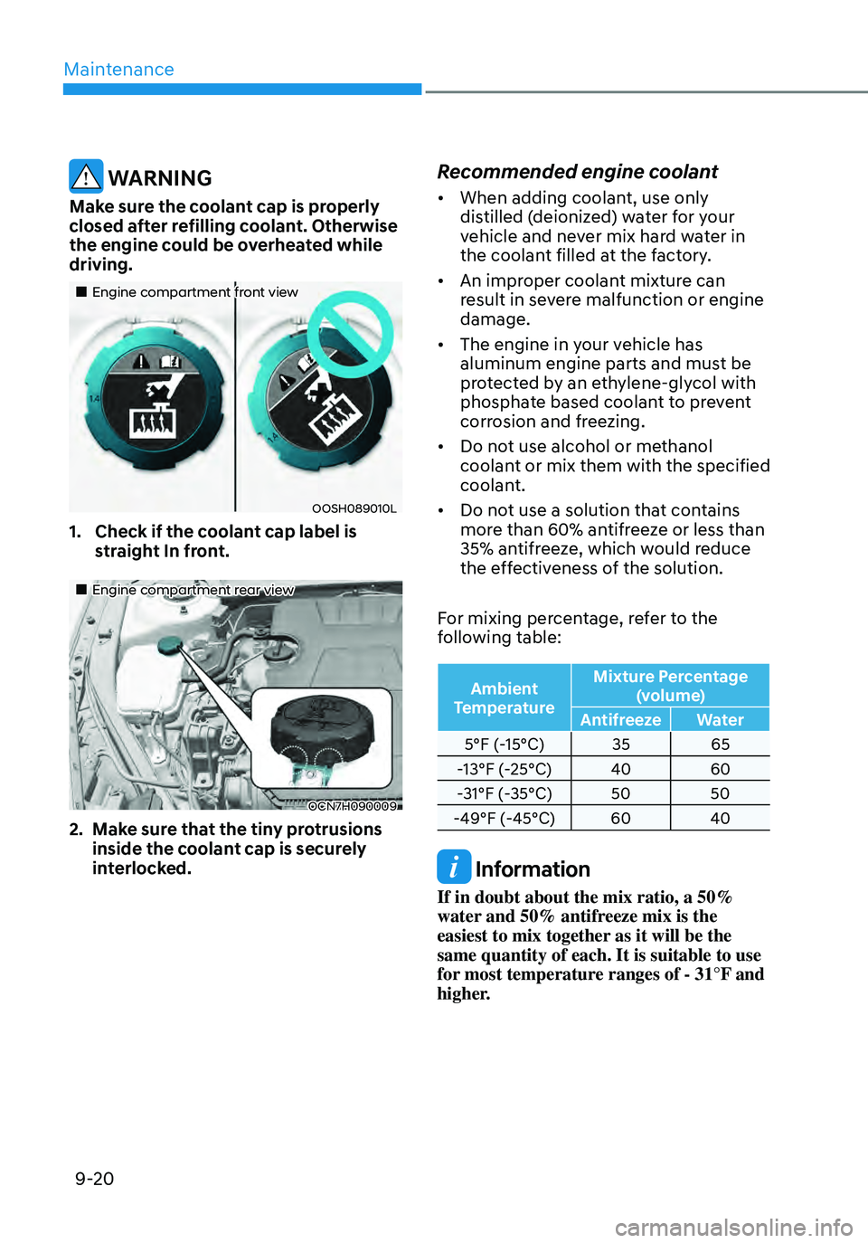
„„Engine compartment front view
OOSH089010L
1. Check if the coolant cap label is
straight In front.
„„Engine compartment rear view
OCN7H090009
2. Make sure that the tiny protrusions
inside the coolant cap is securely
interlocked.
Recommended engine coolant
• When adding coolant, use only
distilled (deionized) water for your
vehicle and never mix hard water in
the coolant filled at the factory.
• An improper coolant mixture can
result in severe malfunction or engine
damage.
• The engine in your vehicle has
aluminum engine parts and must be
protected by an ethylene-glycol with
phosphate based coolant to prevent
corrosion and freezing.
• Do not use alcohol or methanol
coolant or mix them with the specified
coolant.
• Do not use a solution that contains
more than 60% antifreeze or less than
35% antifreeze, which would reduce
the effectiveness of the solution.
For mixing percentage, refer to the
following table:
Ambient
Temperature Mixture Percentage
(volume)
Antifreeze Water
5°F (-15°C) 3565
-13°F (-25°C) 4060
-31°F (-35°C) 5050
-49°F (-45°C) 6040
Information
If in doubt about the mix ratio, a 50%
water and 50% antifreeze mix is the
easiest to mix together as it will be the
same quantity of each. It is suitable to use
for most temperature ranges of - 31°F and
higher.
Page 490 of 555
09
9-21
WARNING
The electric motor for the cooling fan may continue to
operate or start up when the
engine is not running and can
cause serious injury. Keep
hands, clothing and tools away
from the rotating fan blades of
the cooling fan.
The electric motor for the cooling
fan is controlled by engine coolant
temperature, refrigerant pressure and
vehicle speed. As the engine coolant
temperature decreases, the electric
motor will automatically shut off. This is a
normal condition.
Changing Engine Coolant
Have coolant changed by an authorized
HYUNDAI dealer according to the
Maintenance Schedule at the beginning
of this chapter.
WARNING
Do not use engine coolant or antifreeze
in the washer fluid reservoir.
Engine coolant can severely obscure
visibility when sprayed on the
windshield and may cause loss of
vehicle control resulting in an accident.
Engine coolant may also cause damage
to paint and body trim.
NOTICE
To prevent damage to engine parts, put
a thick towel around the radiator cap
before refilling the coolant to prevent
the coolant from overflowing into
engine parts, such as the alternator.
Page 493 of 555
Maintenance
9-24
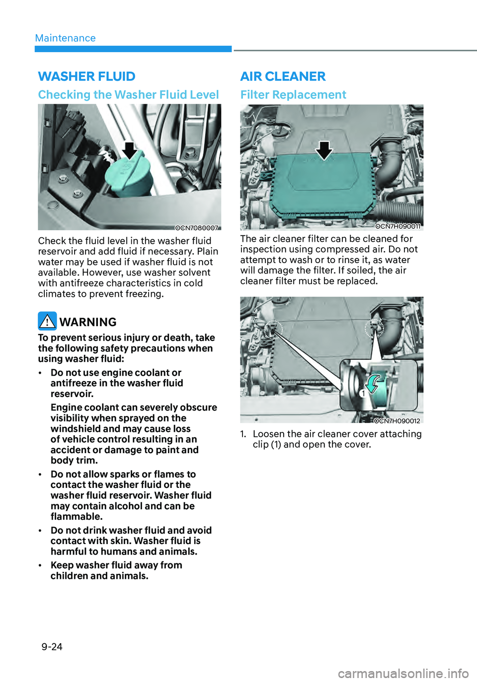
Checking the Washer Fluid Level
OCN7080007
Check the fluid level in the washer fluid
reservoir and add fluid if necessary. Plain
water may be used if washer fluid is not
available. However, use washer solvent
with antifreeze characteristics in cold
climates to prevent freezing.
WARNING
To prevent serious injury or death, take
the following safety precautions when
using washer fluid:
• Do not use engine coolant or
antifreeze in the washer fluid
reservoir.
Engine coolant can severely obscure
visibility when sprayed on the
windshield and may cause loss
of vehicle control resulting in an
accident or damage to paint and
body trim.
• Do not allow sparks or flames to
contact the washer fluid or the
washer fluid reservoir. Washer fluid
may contain alcohol and can be
flammable.
• Do not drink washer fluid and avoid
contact with skin. Washer fluid is
harmful to humans and animals.
• Keep washer fluid away from
children and animals.
WASHER FLUID
Filter Replacement
OCN7H090011
The air cleaner filter can be cleaned for
inspection using compressed air. Do not
attempt to wash or to rinse it, as water
will damage the filter. If soiled, the air
cleaner filter must be replaced.
OCN7H090012
1. Loosen the air cleaner cover attaching
clip (1) and open the cover.
AIR CLEANER
Page 507 of 555
Maintenance
9-38
Curb Weight
This means the weight of a motor vehicle
with standard and optional equipment
including the maximum capacity of fuel,
oil and coolant, but without passengers
and cargo.
DOT Markings
A code molded into the sidewall
of a tire signifying that the tire is in
compliance with the U.S. Department
of Transportation motor vehicle safety
standards. The DOT code includes the
Tire Identification Number (TIN), an
alphanumeric designator which can
also identify the tire manufacturer,
production plant, brand and date of
production.
GVWR
Gross Vehicle Weight Rating
GAWR FRT
Gross Axle Weight Rating for the Front
Axle.
GAWR RR
Gross Axle Weight Rating for the Rear
axle.
Intended Outboard Sidewall
The side of an asymmetrical tire,
that must always face outward when
mounted on a vehicle.
Kilopascal (kPa)
The metric unit for air pressure.
Light truck (LT) tire
A tire designated by its manufacturer as
primarily intended for use on lightweight
trucks or multipurpose passenger
vehicles.
Load ratings
The maximum load that a tire is rated to
carry for a given inflation pressure.
Load Index
An assigned number ranging from 1 to
279 that corresponds to the load carrying
capacity of a tire.
Maximum Inflation Pressure
The maximum air pressure to which a
cold tire may be inflated. The maximum
air pressure is molded onto the sidewall.
Maximum Load Rating
The load rating for a tire at the maximum
permissible inflation pressure for that
tire.
Maximum Loaded Vehicle Weight
The sum of curb weight; accessory
weight; vehicle capacity weight; and
production options weight.
Normal Occupant Weight
The number of occupants a vehicle
is designed to seat multiplied by 150
pounds (68 kg).
Occupant Distribution
Designated seating positions.
Outward Facing Sidewall
An asymmetrical tire has a particular
side that faces outward when mounted
on a vehicle. The outward facing
sidewall bears white lettering or bears
manufacturer, brand, and/or model
name molding that is higher or deeper
than the same moldings on the inner
facing sidewall.
Passenger (P-Metric) tire
A tire used on passenger cars and some
light duty trucks and multipurpose
vehicles.
Page 539 of 555
Maintenance
9-70
The emission control system of your
vehicle is covered by a written limited
warranty. Please see the warranty
information contained in the Owner’s
Handbook & Warranty Information
booklet in your vehicle.
Your vehicle is equipped with an
emission control system to meet all
applicable emission regulations. There
are three emission control systems, as
follows.
(1) Crankcase emission control system
(2) Evaporative emission control system
(3) Exhaust emission control system
In order to ensure the proper function
of the emission control systems, it
is recommended that you have your
vehicle inspected and maintained
by an authorized HYUNDAI dealer in
accordance with the maintenance
schedule in this manual.
NOTICE
For the Inspection and Maintenance
Test (with Electronic Stability Control
(ESC) system)
• To prevent the vehicle from misfiring
during dynamometer testing, turn
the Electronic Stability Control
(ESC) system off by pressing the ESC
switch (ESC OFF light illuminated).
• After dynamometer testing is
completed, turn the ESC system back
on by pressing the ESC switch again.
1. Crankcase Emission Control
System
The positive crankcase ventilation system
is employed to prevent air pollution
caused by blow-by gases being emitted
from the crankcase. This system supplies
fresh filtered air to the crankcase through
the air intake hose. Inside the crankcase,
the fresh air mixes with blow-by gases,
which then pass through the PCV valve
into the induction system.
2. Evaporative Emission Control
System Including Onboard
Refueling Vapor Recovery
(ORVR)
The Evaporative Emission Control System
is designed to prevent fuel vapors from
escaping into the atmosphere. The
ORVR system is designed to allow the
vapors from the fuel tank to be loaded
into a canister while refueling at the gas
station, preventing the escape of fuel
vapors into the atmosphere.
Canister
Fuel vapors generated inside the fuel
tank are absorbed and stored in the
onboard canister. When the engine is
running, the fuel vapors absorbed in the
canister are drawn into the surge tank
through the purge control solenoid valve.
Purge Control Solenoid Valve (PCSV)
The purge control solenoid valve
is controlled by the Engine Control
Module (ECM); when the engine coolant
temperature is low during idling, the
PCSV closes so that evaporated fuel
is not taken into the engine. After the
engine warms-up during ordinary
driving, the PCSV opens to introduce
evaporated fuel to the engine.
EMISSION CONTROL SYSTEM