2021 FORD SUPER DUTY brake
[x] Cancel search: brakePage 324 of 666
For Vehicles with Tremor Off-Road
Package
Your vehicle equipped with Tremor
Off-Road package is capable of traveling
through water at a maximum depth of
33 in (837 mm). When driving through
standing water do not exceed crawl speed
of
4 mph (7 km/h).
• Always determine the depth before
attempting a water crossing.
• Proceed slowly and avoid splashing
water any more than is necessary. As
the water depth increases, vehicle
speed must be reduced to avoid
potential vehicle damage.
• Be aware that obstacles and debris
may be beneath the water ’s surface.
• Keep the doors fully closed during the
water crossing.
• Upon completion of the water crossing,
slowly drive a short distance and check
the brakes for full effectiveness.
SNOW PLOWING
Ford recommends that the Super Duty
F-Series used for snow removal include
the snowplow package option.
Installing the Snowplow
Weight limits and guidelines for selecting
and installing the snowplow are in the Ford
Truck Body Builders Layout Book,
snowplow section, found at
www.fleet.ford.com/truckbbas. A typical
installation affects the following: •
Certification to government safety laws
such as occupant protection and airbag
deployment, braking, and lighting. Look
for an Alterer ’s Label on the vehicle
from the snowplow installer certifying
that the installation meets all
applicable Federal Motor Vehicle
Safety Standards (FMVSS).
• The Total Accessory Reserve Capacity
(TARC) is on the lower right side of the
vehicle ’s Safety Compliance
Certification Label. This applies to
Ford-completed vehicles of
10,000 lb
(4,536 kg) GVWR or less. This is the
weight of permanently-attached
auxiliary equipment, such as snowplow
frame-mounting hardware, that can
be added to the vehicle and satisfy
Ford compliance certification to
FMVSS. Exceeding this weight may
require the auxiliary equipment installer
additional safety certification
responsibility. The Front Accessory
Reserve Capacity (FARC) is for
customer convenience.
• Rear ballast weight behind the rear
axle may be required to prevent
exceeding the FGAWR, and provide
front-to-rear weight balance for proper
braking and steering.
• Front wheel toe may require
re-adjustment to prevent premature
uneven tire wear. Specifications are in
the Ford Workshop Manual.
• Headlight aim may require
re-adjustment.
321
Super Duty (TFE) Canada/United States of America, enUSA, Edition date: 202008, Second-Printing Driving Hints
Page 329 of 666
Vehicles Sold in Canada: Getting
Roadside Assistance
To fully assist you should you have a
vehicle concern, Ford Motor Company of
Canada, Limited offers a complimentary
roadside assistance program. This program
is eligible within Canada or the continental
United States.
The service is available 24 hours a day,
seven days a week.
This program is separate from the New
Vehicle Limited Warranty, but the coverage
is concurrent with the powertrain coverage
period of your vehicle. Canadian roadside
coverage and benefits may differ from the
U.S. coverage.
If you require more information, please call
us in Canada at 1-800-665-2006, or visit
our website at www.ford.ca.
HAZARD FLASHERS
Note:
The hazard flashers operate when
the ignition is in any position, or if the key is
not in the ignition. If used when the vehicle
is not running, the battery loses charge. As
a result, there may be insufficient power to
restart your vehicle. The flasher control is on the
instrument panel. Use your
hazard flashers when your
vehicle is creating a safety hazard for other
motorists.
• Press the flasher control and all front
and rear direction indicators flash.
• Press the button again to switch them
off. FUEL SHUTOFF WARNING: If your vehicle has been
involved in a crash, have the fuel system
checked. Failure to follow this instruction
could result in fire, personal injury or
death.
Note: When you try to restart your vehicle
after a fuel shutoff, the vehicle makes sure
that various systems are safe to restart.
Once the vehicle determines the systems
are safe, then the vehicle allows you to
restart.
Note: In the event that your vehicle does
not restart after your third attempt, contact
a qualified technician.
The fuel pump shutoff stops the flow of
fuel to the engine in the event of a
moderate to severe crash. Not every
impact causes a shutoff.
Should your vehicle shut off after a crash,
you may restart your vehicle.
If your vehicle has a key system:
1. Switch off the ignition.
2. Switch to start position.
3. Switch off the ignition.
4. Switch on the ignition to re-enable the
fuel pump.
5. If the vehicle does not start, repeat steps 1 through 4.
If your vehicle has a push button start
system:
1. Press START/STOP to switch off your
vehicle.
2. Press the brake pedal and START/STOP
to switch on your
vehicle.
3. Remove your foot from the brake pedal
and press
START/STOP to switch off
your vehicle.
326
Super Duty (TFE) Canada/United States of America, enUSA, Edition date: 202008, Second-Printing Roadside Emergencies
Page 330 of 666
4. You can attempt to start the vehicle
by pressing the brake pedal and
START/STOP, or press START/STOP
without pressing the brake pedal.
5. If the vehicle does not start, repeat steps 1 through 4.
JUMP STARTING THE VEHICLE WARNING:
Batteries normally
produce explosive gases which can
cause personal injury. Therefore, do not
allow flames, sparks or lighted
substances to come near the battery.
When working near the battery, always
shield your face and protect your eyes.
Always provide correct ventilation. WARNING:
Keep batteries out of
reach of children. Batteries contain
sulfuric acid. Avoid contact with skin,
eyes or clothing. Shield your eyes when
working near the battery to protect
against possible splashing of acid
solution. In case of acid contact with skin
or eyes, flush immediately with water for
a minimum of 15 minutes and get prompt
medical attention. If acid is swallowed,
call a physician immediately. WARNING:
Use only adequately
sized cables with insulated clamps.
Preparing Your Vehicle
Do not attempt to push-start your
automatic transmission vehicle.
Note: Attempting to push-start a vehicle
with an automatic transmission may cause
transmission damage.
Note: Use only a 12-volt supply to start your
vehicle. Note:
Do not disconnect the battery of the
disabled vehicle as this could damage the
vehicle electrical system.
Park the booster vehicle close to the hood
of the disabled vehicle, making sure the
two vehicles do not touch.
Connecting the Jumper Cables WARNING:
Do not attach the
cables to fuel lines, engine rocker covers,
the intake manifold or electrical
components as grounding points. Stay
clear of moving parts. To avoid reverse
polarity connections, make sure that you
correctly identify the positive (+) and
negative (-) terminals on both the
disabled and booster vehicles before
connecting the cables. WARNING:
Do not attach the end
of the positive cable to the studs or
L-shaped eyelet located above the
positive (+) terminal of your vehicle ’s
battery. High current may flow through
and cause damage to the fuses. WARNING: Do not connect the end
of the second cable to the negative (-)
terminal of the battery to be jumped. A
spark may cause an explosion of the
gases that surround the battery.
Note: In the illustration, the bottom vehicle
represents the booster vehicle.
327
Super Duty (TFE) Canada/United States of America, enUSA, Edition date: 202008, Second-Printing Roadside Emergencies
Page 343 of 666
Protected Component
Fuse
Rating
Fuse
Number
Power point 4.
20 A
1
Power point 3.
20 A
2
Spot light module.
10 A
3
Four-wheel drive vacuum solenoid.
10 A
4
Active front steering.
40 A
5
Snow plow.
10 A
6
Trailer tow battery charge.
30 A
7
Anti-lock brake system module.
10 A
8
Electronic power assisted steering module.
10 A
9
Trailer tow park lamps.
30 A
10
Horn.
20 A
11
Torque overlay.
30 A
12
Power sliding rear window.
30 A
13
Body control module - battery power in feed 1.
40 A
14
Passenger seat power.
30 A
15
Powertrain control module.
10 A
16
Transmission control module.
Blind spot information system.
10 A
17
Four-wheel drive module.
10 A
18
Adaptive cruise control.
5 A
19
Heated mirrors.
15 A
20
Heated rear window.
40 A
21
On-board diagnostic module.
10 A
22
Smart data link connector.
Transmission control module.
15 A
23
Driver power seat.
30 A
24
Voltage quality module.
25 A
25
340
Super Duty (TFE) Canada/United States of America, enUSA, Edition date: 202008, Second-Printing Fuses
Page 344 of 666
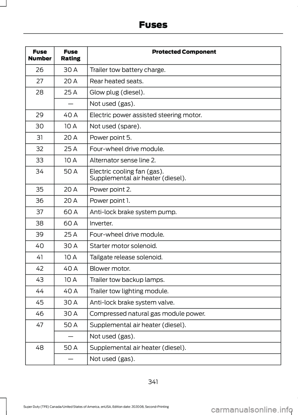
Protected Component
Fuse
Rating
Fuse
Number
Trailer tow battery charge.
30 A
26
Rear heated seats.
20 A
27
Glow plug (diesel).
25 A
28
Not used (gas).
—
Electric power assisted steering motor.
40 A
29
Not used (spare).
10 A
30
Power point 5.
20 A
31
Four-wheel drive module.
25 A
32
Alternator sense line 2.
10 A
33
Electric cooling fan (gas).
50 A
34
Supplemental air heater (diesel).
Power point 2.
20 A
35
Power point 1.
20 A
36
Anti-lock brake system pump.
60 A
37
Inverter.
60 A
38
Four-wheel drive module.
25 A
39
Starter motor solenoid.
30 A
40
Tailgate release solenoid.
10 A
41
Blower motor.
40 A
42
Trailer tow backup lamps.
10 A
43
Trailer tow lighting module.
40 A
44
Anti-lock brake system valve.
30 A
45
Compressed natural gas module power.
30 A
46
Supplemental air heater (diesel).
50 A
47
Not used (gas).
—
Supplemental air heater (diesel).
50 A
48
Not used (gas).
—
341
Super Duty (TFE) Canada/United States of America, enUSA, Edition date: 202008, Second-Printing Fuses
Page 345 of 666
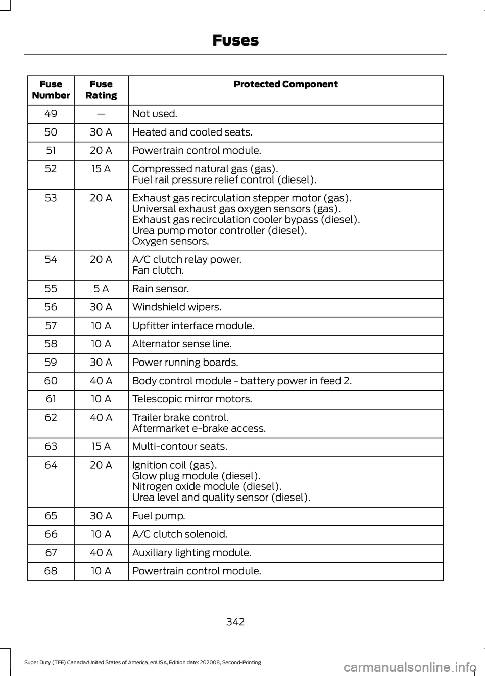
Protected Component
Fuse
Rating
Fuse
Number
Not used.
—
49
Heated and cooled seats.
30 A
50
Powertrain control module.
20 A
51
Compressed natural gas (gas).
15 A
52
Fuel rail pressure relief control (diesel).
Exhaust gas recirculation stepper motor (gas).
20 A
53
Universal exhaust gas oxygen sensors (gas).
Exhaust gas recirculation cooler bypass (diesel).
Urea pump motor controller (diesel).
Oxygen sensors.
A/C clutch relay power.
20 A
54
Fan clutch.
Rain sensor.
5 A
55
Windshield wipers.
30 A
56
Upfitter interface module.
10 A
57
Alternator sense line.
10 A
58
Power running boards.
30 A
59
Body control module - battery power in feed 2.
40 A
60
Telescopic mirror motors.
10 A
61
Trailer brake control.
40 A
62
Aftermarket e-brake access.
Multi-contour seats.
15 A
63
Ignition coil (gas).
20 A
64
Glow plug module (diesel).
Nitrogen oxide module (diesel).
Urea level and quality sensor (diesel).
Fuel pump.
30 A
65
A/C clutch solenoid.
10 A
66
Auxiliary lighting module.
40 A
67
Powertrain control module.
10 A
68
342
Super Duty (TFE) Canada/United States of America, enUSA, Edition date: 202008, Second-Printing Fuses
Page 347 of 666
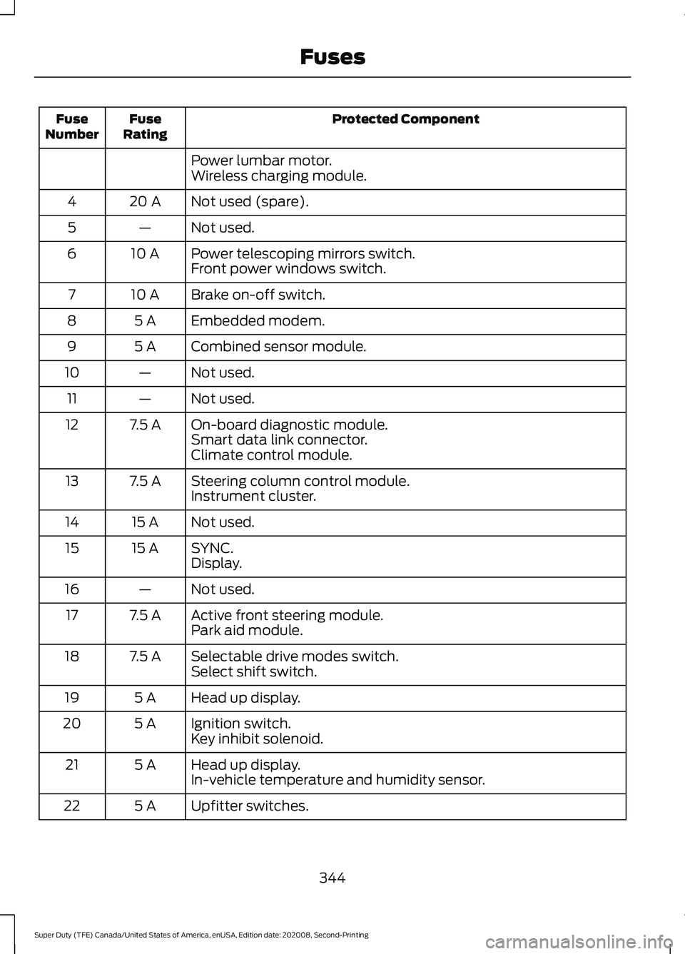
Protected Component
Fuse
Rating
Fuse
Number
Power lumbar motor.
Wireless charging module.
Not used (spare).
20 A
4
Not used.
—
5
Power telescoping mirrors switch.
10 A
6
Front power windows switch.
Brake on-off switch.
10 A
7
Embedded modem.
5 A
8
Combined sensor module.
5 A
9
Not used.
—
10
Not used.
—
11
On-board diagnostic module.
7.5 A
12
Smart data link connector.
Climate control module.
Steering column control module.
7.5 A
13
Instrument cluster.
Not used.
15 A
14
SYNC.
15 A
15
Display.
Not used.
—
16
Active front steering module.
7.5 A
17
Park aid module.
Selectable drive modes switch.
7.5 A
18
Select shift switch.
Head up display.
5 A
19
Ignition switch.
5 A
20
Key inhibit solenoid.
Head up display.
5 A
21
In-vehicle temperature and humidity sensor.
Upfitter switches.
5 A
22
344
Super Duty (TFE) Canada/United States of America, enUSA, Edition date: 202008, Second-Printing Fuses
Page 348 of 666
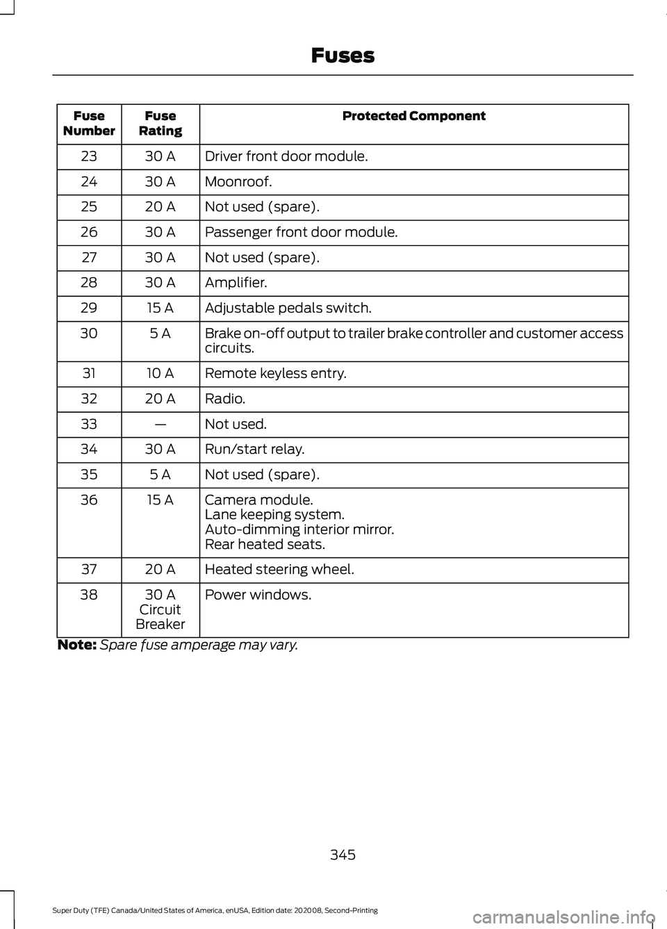
Protected Component
Fuse
Rating
Fuse
Number
Driver front door module.
30 A
23
Moonroof.
30 A
24
Not used (spare).
20 A
25
Passenger front door module.
30 A
26
Not used (spare).
30 A
27
Amplifier.
30 A
28
Adjustable pedals switch.
15 A
29
Brake on-off output to trailer brake controller and customer access
circuits.
5 A
30
Remote keyless entry.
10 A
31
Radio.
20 A
32
Not used.
—
33
Run/start relay.
30 A
34
Not used (spare).
5 A
35
Camera module.
15 A
36
Lane keeping system.
Auto-dimming interior mirror.
Rear heated seats.
Heated steering wheel.
20 A
37
Power windows.
30 A
Circuit
Breaker
38
Note: Spare fuse amperage may vary.
345
Super Duty (TFE) Canada/United States of America, enUSA, Edition date: 202008, Second-Printing Fuses