2021 FORD F650/750 oil
[x] Cancel search: oilPage 7 of 390

Fuses
Fuse Specification Chart
..........................193
Changing a Fuse ..........................................
201
Vehicle Inspection Guide
Vehicle Inspection Information .............
203
Maintenance
General Information ....................................
212
Opening and Closing the Hood ..............
213
Under Hood Overview - 6.7L Diesel ......
215
Under Hood Overview - 7.3L ....................
216
Engine Oil Dipstick - 7.3L ...........................
217
Engine Oil Dipstick - 6.7L Diesel .............
217
Engine Oil Check - 7.3L ...............................
217
Engine Oil Check - 6.7L Diesel ................
218
Changing the Engine Oil and Oil Filter ........................................................................\
.
219
Oil Change Indicator Reset .....................
220
Changing the Engine Air Filter - 6.7L Diesel ............................................................
221
Changing the Engine Air Filter - 7.3L .....
223
Draining the Fuel Filter Water Trap - 6.7L Diesel ...........................................................
225
Engine Coolant Check - 7.3L ...................
226
Engine Coolant Check - 6.7L Diesel ......
231
Automatic Transmission Fluid Check ........................................................................\
236
Brake Fluid Check ........................................
237
Power Steering Fluid Check ....................
238
Changing the 12V Battery ........................
239
Adjusting the Headlamps .......................
240
Washer Fluid Check ...................................
242
Fuel Filter - 7.3L ............................................
242
Checking the Wiper Blades .....................
242
Changing the Wiper Blades ....................
242
Removing a Headlamp .............................
243
Changing a Bulb ..........................................
243Changing the Engine-Mounted and
Diesel Fuel Conditioner Module Fuel
Filters - 6.7L Diesel .................................
244
Electrical System Inspection ..................
247
Air Induction System Inspection ...........
247
Exhaust System Inspection ....................
248
Brake System Inspection .........................
248
Axle Inspection .............................................
251
Steering System Inspection ....................
252
Suspension System Inspection .............
252
Frame and Tow Hook Inspection ..........
253
Rear Axle Fluid Check ................................
253
Spring U-Bolt Check ..................................
253
Vehicle Care
General Information ..................................
255
Cleaning Products ......................................
255
Cleaning the Exterior .................................
256
Waxing .............................................................
257
Cleaning the Engine ...................................
257
Cleaning the Windows and Wiper Blades ........................................................................\
257
Cleaning the Interior ..................................
258
Cleaning the Instrument Panel and Instrument Cluster Lens ......................
258
Repairing Minor Paint Damage .............
259
Cleaning the Wheels .................................
259
Vehicle Storage ...........................................
260
Wheels and Tires
Tire Care .........................................................
262
Using Snow Chains .....................................
277
Changing a Road Wheel ...........................
277
Technical Specifications ..........................
279
Capacities and Specifications
Engine Specifications - 6.7L Diesel .......
281
Engine Specifications - 7.3L ....................
282
Motorcraft Parts - 6.7L Diesel ................
283
4
F650750 (TBC) , enUSA, Edition date: 202010, Second-Printing Table of Contents
Page 11 of 390

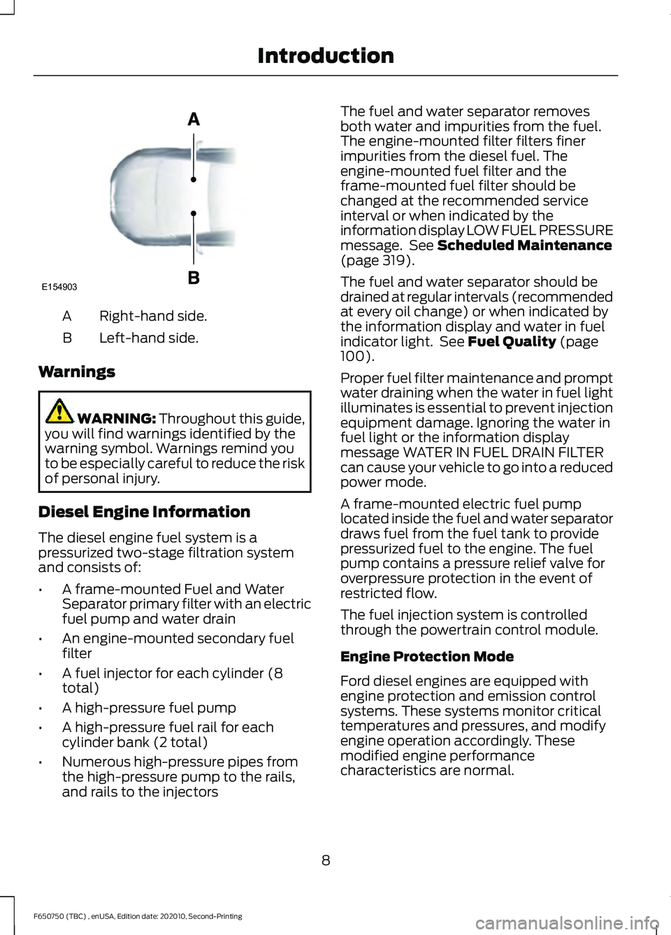
Right-hand side.
A
Left-hand side.
B
Warnings WARNING: Throughout this guide,
you will find warnings identified by the
warning symbol. Warnings remind you
to be especially careful to reduce the risk
of personal injury.
Diesel Engine Information
The diesel engine fuel system is a
pressurized two-stage filtration system
and consists of:
• A frame-mounted Fuel and Water
Separator primary filter with an electric
fuel pump and water drain
• An engine-mounted secondary fuel
filter
• A fuel injector for each cylinder (8
total)
• A high-pressure fuel pump
• A high-pressure fuel rail for each
cylinder bank (2 total)
• Numerous high-pressure pipes from
the high-pressure pump to the rails,
and rails to the injectors The fuel and water separator removes
both water and impurities from the fuel.
The engine-mounted filter filters finer
impurities from the diesel fuel. The
engine-mounted fuel filter and the
frame-mounted fuel filter should be
changed at the recommended service
interval or when indicated by the
information display LOW FUEL PRESSURE
message. See
Scheduled Maintenance
(page 319).
The fuel and water separator should be
drained at regular intervals (recommended
at every oil change) or when indicated by
the information display and water in fuel
indicator light. See
Fuel Quality (page
100).
Proper fuel filter maintenance and prompt
water draining when the water in fuel light
illuminates is essential to prevent injection
equipment damage. Ignoring the water in
fuel light or the information display
message WATER IN FUEL DRAIN FILTER
can cause your vehicle to go into a reduced
power mode.
A frame-mounted electric fuel pump
located inside the fuel and water separator
draws fuel from the fuel tank to provide
pressurized fuel to the engine. The fuel
pump contains a pressure relief valve for
overpressure protection in the event of
restricted flow.
The fuel injection system is controlled
through the powertrain control module.
Engine Protection Mode
Ford diesel engines are equipped with
engine protection and emission control
systems. These systems monitor critical
temperatures and pressures, and modify
engine operation accordingly. These
modified engine performance
characteristics are normal.
8
F650750 (TBC) , enUSA, Edition date: 202010, Second-Printing IntroductionE154903
Page 12 of 390

If these modified engine performance
characteristics persist for an extended
period and either the service engine soon
or powertrain malfunction, reduced power,
electronic throttle control light is
illuminated, have the system checked by
an authorized dealer.
Service engine soon
Powertrain malfunction, reduced
power, electronic throttle control
Diesel Lubrication System
It is important to change the engine oil at
the recommended service intervals or
when indicated by the information display
to maintain oil viscosity. Extending the oil
and filter change interval beyond the
recommended interval can negatively
affect engine performance, fuel economy
and engine life. See Engine Oil Check
(page 218).
Engine and secondary cooling system
The cooling system contains a primary
cooling loop to cool the engine and a
secondary cooling loop to cool the
transmission, charge air, and fuel. The
coolant serves three primary purposes: to
provide heat transfer, freeze point
protection, and corrosion protection using
additives.
Vehicles with diesel engines typically are
used to carry heavy loads and accumulate
mileage rapidly. These two factors may
cause the additives in the coolant to wear
out in a shorter time. You can find more
information about coolant additives and
coolant change intervals in the coolant
chapter. See
General Maintenance
Information (page 319). Operating the
engine with insufficient coolant or coolant
additive can cause severe engine damage. Selective catalytic reduction system
Your vehicle is equipped with a selective
catalytic reduction system designed to
reduce emission levels of nitrogen oxides
from the exhaust of your diesel engine. This
system relies on the use of Diesel Exhaust
Fluid (DEF) that you must replenish at
certain intervals. Failure to maintain proper
DEF levels or if the DEF becomes
contaminated will result in vehicle speed
limitations or result in your vehicle entering
an idle-only mode. See
Selective
Catalytic Reductant System (page 112).
Minor Troubleshooting Guide
If the engine won ’t crank WARNING:
Battery posts,
terminals and related accessories
contain lead and lead compounds. Wash
hands after handling.
Turn on the headlights. If the lights are dim,
do not go on at all or when the ignition is
turned to the start position, the lights
become dim or go out, the battery
connections may be loose or corroded, or
the battery may be discharged. If there is
a clicking or stuttering sound coming from
the engine compartment when you turn
the key to the start position, this may also
indicate a loose or corroded battery
connection.
Check the battery connections at the
battery posts, cable connection to the
engine grounding point and at the starter
connection.
If you suspect a discharged battery, have
it checked and corrected.
9
F650750 (TBC) , enUSA, Edition date: 202010, Second-Printing Introduction
Page 13 of 390

•
The gearshift lever must be in P (Park)
or N (Neutral) in order for the starter
to operate.
• Try operating the starter switch several
times. This operation may clean
potentially corroded contacts or make
the switch temporarily operable until
you can reach the dealer.
• If all electrical connections are tight
and you need assistance to start, See
Jump Starting the Vehicle (page 183).
If engine cranks but won ’t start
Prolonged starter cranking (in excess of 10
seconds) could cause damage to the
starter motor or the high-pressure fuel
pump.
• Check the fuel gauge. You may be out
of fuel. If the gauge shows that there
is fuel in the tank, the trouble may be
in the electrical system or the fuel
system. If equipped with an auxiliary
tank, be sure that the tank control
switch is set for the tank with fuel and
not on an empty tank.
• Leaving your ignition key turned to on
for over two minutes without starting
may make starting difficult because
the glow plugs will cease activation.
Reset the system by turning the ignition
key to off and then back to on again.
Note: If the system is out of fuel and the
engine will not start, do not continue
cranking the engine. Continued cranking can
damage the high-pressure fuel pump.
If the engine runs hot
The following could cause the engine to
overheat:
• Lack of coolant
• Dirty cooling system.
• Plugged radiator fins, A/C condenser
and/or oil cooler
• Malfunctioning fan drive •
Driving with frozen coolant
• Sticking thermostat
• Overloading or pulling heavy trailers
during hot weather
• Grill or radiator air blockage
• Slipping or missing drive belt
• Plugged or very dirty air filter
If fuses burn out WARNING: Replacement fuses and
circuit breakers must always be the
same rating as the original equipment
shown. Never replace a fuse or circuit
breaker with one of a higher rating.
Higher rated fuses or circuit breakers
could allow circuit overloading in the
event of a circuit malfunction, resulting
in severe vehicle damage or personal
injury due to fire.
Burned-out or blown fuses usually indicate
an electrical short-circuit, although a fuse
may occasionally burn out from vibration.
Insert a second fuse. If this fuse
immediately burns out and you cannot
locate the cause, return your vehicle to
your dealer for a circuit check. See
Changing a Fuse
(page 201).
Selective catalytic reduction system
speed limit and Idle-only modes
If the vehicle ’s speed is limited or in an
idle-only mode, the selective catalytic
reduction system may be limiting the
vehicle ’s functions due to low or
contaminated DEF. Check the DEF. See
Selective Catalytic Reductant System
(page
112).
SYMBOLS GLOSSARY
These are some of the symbols you may
see on your vehicle.
10
F650750 (TBC) , enUSA, Edition date: 202010, Second-Printing Introduction
Page 14 of 390

Air conditioning system
Air conditioning system lubricant
type
Anti-lock braking system
Avoid smoking, flames or sparks
Battery
Battery acid
Brake fluid - non petroleum
based
Brake system
Brake system
Cabin air filter
Check fuel cap
Child safety door lock or unlock
Child seat lower anchor
Child seat tether anchor
Cruise control Do not open when hot
Engine air filter
Engine coolant
Engine coolant temperature
Engine oil
Explosive gas
Fan warning
Fasten seatbelt
Flammable
Front airbag
Front fog lamps
Fuel pump reset
Fuse compartment
Hazard flashers
Heated rear window
11
F650750 (TBC) , enUSA, Edition date: 202010, Second-Printing IntroductionE162384 E231157 E270480 E71340 E71880 E231160 E67017
Page 23 of 390

market unique supplement, if provided,
you can properly identify those features,
recommendations and specifications that
are unique to your vehicle. This Owner
’s
Manual is written primarily for the U.S. and
Canadian Markets. Features or equipment
listed as standard may be different on units
built for export. Refer to this Owner ’s
Manual for all other required
information and warnings.
FEDERAL HIGHWAY
ADMINISTRATION
REGULATION
Regulations such as those issued by the
Federal Highway Administration or issued
pursuant to the Occupational Safety and
Health Act (OSHA), and state and local
laws and regulations may require
additional equipment for the way you
intend to use your vehicle. It is the
responsibility of the registered owner to
determine the applicability of such laws
and regulations to your intended use for
the vehicle, and to arrange for the
installation of required equipment. The
dealer has information about the
availability of equipment which can be
ordered for your vehicle.
ENTERING, EXITING OR
CLIMBING ON THIS VEHICLE WARNING: Do not carry items
while entering, exiting or climbing. Make
sure you keep a firm grip. Always face
the vehicle step and handle system while
climbing up and down. Do not climb
behind the cab unless you have three
point contact with a step and handle
system at all times. You must be careful and deliberate to
minimize the possibility of personal injury
from a slip and fall when entering, exiting
or climbing on your vehicle. Always use
the steps and assist handles before
climbing. Do not skip any steps or assist
handles. Use three point contact at all
times with at least two feet and one hand
or two hands and one foot firmly placed
during all phases of entering, exiting or
climbing. Always keep your shoe soles and
hands clean. Keep the steps and assist
handles free of snow, ice, oil, grease,
substances or debris. Be sure to take extra
care in bad weather. Avoid wearing thick
gloves. Always perform trailer hook-up
while standing on the ground.
20
F650750 (TBC) , enUSA, Edition date: 202010, Second-Printing Introduction
Page 24 of 390

PROTECTING THE
ENVIRONMENT
You should play your part in protecting the
environment. Correct vehicle usage and
the authorized disposal of waste, cleaning
and lubrication materials are significant
steps toward this aim.
For additional information about our
sustainability progress and initiatives, visit
www
.sus t ainabilit y .f or d . c om .
NOISE POLLUTION CONTROL
In order to keep to the federal exterior
noise regulations, your vehicle may be
equipped with noise emission items.
Depending on your vehicle configuration,
it may have all or some of the following
items:
Air Intake System
Inspect the air cleaner. Do not alter its
location. Do not alter inlet and outlet
piping.
Body
Inspect wheel well splash shields, cab
shields and under hood insulation for
deterioration, dislocation and orientation.
Cooling System
• Inspect the fan for blade damage. If
you find any damage, replace with the
recommended parts. Inspect for
fan-to-shroud interference and any
damage to shroud, such as cracks and
holes.
• Do not change fan ratio or alter fan
spacer dimensions and positions. •
Inspect fan clutch for proper operation.
Make sure the fan is disengaged when
cooling of the engine is not required.
• Inspect radiator shutters (if equipped)
for proper operation. The shutters
should be open during normal
operating temperatures.
Engine
Valve covers and block covers damp-out
engine mechanical noise. If they need
replacing, make sure to replace them with
the recommended parts. Check for
mechanical isolations.
Transmission Enclosure
Inspect for cracks, holes and tears. Clean
any deposits, such as oil, dirt and stones.
Exhaust System
• Inspect for leaks at various joint
connections and loose clamps.
• Perform a visual inspection for cracks
or holes in the muffler and tail pipe.
• Always use the recommended
replacement parts.
• Do not change the tail pipe elbow or
offset tail pipe orientation from the
standard position as originally received.
• To avoid abnormal changes in vehicle
sound levels, it is necessary for the
owner to perform inspections and
necessary maintenance at specified
intervals. See Scheduled
Maintenance (page 319).
21
F650750 (TBC) , enUSA, Edition date: 202010, Second-Printing Environment
Page 66 of 390

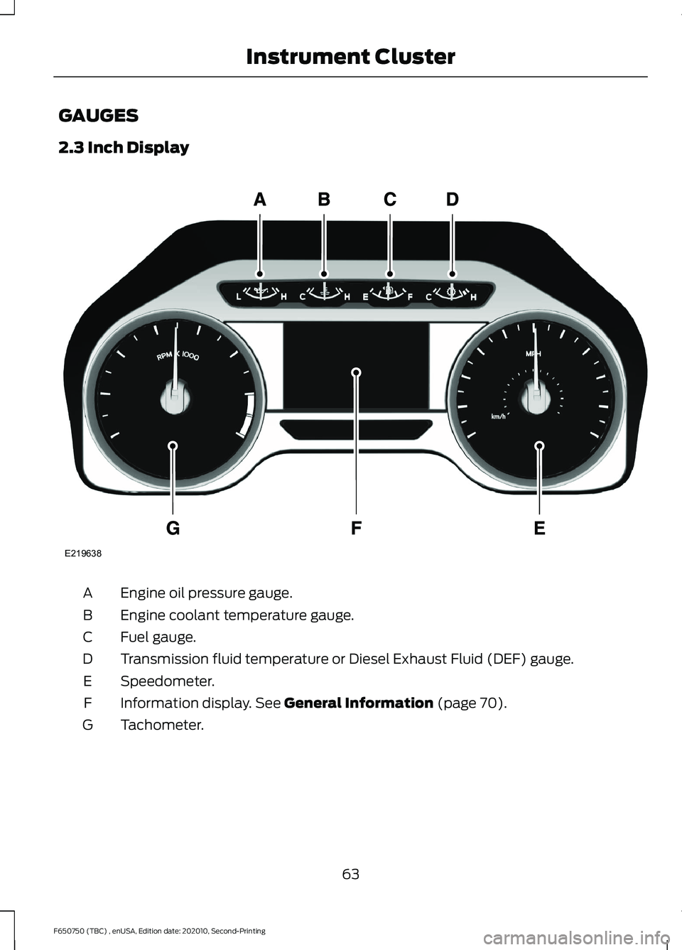
GAUGES
2.3 Inch Display
Engine oil pressure gauge.
A
Engine coolant temperature gauge.
B
Fuel gauge.
C
Transmission fluid temperature or Diesel Exhaust Fluid (DEF) gauge.
D
Speedometer.
E
Information display. See General Information (page 70).
F
Tachometer.
G
63
F650750 (TBC) , enUSA, Edition date: 202010, Second-Printing Instrument ClusterE219638