2021 FORD F650/750 fuel consumption
[x] Cancel search: fuel consumptionPage 5 of 390
Interior Mirror
..................................................62
Sun Visors ........................................................
62
Instrument Cluster
Gauges ..............................................................
63
Warning Lamps and Indicators ...............
66
Audible Warnings and Indicators ............
69
Information Displays
General Information .....................................
70
Information Messages .................................
73
Climate Control
Manual Climate Control .............................
79
Hints on Controlling the Interior Climate ........................................................................\
..
80
Heated Exterior Mirrors ................................
81
Seats
Sitting in the Correct Position ..................
82
Head Restraints .............................................
82
Manual Seats .................................................
84
Power Seats ....................................................
85
Rear Seats .......................................................
86
Front Seat Armrest .......................................
87
Rear Seat Armrest ........................................
88
Auxiliary Power Points
Auxiliary Power Points ................................
89
USB Ports
Locating the USB Ports ...............................
91
Charging a Device ..........................................
91
Storage Compartments
Overhead Console ........................................
92
Starting and Stopping the Engine
General Information .....................................
93Ignition Switch
...............................................
93
Starting a Gasoline Engine ........................
94
Starting a Diesel Engine .............................
95
Switching Off the Engine ...........................
96
Engine Idle Shutdown .................................
96
Engine Block Heater .....................................
97
Fuel and Refueling
Safety Precautions .......................................
99
Fuel Quality - Diesel ...................................
100
Fuel Quality - Gasoline ..............................
103
Running Out of Fuel - Diesel ...................
103
Running Out of Fuel - Gasoline .............
104
Refueling - Diesel ........................................
104
Refueling - Gasoline ...................................
105
Fuel Consumption ......................................
106
Fuel Tank Selector Switch .......................
108
Engine Emission Control
Emission Law ................................................
109
Catalytic Converter ......................................
110
Selective Catalytic Reductant System - Diesel .............................................................
112
Diesel Particulate Filter ..............................
116
Transmission
Automatic Transmission ...........................
122
Power Take-Off ............................................
126
Rear Axle
General Information ...................................
128
Electronic Locking Differential ...............
128
2-Speed Rear Axle ......................................
129
Brakes
General Information ...................................
130
Hints on Driving With Anti-Lock Brakes ........................................................................\
..
131
Parking Brake ..................................................
131
Hill Start Assist .............................................
134
2
F650750 (TBC) , enUSA, Edition date: 202010, Second-Printing Table of Contents
Page 109 of 390
WARNING: Do not remove the fuel
pump nozzle from its fully inserted
position when refueling.
Use the following guidelines to avoid
electrostatic charge build-up when filling
an ungrounded fuel container:
• Place approved fuel container on the
ground.
• Do not fill a fuel container while it is in
the vehicle (including the cargo area).
• Keep the fuel pump nozzle in contact
with the fuel container while filling.
• Do not use a device that would hold
the fuel pump handle in the fill position.
Fuel Filler Cap WARNING: The fuel system may
be under pressure. If you hear a hissing
sound near the fuel filler inlet, do not
refuel until the sound stops. Otherwise,
fuel may spray out, which could cause
serious personal injury. WARNING:
If you do not use the
correct fuel filler cap, excessive pressure
or vacuum in the fuel tank may damage
the fuel system or cause the fuel cap to
disengage in a crash. Failure to follow
this warning could result in serious
personal injury.
The fuel tank has a threaded fuel filler cap.
Note: If you must replace the fuel filler cap,
replace it with a fuel filler cap that is
designed for your vehicle. The vehicle
Warranty may be void for any damage to
the fuel tank or fuel system if the correct
genuine Ford, Motorcraft or other certified
fuel filler cap is not used.
When refueling the vehicle fuel tank do the
following. 1. When your vehicle has stopped, shift
into neutral (N) or park (P).
2. Apply the parking brake and switch the
ignition off.
3. Turn the fuel filler cap counterclockwise and remove it.
4. Refuel your vehicle as required.
5. Replace the fuel filler cap, turn it clockwise until you feel a strong
resistance.
If the fuel cap warning lamp or a warning
message appears in the instrument cluster,
you may not have installed the fuel filler
cap correctly.
If the fuel cap warning lamp remains on,
at the next opportunity, safely pull off of
the road, remove the fuel filler cap, align
the cap properly and reinstall it. The check
fuel cap warning lamp or warning message
may not reset immediately. It may take
several driving cycles for the indicators to
turn off. A driving cycle consists of an
engine start-up (after four or more hours
with the engine off) followed by normal
city and highway driving.
FUEL CONSUMPTION
The advertised capacity is the maximum
amount of fuel that you can add to the fuel
tank after running out of fuel. Included in
the advertised capacity is an empty
reserve. The empty reserve is an
unspecified amount of fuel that remains
in the fuel tank when the fuel gauge
indicates empty.
Note: The amount of fuel in the empty
reserve varies and should not be relied upon
to increase driving range.
106
F650750 (TBC) , enUSA, Edition date: 202010, Second-Printing Fuel and Refueling
Page 110 of 390
Filling the Fuel Tank
For consistent results when refueling:
•
Turn the ignition off before fueling; an
inaccurate reading results if the engine
is left running.
• Use the same fill rate
(low-medium-high) each time the tank
is filled.
• Allow no more than one automatic
shut-off when refueling.
Results are most accurate when the filling
method is consistent.
Calculating Fuel Economy
Do not measure fuel economy during the
first 1,000 mi (1,600 km) of driving (this is
your engine ’s break-in period). A more
accurate measurement is obtained after
2,000 mi (3,200 km)
to 3,000 mi
(4,800 km). Also, fuel expense, frequency
of fill ups or fuel gauge readings are not
accurate ways to measure fuel economy.
1. Fill the fuel tank completely and record
the initial odometer reading.
2. Each time you fill the fuel tank, record the amount of fuel added.
3. After at least three fill ups, fill the fuel tank and record the current odometer
reading.
4. Subtract your initial odometer reading from the current odometer reading.
To calculate L/100 km (liters per 100
kilometers) fuel consumption, multiply the
liters used by 100, then divide by kilometers
traveled. To calculate MPG (miles per
gallon) fuel consumption, divide miles
traveled by gallons used. Keep a record for at least one month and
record the type of driving (city or highway).
This provides an accurate estimate of your
vehicle's fuel economy under current
driving conditions. Keeping records during
summer and winter will show how
temperature impacts fuel economy.
Conditions
•
Heavily loading your vehicle reduces
fuel economy.
• Carrying unnecessary weight in your
vehicle may reduce fuel economy.
• Adding certain accessories to your
vehicle such as bug deflectors, rollbars
or light bars, running boards and ski
racks may reduce fuel economy.
• Using fuel blended with alcohol may
lower fuel economy.
• Fuel economy may decrease with lower
temperatures.
• Fuel economy may decrease when
driving short distances.
• You will get better fuel economy when
driving on flat terrain than when driving
on hilly terrain.
107
F650750 (TBC) , enUSA, Edition date: 202010, Second-Printing Fuel and Refueling
Page 112 of 390
EMISSION LAW
WARNING: Do not remove or alter
the original equipment floor covering or
insulation between it and the metal floor
of the vehicle. The floor covering and
insulation protect occupants of the
vehicle from the engine and exhaust
system heat and noise. On vehicles with
no original equipment floor covering
insulation, do not carry passengers in a
manner that permits prolonged skin
contact with the metal floor. Failure to
follow these instructions may result in
fire or personal injury.
U.S. federal laws and certain state laws
prohibit removing or rendering inoperative
emission control system components.
Similar federal or provincial laws may
apply in Canada. We do not approve of any
vehicle modification without first
determining applicable laws. Tampering with emissions
control systems including
related sensors or the Diesel
Exhaust Fluid system can result in reduced
engine power and the illumination of the
service engine soon light. Tampering With a Noise Control
System
Federal laws prohibit the following acts:
•
Removal or rendering inoperative by
any person other than for purposes of
maintenance.
• Repair or replacement of any device or
element of the design incorporated into
a new vehicle for the purpose of noise
control prior to its sale or delivery to
the ultimate purchaser or while it is in
use.
• The use of the vehicle after any person
removes or renders inoperative any
device or element of the design.
The U.S. Environmental Protection Agency
may presume to constitute tampering as
follows:
• Removal of hood blanket, fender apron
absorbers, fender apron barriers,
underbody noise shields or acoustically
absorptive material.
• Tampering or rendering inoperative the
engine speed governor, to allow engine
speed to exceed manufacturer
specifications.
If the engine does not start, runs rough,
experiences a decrease in engine
performance, experiences excess fuel
consumption or produces excessive
exhaust smoke, check for the following:
• A plugged or disconnected air inlet
system hose.
• A plugged engine air filter element.
• Water in the fuel filter and water
separator.
• A clogged fuel filter.
• Contaminated fuel.
• Air in the fuel system, due to loose
connections.
• An open or pinched sensor hose.
• Incorrect engine oil level.
109
F650750 (TBC) , enUSA, Edition date: 202010, Second-Printing Engine Emission Control
Page 179 of 390

GENERAL DRIVING POINTS
General Information
•
Accelerate smoothly and evenly. Rapid
acceleration increases fuel
consumption without increasing engine
performance.
• When approaching a hill, press the
accelerator smoothly to start the
incline at full power, and then shift
down as needed to maintain vehicle
speed.
• When going down a hill, or long steep
grades, prevent overspeeding of the
engine. Normally, choose the same
gear to descend the hill that you use to
ascend the hill. The engine governor
has no control over engine speed when
it is being pushed by a loaded vehicle.
• Do not operate in a gear that permits
an engine speed more than the
maximum governed speed or high-idle
RPM (no load).
• Always shift to a lower gear at high
altitudes to prevent engine smoking.
Backing Up WARNING: All vehicles have blind
spots. To reduce the risk of severe injury
or property damage, never move your
vehicle to the side or rear or change lanes
without being sure your way is clear on
both sides and to your rear. WARNING:
To reduce the risk of
the possibility of personal injury while
backing up the vehicle, always be sure
your vehicle ’s path is clear. Before backing up your vehicle, be sure you
can do so safely. If anything behind the cab
limits your view, do not rely on mirrors
alone to make sure that your intended path
is clear. If other people are in the vicinity,
have someone standing well behind your
vehicle and outside of your intended path
(visible through an exterior mirror) guide
you as you back up.
Although OSHA or some governmental
regulations may require the use of an
electrical or mechanical back up alarm to
warn bystanders, such an alarm does not
guarantee that the intended path is clear.
When in doubt, get out of your vehicle and
visually check the intended path is clear.
Back up slowly as to allow others time to
move, if necessary.
If you install an electrical back up alarm,
connect it to the backup lamp circuit.
Parking
WARNING:
When parking your
vehicle, do not leave the transmission in
gear; if the key is in the on position and
the vehicle rolls, the engine could start.
Failure to follow these instructions could
result in an unattended vehicle moving,
possibly causing personal injury or
property damage.
Always use the parking brake. When
parking on a grade, block the wheels and
turn the front wheels to one side so that if
your vehicle rolls, the front tires act against
the curb to stop your vehicle. The front
wheels are more effective at stopping a
rolling vehicle than the rear wheels.
176
F650750 (TBC) , enUSA, Edition date: 202010, Second-Printing Driving Hints
Page 221 of 390
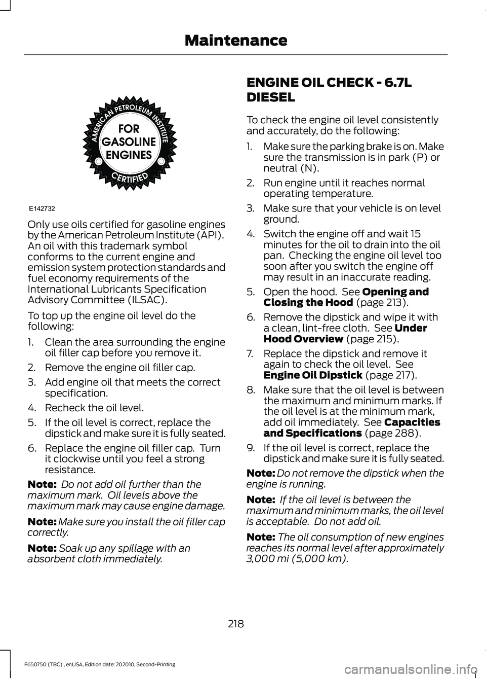
Only use oils certified for gasoline engines
by the American Petroleum Institute (API).
An oil with this trademark symbol
conforms to the current engine and
emission system protection standards and
fuel economy requirements of the
International Lubricants Specification
Advisory Committee (ILSAC).
To top up the engine oil level do the
following:
1. Clean the area surrounding the engine
oil filler cap before you remove it.
2. Remove the engine oil filler cap.
3. Add engine oil that meets the correct specification.
4. Recheck the oil level.
5. If the oil level is correct, replace the dipstick and make sure it is fully seated.
6. Replace the engine oil filler cap. Turn it clockwise until you feel a strong
resistance.
Note: Do not add oil further than the
maximum mark. Oil levels above the
maximum mark may cause engine damage.
Note: Make sure you install the oil filler cap
correctly.
Note: Soak up any spillage with an
absorbent cloth immediately. ENGINE OIL CHECK - 6.7L
DIESEL
To check the engine oil level consistently
and accurately, do the following:
1.
Make sure the parking brake is on. Make
sure the transmission is in park (P) or
neutral (N).
2. Run engine until it reaches normal operating temperature.
3. Make sure that your vehicle is on level ground.
4. Switch the engine off and wait 15 minutes for the oil to drain into the oil
pan. Checking the engine oil level too
soon after you switch the engine off
may result in an inaccurate reading.
5. Open the hood. See Opening and
Closing the Hood (page 213).
6. Remove the dipstick and wipe it with a clean, lint-free cloth. See
Under
Hood Overview (page 215).
7. Replace the dipstick and remove it again to check the oil level. See
Engine Oil Dipstick
(page 217).
8. Make sure that the oil level is between
the maximum and minimum marks. If
the oil level is at the minimum mark,
add oil immediately. See
Capacities
and Specifications (page 288).
9. If the oil level is correct, replace the dipstick and make sure it is fully seated.
Note: Do not remove the dipstick when the
engine is running.
Note: If the oil level is between the
maximum and minimum marks, the oil level
is acceptable. Do not add oil.
Note: The oil consumption of new engines
reaches its normal level after approximately
3,000 mi (5,000 km)
.
218
F650750 (TBC) , enUSA, Edition date: 202010, Second-Printing MaintenanceE142732
Page 232 of 390
Coolant Change
Change the coolant at specific mileage
intervals as listed in the scheduled
maintenance information. The information
display may display a message to change
coolant at this time. Add prediluted
coolant approved to the correct
specification. See Capacities and
Specifications (page 281).
Engine-driven Cooling Fan (Fan
Clutch)
Your vehicle comes with an engine driven
cooling fan drive, also called a fan clutch.
This fan drive changes the fan speed to
match the vehicle ’s changing cooling air
flow requirements. Fan speed, fan noise
level and fuel consumption all will increase
based on the driving conditions that
include trailer towing, hill climbing, heavy
loads, high speed and high ambient
temperature, individually or in combination.
The fan drive is designed to provide the
minimum fan speed, and resulting
minimum fan noise and fuel consumption
required to meet the ever changing vehicle
cooling air flow requirements. You will hear
the amount of fan noise increasing and
decreasing as the engine power
requirements and vehicle driving conditions
change as you drive. This is to be expected
as being normal to the operation of your
vehicle. High levels of fan noise might also
be heard when your engine is first started,
and should normally decrease after driving
for a short time.
Fail-Safe Cooling
Fail-safe cooling allows you to temporarily
drive your vehicle before any incremental
component damage occurs. The fail-safe
distance depends on ambient
temperature, vehicle load and terrain. How Fail-Safe Cooling Works
If the engine begins to overheat, the
coolant temperature gauge moves toward
the red zone: A warning lamp illuminates and
a message may appear in the
information display.
If the engine reaches a preset
over-temperature condition, the engine
switches to alternating cylinder operation.
Each disabled cylinder acts as an air pump
and cools the engine.
When this occurs, your vehicle still
operates, however:
• Engine power is limited.
• The air conditioning system turns off.
Continued operation increases the engine
temperature, causing the engine to
completely shut down. Your steering and
braking effort increases in this situation.
When the engine temperature cools, you
can re-start the engine. Have your vehicle
checked as soon as possible to minimize
engine damage.
When Fail-Safe Mode Is Activated WARNING:
Fail-safe mode is for
use during emergencies only. Operate
your vehicle in fail-safe mode only as
long as necessary to bring your vehicle
to rest in a safe location and seek
immediate repairs. When in fail-safe
mode, your vehicle will have limited
power, will not be able to maintain
229
F650750 (TBC) , enUSA, Edition date: 202010, Second-Printing Maintenance
Page 238 of 390
•
Robinair® Coolant and Battery
Refractometer 75240 –
Recommended refractometer to test
coolant concentration. (Rotunda tool
part number: ROB75240).
• Rotunda 328-R071–ELC (Antifreeze
Coolant ELC Contamination Kit)
–
Evaluates the corrosion inhibitor
additive strength.
• The first step is once the coolant
concentration is verified to be in the
range of 40 – 60%. Test the
corrosion inhibitor additive
strength. If the test results show
the cooling system does not have
excessive contamination and the
corrosion inhibitor additive strength
is sufficient then no further action
is required. If the test results for the
Engine Coolant Circuit show the
cooling system has excessive
contamination or the corrosion
inhibitor additive strength is not
sufficient then add
47 fl oz (1.4 L)
of Motorcraft Specialty Orange
Engine Coolant Revitalizer. If the
test results for the Secondary
Coolant Circuit show the cooling
system has excessive
contamination or the corrosion
inhibitor additive strength is not
sufficient then add 16 fl oz (0.47 L)
of Motorcraft Specialty Orange
Engine Coolant Revitalizer.
• Motorcraft Specialty Orange Engine
Coolant Revitalizer
– Additive to
boost the corrosion inhibitor level
based upon the test results of the
Antifreeze Coolant ELC Contamination
Kit. The Revitalizer may be added two
times over the life of the coolant. If
additional dosages are required, the
cooling system must be flushed and
refilled per the instructions in the
Workshop Manual. Make sure to follow the proper coolant and
additive specifications. See
Capacities
and Specifications (page 281).
Coolant Change
At specific mileage intervals, as listed in
the scheduled maintenance information,
the coolant should be changed. The
information display may display a message
to change coolant at this time. Add
prediluted coolant approved to the correct
specification. See
Capacities and
Specifications (page 281).
Engine-driven Cooling Fan (Fan
Clutch)
Your vehicle may have an engine driven
cooling fan drive (also called a fan clutch).
This fan drive changes the fan speed to
match the vehicle ’s changing cooling air
flow requirements. Fan speed, fan noise
level and fuel consumption all will increase
based on the driving conditions that
include trailer towing, hill climbing, heavy
loads, high speed and high ambient
temperature, individually or in combination.
The fan drive is designed to provide the
minimum fan speed (and resulting
minimum fan noise and fuel consumption)
required to meet the ever changing vehicle
cooling air flow requirements. You will hear
the amount of fan noise increasing and
decreasing as the engine power
requirements and vehicle driving conditions
change as you drive. This is to be expected
as being normal to the operation of your
vehicle. High levels of fan noise might also
be heard when your engine is first started,
and should normally decrease after driving
for a short time.
235
F650750 (TBC) , enUSA, Edition date: 202010, Second-Printing Maintenance