2021 FORD F650/750 fuses
[x] Cancel search: fusesPage 7 of 390

Fuses
Fuse Specification Chart
..........................193
Changing a Fuse ..........................................
201
Vehicle Inspection Guide
Vehicle Inspection Information .............
203
Maintenance
General Information ....................................
212
Opening and Closing the Hood ..............
213
Under Hood Overview - 6.7L Diesel ......
215
Under Hood Overview - 7.3L ....................
216
Engine Oil Dipstick - 7.3L ...........................
217
Engine Oil Dipstick - 6.7L Diesel .............
217
Engine Oil Check - 7.3L ...............................
217
Engine Oil Check - 6.7L Diesel ................
218
Changing the Engine Oil and Oil Filter ........................................................................\
.
219
Oil Change Indicator Reset .....................
220
Changing the Engine Air Filter - 6.7L Diesel ............................................................
221
Changing the Engine Air Filter - 7.3L .....
223
Draining the Fuel Filter Water Trap - 6.7L Diesel ...........................................................
225
Engine Coolant Check - 7.3L ...................
226
Engine Coolant Check - 6.7L Diesel ......
231
Automatic Transmission Fluid Check ........................................................................\
236
Brake Fluid Check ........................................
237
Power Steering Fluid Check ....................
238
Changing the 12V Battery ........................
239
Adjusting the Headlamps .......................
240
Washer Fluid Check ...................................
242
Fuel Filter - 7.3L ............................................
242
Checking the Wiper Blades .....................
242
Changing the Wiper Blades ....................
242
Removing a Headlamp .............................
243
Changing a Bulb ..........................................
243Changing the Engine-Mounted and
Diesel Fuel Conditioner Module Fuel
Filters - 6.7L Diesel .................................
244
Electrical System Inspection ..................
247
Air Induction System Inspection ...........
247
Exhaust System Inspection ....................
248
Brake System Inspection .........................
248
Axle Inspection .............................................
251
Steering System Inspection ....................
252
Suspension System Inspection .............
252
Frame and Tow Hook Inspection ..........
253
Rear Axle Fluid Check ................................
253
Spring U-Bolt Check ..................................
253
Vehicle Care
General Information ..................................
255
Cleaning Products ......................................
255
Cleaning the Exterior .................................
256
Waxing .............................................................
257
Cleaning the Engine ...................................
257
Cleaning the Windows and Wiper Blades ........................................................................\
257
Cleaning the Interior ..................................
258
Cleaning the Instrument Panel and Instrument Cluster Lens ......................
258
Repairing Minor Paint Damage .............
259
Cleaning the Wheels .................................
259
Vehicle Storage ...........................................
260
Wheels and Tires
Tire Care .........................................................
262
Using Snow Chains .....................................
277
Changing a Road Wheel ...........................
277
Technical Specifications ..........................
279
Capacities and Specifications
Engine Specifications - 6.7L Diesel .......
281
Engine Specifications - 7.3L ....................
282
Motorcraft Parts - 6.7L Diesel ................
283
4
F650750 (TBC) , enUSA, Edition date: 202010, Second-Printing Table of Contents
Page 13 of 390

•
The gearshift lever must be in P (Park)
or N (Neutral) in order for the starter
to operate.
• Try operating the starter switch several
times. This operation may clean
potentially corroded contacts or make
the switch temporarily operable until
you can reach the dealer.
• If all electrical connections are tight
and you need assistance to start, See
Jump Starting the Vehicle (page 183).
If engine cranks but won ’t start
Prolonged starter cranking (in excess of 10
seconds) could cause damage to the
starter motor or the high-pressure fuel
pump.
• Check the fuel gauge. You may be out
of fuel. If the gauge shows that there
is fuel in the tank, the trouble may be
in the electrical system or the fuel
system. If equipped with an auxiliary
tank, be sure that the tank control
switch is set for the tank with fuel and
not on an empty tank.
• Leaving your ignition key turned to on
for over two minutes without starting
may make starting difficult because
the glow plugs will cease activation.
Reset the system by turning the ignition
key to off and then back to on again.
Note: If the system is out of fuel and the
engine will not start, do not continue
cranking the engine. Continued cranking can
damage the high-pressure fuel pump.
If the engine runs hot
The following could cause the engine to
overheat:
• Lack of coolant
• Dirty cooling system.
• Plugged radiator fins, A/C condenser
and/or oil cooler
• Malfunctioning fan drive •
Driving with frozen coolant
• Sticking thermostat
• Overloading or pulling heavy trailers
during hot weather
• Grill or radiator air blockage
• Slipping or missing drive belt
• Plugged or very dirty air filter
If fuses burn out WARNING: Replacement fuses and
circuit breakers must always be the
same rating as the original equipment
shown. Never replace a fuse or circuit
breaker with one of a higher rating.
Higher rated fuses or circuit breakers
could allow circuit overloading in the
event of a circuit malfunction, resulting
in severe vehicle damage or personal
injury due to fire.
Burned-out or blown fuses usually indicate
an electrical short-circuit, although a fuse
may occasionally burn out from vibration.
Insert a second fuse. If this fuse
immediately burns out and you cannot
locate the cause, return your vehicle to
your dealer for a circuit check. See
Changing a Fuse
(page 201).
Selective catalytic reduction system
speed limit and Idle-only modes
If the vehicle ’s speed is limited or in an
idle-only mode, the selective catalytic
reduction system may be limiting the
vehicle ’s functions due to low or
contaminated DEF. Check the DEF. See
Selective Catalytic Reductant System
(page
112).
SYMBOLS GLOSSARY
These are some of the symbols you may
see on your vehicle.
10
F650750 (TBC) , enUSA, Edition date: 202010, Second-Printing Introduction
Page 174 of 390
TOWING A TRAILER
WARNING: Do not exceed
the GVWR or the GAWR
specified on the certification
label. WARNING:
Towing trailers
beyond the maximum
recommended gross trailer
weight exceeds the limit of the
vehicle and could result in engine
damage, transmission damage,
structural damage, loss of
vehicle control, vehicle rollover
and personal injury.
Your vehicle may have electrical
items, such as fuses or relays,
related to towing. See
Fuses
(page 193).
Your vehicle's load capacity
designation is by weight, not by
volume, so you cannot necessarily
use all available space when
loading a vehicle.
Towing a trailer places an extra
load on your vehicle's engine,
transmission, axle, brakes, tires
and suspension. Inspect these
components periodically during,
and after, any towing operation. Load Placement
To help minimize how trailer
movement affects your vehicle
when driving:
•
Load the heaviest items closest
to the trailer floor.
• Load the heaviest items
centered between the left and
right side trailer tires.
• Load the heaviest items above
the trailer axles or just slightly
forward toward the trailer
tongue. Do not allow the final
trailer tongue weight to go
above or below 10-15% of the
loaded trailer weight.
When driving with a trailer or
payload, a slight takeoff vibration
or shudder may be present due to
the increased payload weight.
Additional information regarding
proper trailer loading and setting
your vehicle up for towing is
located in another chapter of this
manual. See
Load Limit (page
168).
You can also find information in
the
RV & Trailer Towing Guide
available at your authorized
dealer, or online. RV & Trailer Towing Guide Online
http://www.fleet.ford.com/towing-guides/
Website
171
F650750 (TBC) , enUSA, Edition date: 202010, Second-Printing Towing
Page 186 of 390
JUMP STARTING THE VEHICLE
WARNING: Batteries normally
produce explosive gases which can
cause personal injury. Therefore, do not
allow flames, sparks or lighted
substances to come near the battery.
When working near the battery, always
shield your face and protect your eyes.
Always provide correct ventilation. WARNING:
Keep batteries out of
reach of children. Batteries contain
sulfuric acid. Avoid contact with skin,
eyes or clothing. Shield your eyes when
working near the battery to protect
against possible splashing of acid
solution. In case of acid contact with skin
or eyes, flush immediately with water for
a minimum of 15 minutes and get prompt
medical attention. If acid is swallowed,
call a physician immediately. WARNING:
Use only adequately
sized cables with insulated clamps.
Preparing Your Vehicle
Do not attempt to push-start your
automatic transmission vehicle.
Note: Attempting to push-start a vehicle
with an automatic transmission may cause
transmission damage.
Note: Use only a 12-volt supply to start your
vehicle.
Note: Do not disconnect the battery of the
disabled vehicle as this could damage the
vehicle electrical system.
Park the booster vehicle close to the hood
of the disabled vehicle, making sure the
two vehicles do not touch. Connecting the Jumper Cables WARNING:
Do not attach the
cables to fuel lines, engine rocker covers,
the intake manifold or electrical
components as grounding points. Stay
clear of moving parts. To avoid reverse
polarity connections, make sure that you
correctly identify the positive (+) and
negative (-) terminals on both the
disabled and booster vehicles before
connecting the cables. WARNING:
Do not attach the end
of the positive cable to the studs or
L-shaped eyelet located above the
positive (+) terminal of your vehicle ’s
battery. High current may flow through
and cause damage to the fuses. WARNING: Do not connect the end
of the second cable to the negative (-)
terminal of the battery to be jumped. A
spark may cause an explosion of the
gases that surround the battery.
Note: In the illustration, the bottom vehicle
represents the booster vehicle.
183
F650750 (TBC) , enUSA, Edition date: 202010, Second-Printing Roadside Emergencies
Page 196 of 390
FUSE SPECIFICATION CHART
Engine Compartment Fuse Box
WARNING: Always disconnect the
battery before servicing high current
fuses. WARNING:
To reduce risk of
electrical shock, always replace the
cover to the power distribution box
before reconnecting the battery or
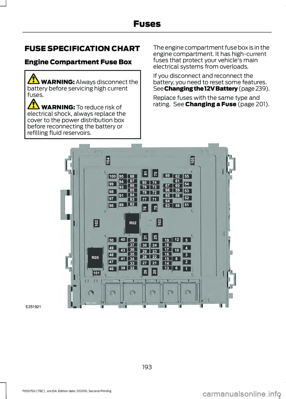
refilling fluid reservoirs. The engine compartment fuse box is in the
engine compartment. It has high-current
fuses that protect your vehicle's main
electrical systems from overloads.
If you disconnect and reconnect the
battery, you need to reset some features.
See
Changing the 12V Battery (page 239).
Replace fuses with the same type and
rating. See
Changing a Fuse (page 201). 193
F650750 (TBC) , enUSA, Edition date: 202010, Second-Printing FusesE251921
Page 197 of 390
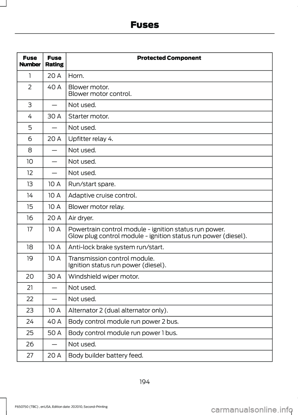
Protected Component
Fuse
Rating
Fuse
Number
Horn.
20 A
1
Blower motor.
40 A
2
Blower motor control.
Not used.
—
3
Starter motor.
30 A
4
Not used.
—
5
Upfitter relay 4.
20 A
6
Not used.
—
8
Not used.
—
10
Not used.
—
12
Run/start spare.
10 A
13
Adaptive cruise control.
10 A
14
Blower motor relay.
10 A
15
Air dryer.
20 A
16
Powertrain control module - ignition status run power.
10 A
17
Glow plug control module - ignition status run power (diesel).
Anti-lock brake system run/start.
10 A
18
Transmission control module.
10 A
19
Ignition status run power (diesel).
Windshield wiper motor.
30 A
20
Not used.
—
21
Not used.
—
22
Alternator 2 (dual alternator only).
10 A
23
Body control module run power 2 bus.
40 A
24
Body control module run power 1 bus.
50 A
25
Not used.
—
26
Body builder battery feed.
20 A
27
194
F650750 (TBC) , enUSA, Edition date: 202010, Second-Printing Fuses
Page 198 of 390
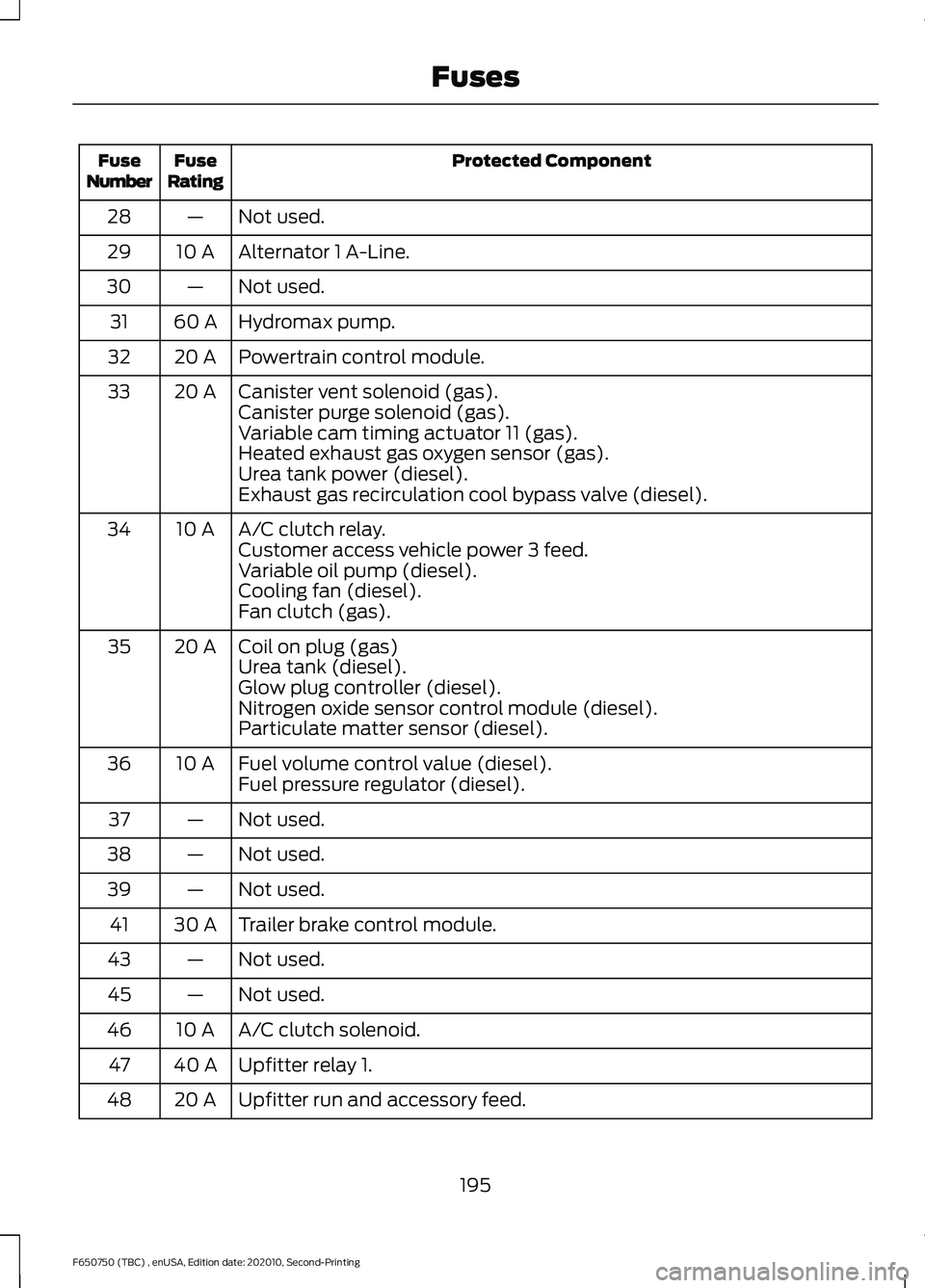
Protected Component
Fuse
Rating
Fuse
Number
Not used.
—
28
Alternator 1 A-Line.
10 A
29
Not used.
—
30
Hydromax pump.
60 A
31
Powertrain control module.
20 A
32
Canister vent solenoid (gas).
20 A
33
Canister purge solenoid (gas).
Variable cam timing actuator 11 (gas).
Heated exhaust gas oxygen sensor (gas).
Urea tank power (diesel).
Exhaust gas recirculation cool bypass valve (diesel).
A/C clutch relay.
10 A
34
Customer access vehicle power 3 feed.
Variable oil pump (diesel).
Cooling fan (diesel).
Fan clutch (gas).
Coil on plug (gas)
20 A
35
Urea tank (diesel).
Glow plug controller (diesel).
Nitrogen oxide sensor control module (diesel).
Particulate matter sensor (diesel).
Fuel volume control value (diesel).
10 A
36
Fuel pressure regulator (diesel).
Not used.
—
37
Not used.
—
38
Not used.
—
39
Trailer brake control module.
30 A
41
Not used.
—
43
Not used.
—
45
A/C clutch solenoid.
10 A
46
Upfitter relay 1.
40 A
47
Upfitter run and accessory feed.
20 A
48
195
F650750 (TBC) , enUSA, Edition date: 202010, Second-Printing Fuses
Page 199 of 390

Protected Component
Fuse
Rating
Fuse
Number
Pump electronics module (gas).
30 A
49
Fuel pump (diesel).
Injector power (gas).
15 A
50
Power point #1.
20 A
51
Not used.
—
52
Trailer tow park lamp.
30 A
53
Not used.
—
54
Upfitter relay 3.
20 A
55
Not used.
—
56
USB power.
5 A
58
Not used.
—
59
Dual fuel tank selector switch (diesel).
10 A
60
Not used.
—
61
Not used.
—
62
Driver seat compressor.
20 A
63
Passenger seat compressor.
20 A
64
Not used.
—
65
Four pack solenoid differential lock.
10 A
66
Hydromax relay power.
10 A
67
Not used.
—
69
Inverter.
40 A
70
Anti-lock brake system valves.
30 A
71
Brake on-off switch (hydraulic brakes).
10 A
72
Stop lamp air pressure switch 1 and 2 (air brakes).
Not used.
—
73
Heated mirror.
15 A
74
Not used.
—
75
196
F650750 (TBC) , enUSA, Edition date: 202010, Second-Printing Fuses