2021 FORD F650/750 bulb
[x] Cancel search: bulbPage 7 of 390

Fuses
Fuse Specification Chart
..........................193
Changing a Fuse ..........................................
201
Vehicle Inspection Guide
Vehicle Inspection Information .............
203
Maintenance
General Information ....................................
212
Opening and Closing the Hood ..............
213
Under Hood Overview - 6.7L Diesel ......
215
Under Hood Overview - 7.3L ....................
216
Engine Oil Dipstick - 7.3L ...........................
217
Engine Oil Dipstick - 6.7L Diesel .............
217
Engine Oil Check - 7.3L ...............................
217
Engine Oil Check - 6.7L Diesel ................
218
Changing the Engine Oil and Oil Filter ........................................................................\
.
219
Oil Change Indicator Reset .....................
220
Changing the Engine Air Filter - 6.7L Diesel ............................................................
221
Changing the Engine Air Filter - 7.3L .....
223
Draining the Fuel Filter Water Trap - 6.7L Diesel ...........................................................
225
Engine Coolant Check - 7.3L ...................
226
Engine Coolant Check - 6.7L Diesel ......
231
Automatic Transmission Fluid Check ........................................................................\
236
Brake Fluid Check ........................................
237
Power Steering Fluid Check ....................
238
Changing the 12V Battery ........................
239
Adjusting the Headlamps .......................
240
Washer Fluid Check ...................................
242
Fuel Filter - 7.3L ............................................
242
Checking the Wiper Blades .....................
242
Changing the Wiper Blades ....................
242
Removing a Headlamp .............................
243
Changing a Bulb ..........................................
243Changing the Engine-Mounted and
Diesel Fuel Conditioner Module Fuel
Filters - 6.7L Diesel .................................
244
Electrical System Inspection ..................
247
Air Induction System Inspection ...........
247
Exhaust System Inspection ....................
248
Brake System Inspection .........................
248
Axle Inspection .............................................
251
Steering System Inspection ....................
252
Suspension System Inspection .............
252
Frame and Tow Hook Inspection ..........
253
Rear Axle Fluid Check ................................
253
Spring U-Bolt Check ..................................
253
Vehicle Care
General Information ..................................
255
Cleaning Products ......................................
255
Cleaning the Exterior .................................
256
Waxing .............................................................
257
Cleaning the Engine ...................................
257
Cleaning the Windows and Wiper Blades ........................................................................\
257
Cleaning the Interior ..................................
258
Cleaning the Instrument Panel and Instrument Cluster Lens ......................
258
Repairing Minor Paint Damage .............
259
Cleaning the Wheels .................................
259
Vehicle Storage ...........................................
260
Wheels and Tires
Tire Care .........................................................
262
Using Snow Chains .....................................
277
Changing a Road Wheel ...........................
277
Technical Specifications ..........................
279
Capacities and Specifications
Engine Specifications - 6.7L Diesel .......
281
Engine Specifications - 7.3L ....................
282
Motorcraft Parts - 6.7L Diesel ................
283
4
F650750 (TBC) , enUSA, Edition date: 202010, Second-Printing Table of Contents
Page 8 of 390
Motorcraft Parts - 7.3L
..............................285
Vehicle Identification Number ..............
286
Transmission Code Designation ...........
287
Capacities and Specifications - 6.7L Diesel ..........................................................
288
Capacities and Specifications - 7.3L ........................................................................\
297
Bulb Specification Chart .........................
305
Connected Vehicle
Connected Vehicle Requirements .......
306
Connected Vehicle Limitations .............
306
Connecting the Vehicle to a Mobile Network .....................................................
306
Connected Vehicle – Troubleshooting .......................................................................
306
Audio System
General Information ..................................
307
Audio Unit ......................................................
307
Digital Radio ..................................................
310
Connecting a Bluetooth® Device ..........
312
Streaming Bluetooth Audio .....................
313
Playing Media From a USB Device ........
313
Using Voice Recognition ...........................
313
Accessories
Auxiliary Switches .......................................
315
Ford Protect
Ford Protect ...................................................
317
Scheduled Maintenance
General Maintenance Information .......
319
Normal Scheduled Maintenance ..........
323
Special Operating Conditions Scheduled Maintenance ............................................
329
Scheduled Maintenance Record ...........
337
Appendices
Electromagnetic Compatibility .............
348End User License Agreement
..................
351
Declaration of Conformity .......................
376
5
F650750 (TBC) , enUSA, Edition date: 202010, Second-Printing Table of Contents
Page 69 of 390
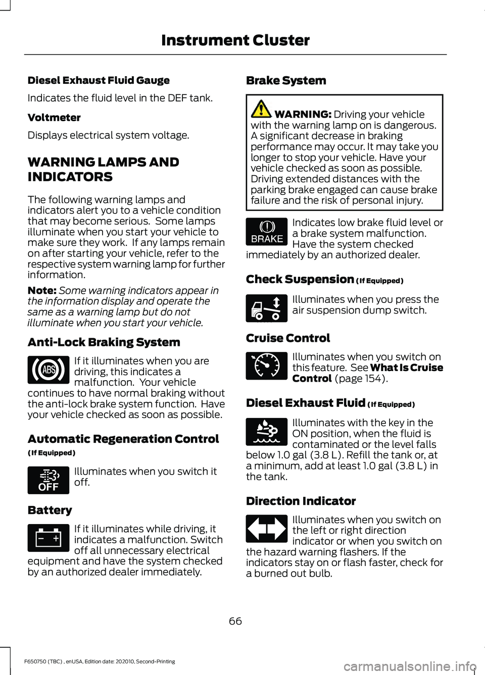
Diesel Exhaust Fluid Gauge
Indicates the fluid level in the DEF tank.
Voltmeter
Displays electrical system voltage.
WARNING LAMPS AND
INDICATORS
The following warning lamps and
indicators alert you to a vehicle condition
that may become serious. Some lamps
illuminate when you start your vehicle to
make sure they work. If any lamps remain
on after starting your vehicle, refer to the
respective system warning lamp for further
information.
Note:
Some warning indicators appear in
the information display and operate the
same as a warning lamp but do not
illuminate when you start your vehicle.
Anti-Lock Braking System If it illuminates when you are
driving, this indicates a
malfunction. Your vehicle
continues to have normal braking without
the anti-lock brake system function. Have
your vehicle checked as soon as possible.
Automatic Regeneration Control
(If Equipped) Illuminates when you switch it
off.
Battery If it illuminates while driving, it
indicates a malfunction. Switch
off all unnecessary electrical
equipment and have the system checked
by an authorized dealer immediately. Brake System WARNING: Driving your vehicle
with the warning lamp on is dangerous.
A significant decrease in braking
performance may occur. It may take you
longer to stop your vehicle. Have your
vehicle checked as soon as possible.
Driving extended distances with the
parking brake engaged can cause brake
failure and the risk of personal injury. Indicates low brake fluid level or
a brake system malfunction.
Have the system checked
immediately by an authorized dealer.
Check Suspension
(If Equipped) Illuminates when you press the
air suspension dump switch.
Cruise Control Illuminates when you switch on
this feature. See What Is Cruise
Control
(page 154).
Diesel Exhaust Fluid
(If Equipped) Illuminates with the key in the
ON position, when the fluid is
contaminated or the level falls
below
1.0 gal (3.8 L). Refill the tank or, at
a minimum, add at least 1.0 gal (3.8 L) in
the tank.
Direction Indicator Illuminates when you switch on
the left or right direction
indicator or when you switch on
the hazard warning flashers. If the
indicators stay on or flash faster, check for
a burned out bulb.
66
F650750 (TBC) , enUSA, Edition date: 202010, Second-Printing Instrument Cluster E208811 E209041 E208808 E71340 E163176
Page 71 of 390

the parking brake, this may indicate a
failure in the parking brake system. Have
the system checked as soon as possible.
Driving extended distances with the
parking brake engaged can cause brake
failure and the risk of personal injury.
Parking Lamps
Illuminates when you switch the
low beam headlamps or the
parking lamps on.
Powertrain Malfunction/Reduced
Power/Electronic Throttle Control
(If Equipped) Illuminates in the event of a
powertrain fault. Contact an
authorized dealer as soon as
possible.
Service Engine Soon If it illuminates when the engine
is running, the on board
diagnostics system notifies you
that the emission control system requires
service.
If it flashes, engine misfire may be
occurring. Increased exhaust gas
temperatures could damage the catalytic
converter or other vehicle components.
Avoid heavy acceleration and deceleration
and have your vehicle serviced
immediately.
It illuminates when you switch the ignition
on prior to engine start to check the bulb
and to indicate whether your vehicle is
ready for Inspection and Maintenance
(I/M) testing. Normally, it illuminates until the engine is
cranked and automatically turns off if no
malfunctions are present. However, if after
15 seconds it flashes eight times, this
indicates that your vehicle is not ready for
Inspection and Maintenance (I/M) testing.
See Catalytic Converter (page 110).
Stability Control Indicator (If Equipped) Flashes during operation.
If it does not illuminate when you switch
the ignition on, or remains on when the
engine is running, this indicates a
malfunction. Have your vehicle checked
as soon as possible.
Traction Control Indicator It flashes during a traction
control event.
If it does not illuminate when you switch
the ignition on, or remains on when the
engine is running, this indicates a
malfunction. Have your vehicle checked
as soon as possible.
Traction Control System Off Illuminates when you switch the
system off.
Trailer Anti-Lock Brake System
(ABS) Illuminates briefly when you
switch on the ignition, and only
when a PLC trailer or a PLC
diagnostic tool is connected. If the light
fails to illuminate, remains on after you
start the vehicle or continues to flash, have
the system serviced immediately.
68
F650750 (TBC) , enUSA, Edition date: 202010, Second-Printing Instrument Cluster E138639 E138639 E194301 E209040
Page 114 of 390

Illumination of the service engine soon
indicator, charging system warning light or
the temperature warning light, fluid leaks,
strange odors, smoke or loss of engine
power could indicate that the emission
control system is not working properly.
An improperly operating or damaged
exhaust system may allow exhaust to
enter the vehicle. Have a damaged or
improperly operating exhaust system
inspected and repaired immediately.
Do not make any unauthorized changes to
your vehicle or engine. By law, vehicle
owners and anyone who manufactures,
repairs, services, sells, leases, trades
vehicles, or supervises a fleet of vehicles
are not permitted to intentionally remove
an emission control device or prevent it
from working. Information about your
vehicle
’s emission system is on the Vehicle
Emission Control Information Decal
located on or near the engine. This decal
also lists engine displacement.
Please consult your warranty information
for complete details.
On-Board Diagnostics (OBD-II)
Your vehicle has a computer known as the
on-board diagnostics system (OBD-II) that
monitors the engine ’s emission control
system. The system protects the
environment by making sure that your
vehicle continues to meet government
emission standards. The OBD-II system
also assists a service technician in properly
servicing your vehicle. When the service engine soon
indicator illuminates, the OBD-II
system has detected a
malfunction. Temporary malfunctions may
cause the service engine soon indicator to
illuminate. Examples are: 1. Your vehicle has run out of fuel
—the
engine may misfire or run poorly.
2. Poor fuel quality or water in the fuel —the engine may misfire or run
poorly.
3. The fuel fill inlet may not have closed properly. See Refueling (page 104).
4. Driving through deep water —the
electrical system may be wet.
You can correct these temporary
malfunctions by filling the fuel tank with
good quality fuel, properly closing the fuel
fill inlet or letting the electrical system dry
out. After three driving cycles without these
or any other temporary malfunctions
present, the service engine soon indicator
should stay off the next time you start the
engine. A driving cycle consists of a cold
engine startup followed by mixed city and
highway driving. No additional vehicle
service is required.
If the service engine soon indicator remains
on, have your vehicle serviced at the first
available opportunity. Although some
malfunctions detected by the OBD-II may
not have symptoms that are apparent,
continued driving with the service engine
soon indicator on can result in increased
emissions, lower fuel economy, reduced
engine and transmission smoothness and
lead to more costly repairs.
Readiness for Inspection and
Maintenance (I/M) Testing
Some state and provincial and local
governments may have
Inspection/Maintenance (I/M) programs
to inspect the emission control equipment
on your vehicle. Failure to pass this
inspection could prevent you from getting
a vehicle registration. If the service engine soon
indicator is on or the bulb does
not work, your vehicle may need
service. See On-Board Diagnostics.
111
F650750 (TBC) , enUSA, Edition date: 202010, Second-Printing Engine Emission Control
Page 115 of 390
Your vehicle may not pass the I/M test if
the service engine soon indicator is on or
not working properly (bulb is burned out),
or if the OBD-II system has determined
that some of the emission control systems
have not been properly checked. In this
case, the vehicle is not ready for I/M
testing.
If the vehicle
’s engine or transmission has
just been serviced, or the battery has
recently run down or been replaced, the
OBD-II system may indicate that the
vehicle is not ready for I/M testing. To
determine if the vehicle is ready for I/M
testing, turn the ignition key to the on
position for 15 seconds without cranking
the engine. If the service engine soon
indicator blinks eight times, it means that
the vehicle is not ready for I/M testing; if
the service engine soon indicator stays on
solid, it means that your vehicle is ready
for I/M testing.
The OBD-II system checks the emission
control system during normal driving. A
complete check may take several days.
If the vehicle is not ready for I/M testing,
you can perform the following driving cycle
consisting of mixed city and highway
driving:
1. 15 minutes of steady driving on an expressway or highway followed by 20
minutes of stop-and-go driving with at
least four 30-second idle periods.
2. Allow your vehicle to sit for at least eight hours with the ignition off. Then,
start the vehicle and complete the
above driving cycle. The vehicle must
warm up to its normal operating
temperature. Once started, do not turn
off the vehicle until the above driving
cycle is complete.
If the vehicle is still not ready for I/M
testing, you need to repeat the above
driving cycle. SELECTIVE CATALYTIC
REDUCTANT SYSTEM - DIESEL
Your vehicle may have a selective catalytic
reduction system. The system helps reduce
emission levels of oxides of nitrogen from
the exhaust system. The system
automatically injects diesel exhaust fluid
into the exhaust system to enable correct
selective catalytic reduction system
function.
Note:
Selective catalytic reduction systems
are not fitted to vehicles in markets where
only high-sulfur diesel fuel is available.
Diesel Exhaust Fluid Level
In order for the system to operate correctly
you must maintain the diesel exhaust fluid
level.
The system has a sensor to monitor fluid
level and quality/concentration. A warning
message appears in the information
display when the diesel exhaust fluid level
is low. If a warning message appears, refill
the diesel exhaust fluid tank as soon as
possible. See Information Messages
(page 73).
Filling the Diesel Exhaust Fluid
Tank WARNING:
Keep diesel exhaust
fluid out of reach of children. Avoid
contact with skin, eyes or clothing. In
case of contact with your eyes, flush
immediately with water and get prompt
medical attention. In case of contact
with your skin, clean immediately with
soap and water. If you swallow any
diesel exhaust fluid, drink plenty of
water, call a physician immediately.
112
F650750 (TBC) , enUSA, Edition date: 202010, Second-Printing Engine Emission Control
Page 244 of 390
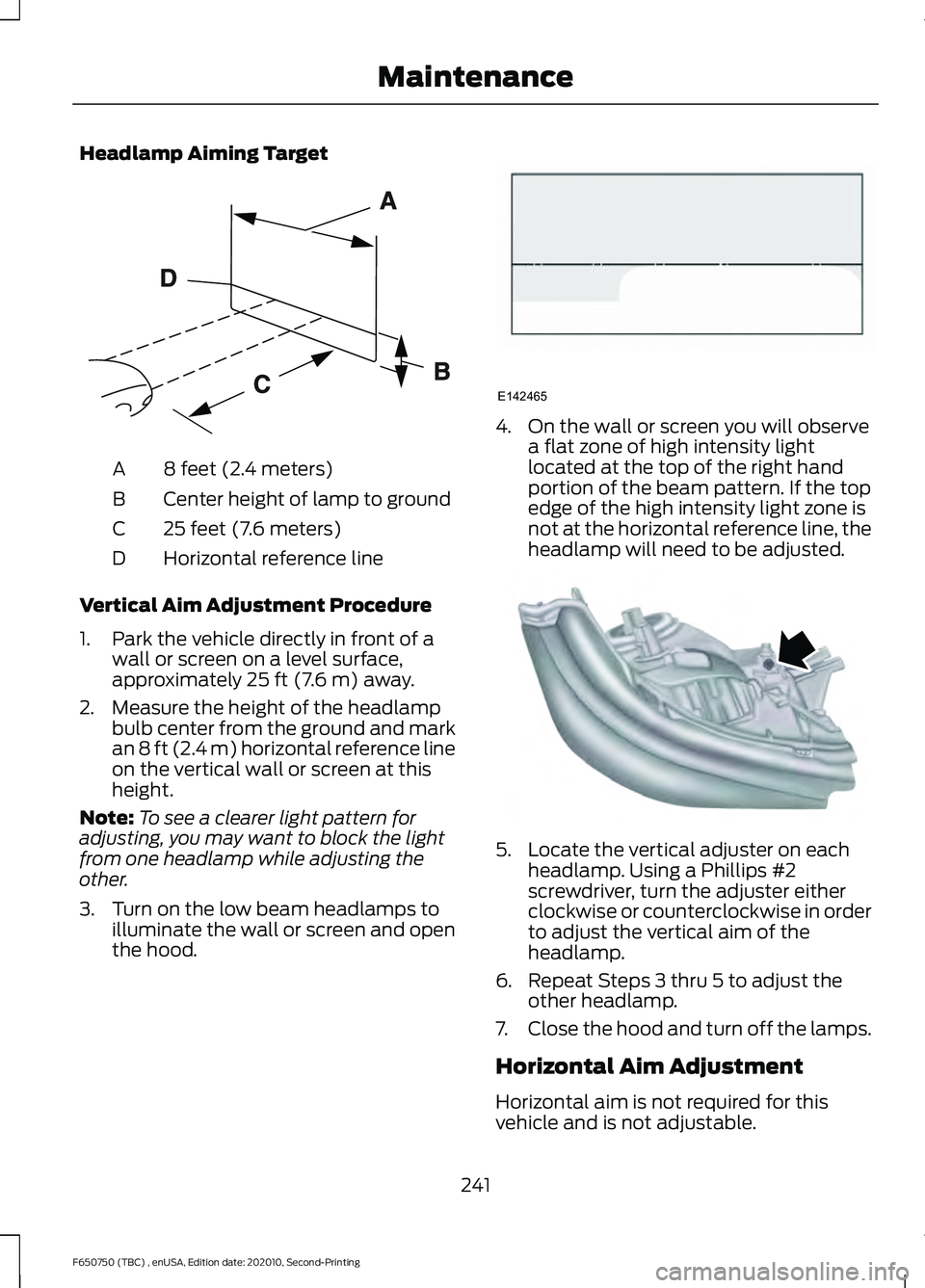
Headlamp Aiming Target
8 feet (2.4 meters)
A
Center height of lamp to ground
B
25 feet (7.6 meters)
C
Horizontal reference line
D
Vertical Aim Adjustment Procedure
1. Park the vehicle directly in front of a wall or screen on a level surface,
approximately 25 ft (7.6 m) away.
2. Measure the height of the headlamp bulb center from the ground and mark
an
8 ft (2.4 m) horizontal reference line
on the vertical wall or screen at this
height.
Note: To see a clearer light pattern for
adjusting, you may want to block the light
from one headlamp while adjusting the
other.
3. Turn on the low beam headlamps to illuminate the wall or screen and open
the hood. 4. On the wall or screen you will observe
a flat zone of high intensity light
located at the top of the right hand
portion of the beam pattern. If the top
edge of the high intensity light zone is
not at the horizontal reference line, the
headlamp will need to be adjusted. 5. Locate the vertical adjuster on each
headlamp. Using a Phillips #2
screwdriver, turn the adjuster either
clockwise or counterclockwise in order
to adjust the vertical aim of the
headlamp.
6. Repeat Steps 3 thru 5 to adjust the other headlamp.
7. Close the hood and turn off the lamps.
Horizontal Aim Adjustment
Horizontal aim is not required for this
vehicle and is not adjustable.
241
F650750 (TBC) , enUSA, Edition date: 202010, Second-Printing MaintenanceE142592 E142465 E163806
Page 246 of 390
Note:
Make sure that the wiper blade locks
into place. Lower the wiper arm and blade
back on the windshield. The wiper arms will
automatically return to their normal position
when you turn the ignition on.
• Replace wiper blades at least once per
year for optimum performance.
• You can improve poor wiper quality by
cleaning the wiper blades and the
windshield.
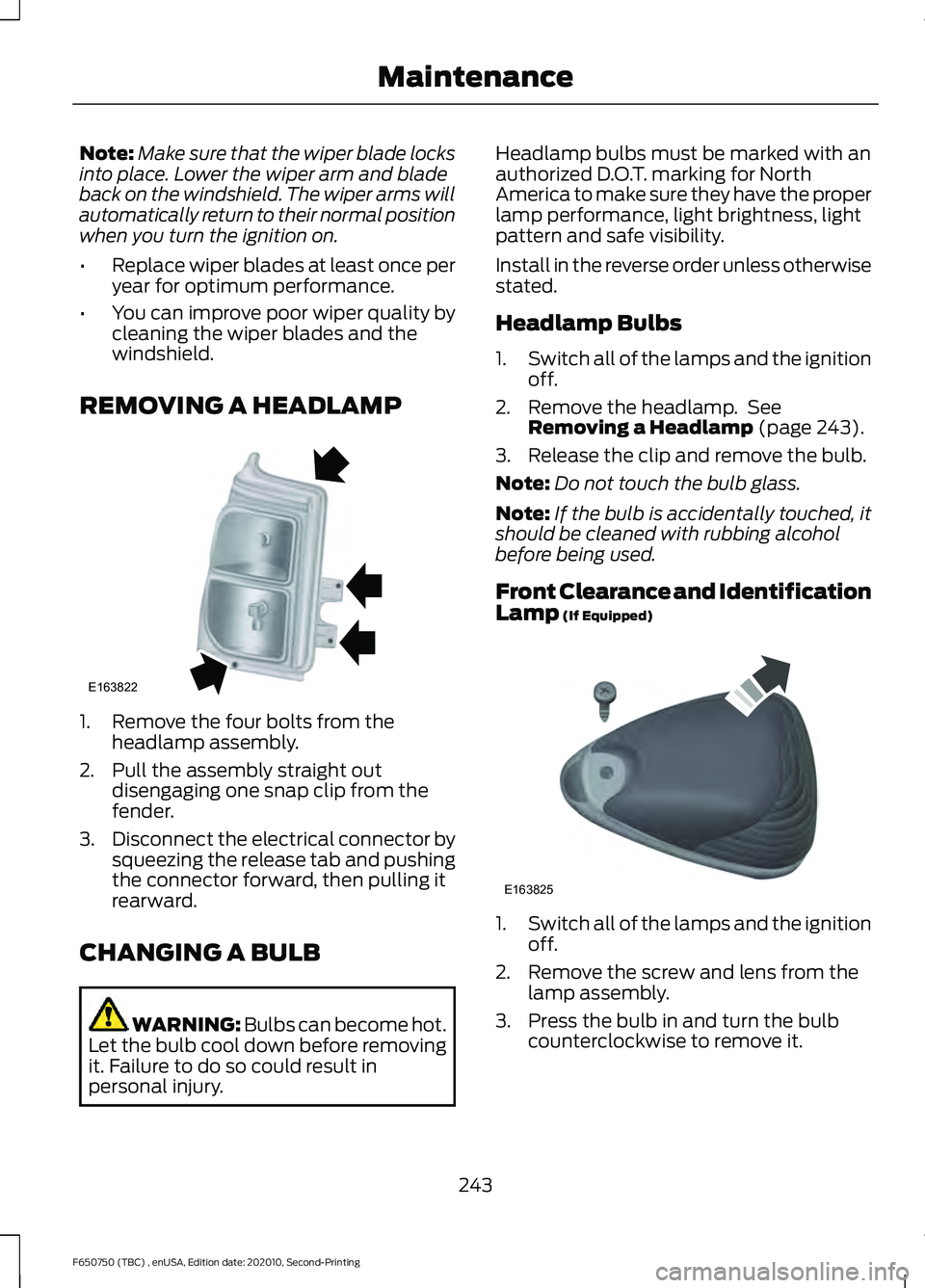
REMOVING A HEADLAMP 1. Remove the four bolts from the
headlamp assembly.
2. Pull the assembly straight out disengaging one snap clip from the
fender.
3. Disconnect the electrical connector by
squeezing the release tab and pushing
the connector forward, then pulling it
rearward.
CHANGING A BULB WARNING: Bulbs can become hot.
Let the bulb cool down before removing
it. Failure to do so could result in
personal injury. Headlamp bulbs must be marked with an
authorized D.O.T. marking for North
America to make sure they have the proper
lamp performance, light brightness, light
pattern and safe visibility.
Install in the reverse order unless otherwise
stated.
Headlamp Bulbs
1.
Switch all of the lamps and the ignition
off.
2. Remove the headlamp. See Removing a Headlamp (page 243).
3. Release the clip and remove the bulb.
Note: Do not touch the bulb glass.
Note: If the bulb is accidentally touched, it
should be cleaned with rubbing alcohol
before being used.
Front Clearance and Identification
Lamp
(If Equipped) 1.
Switch all of the lamps and the ignition
off.
2. Remove the screw and lens from the lamp assembly.
3. Press the bulb in and turn the bulb counterclockwise to remove it.
243
F650750 (TBC) , enUSA, Edition date: 202010, Second-Printing MaintenanceE163822 E163825