2021 FORD F650/750 Transmission
[x] Cancel search: TransmissionPage 208 of 390

Engine starting (with parking brake applied)
Check the gauge (diesel engine) or indicator light (gasoline
engine) to verify the alternator is charging.
Voltmeter
Inspect for excessive free play in the steering linkages. The
steering wheel should have less than 2 in (5 cm) of free play
at its rim.
Steering linkage free play
Verify the parking brake holds the vehicle by gently trying to
pull forward with the parking brake applied.
Parking brake
Verify operation using the following procedure. Chock the
wheels, if necessary. Push in the parking brake and, on
tractors, push in the tractor parking brake knob:
Air brakes
1. Verify the air compressor or governor cutout pressure is
approximately 120 psi (827 kPa).
2. Turn off the engine, and then turn the key back to the on
position (without starting the engine).
3. Without the brake pedal applied, note the air pressure drop
for one minute. It should be less than 2 psi (14 kPa) for single
vehicles and
3 psi (21 kPa) for combination vehicles.
4. Press and hold the brake pedal with
90 psi (621 kPa) or
more. Make sure there is no more than a 3 psi (21 kPa) per
minute leak for single vehicles and a 4 psi (28 kPa) minute
leak for combination vehicles.
5. Pump the brake pedal to deplete the system of air pressure.
The warning light and tone should turn on at 57 psi (393 kPa).
6. Pump the brake pedal and make sure the parking brake
and trailer parking brake knobs pop out at
20 psi (138 kPa)
or higher.
Verify that the fluid level is in the proper operating range. See
Automatic Transmission Fluid Check
(page 236).
Automatic transmission
fluid Front of vehicle
Verify all exterior lights illuminate and are clean.
Lights
Check headlights function on high and low beam.
Verify reflectors are clean, unbroken and of proper color (red
on rear, amber elsewhere).
205
F650750 (TBC) , enUSA, Edition date: 202010, Second-Printing Vehicle Inspection Guide
Page 213 of 390

Rear brakes
Inspect for cracked, worn or frayed hoses, and that all coup-
lings are secure.
Hoses
Verify that there are no cracks or dents, and that the cham-
bers are securely mounted.
Brake chambers
Inspect for broken, loose or missing parts.
Slack adjusters
Note: The angle between the push rod and adjuster arm
should be approximately 90 degrees when the brakes are
applied. When pulled by hand, the push rod should not move
more than approximately
1 in (2.5 cm).
Verify that there are no cracks, dents, holes, and no loose or
missing bolts and that the brake linings are not worn,
dangerously thin or contaminated by lubricant.
Drums Rear wheels
Check for even separation of dual wheels, and that the tires
are not touching each other.
Spacers
Inspect for damaged or bent rims. They should not have
welding repairs, and there should be no rust trails, which
indicate it is loose on the wheel.
Rims
Verify all lug nuts are present and not loose (look for rust
trails around the lug nuts). There should be no cracks radiating
from the lug bolt holes or distortion of the bolt holes.
Lug nuts
Trailer
If you are pulling a trailer, perform an
inspection of the trailer similar to that of
the tractor. The inspection should follow
trailer manufacturer recommendations
and should include at a minimum: general
condition, landing gear, doors, sides, lights,
reflectors, suspension, brakes, tires,
wheels, cargo placement, stability and
tie-downs. Transmission WARNING:
If the unit starts in gear
and/or the neutral start switch is not
functioning correctly, the vehicle may
inadvertently move which could result
in property damage, personal injury or
death.
Regularly inspect the transmission's
neutral start switch. The engine should
only start in neutral (N) or park (P) (if
equipped with a park position).
210
F650750 (TBC) , enUSA, Edition date: 202010, Second-Printing Vehicle Inspection Guide
Page 214 of 390
Inspect the transmission fluid level and
shift linkage for proper operation.
211
F650750 (TBC) , enUSA, Edition date: 202010, Second-Printing Vehicle Inspection Guide
Page 218 of 390
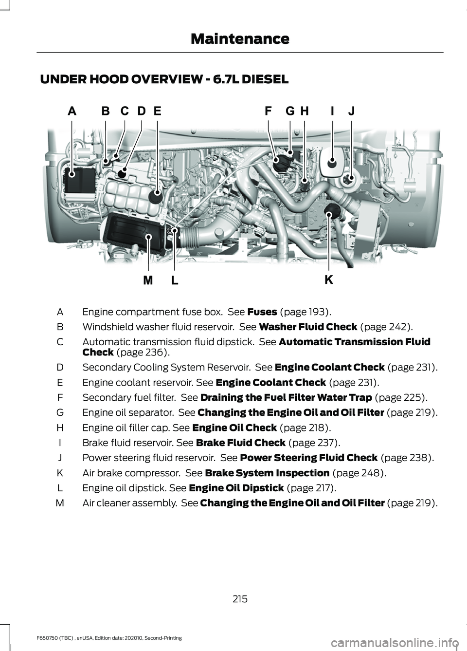
UNDER HOOD OVERVIEW - 6.7L DIESEL
Engine compartment fuse box. See Fuses (page 193).
A
Windshield washer fluid reservoir. See
Washer Fluid Check (page 242).
B
Automatic transmission fluid dipstick. See
Automatic Transmission Fluid
Check (page 236).
C
Secondary Cooling System Reservoir. See Engine Coolant Check (page 231).
D
Engine coolant reservoir.
See Engine Coolant Check (page 231).
E
Secondary fuel filter. See
Draining the Fuel Filter Water Trap (page 225).
F
Engine oil separator. See Changing the Engine Oil and Oil Filter (page 219).
G
Engine oil filler cap.
See Engine Oil Check (page 218).
H
Brake fluid reservoir.
See Brake Fluid Check (page 237).
I
Power steering fluid reservoir. See
Power Steering Fluid Check (page 238).
J
Air brake compressor. See
Brake System Inspection (page 248).
K
Engine oil dipstick.
See Engine Oil Dipstick (page 217).
L
Air cleaner assembly. See Changing the Engine Oil and Oil Filter (page 219).
M
215
F650750 (TBC) , enUSA, Edition date: 202010, Second-Printing MaintenanceE313700
Page 219 of 390
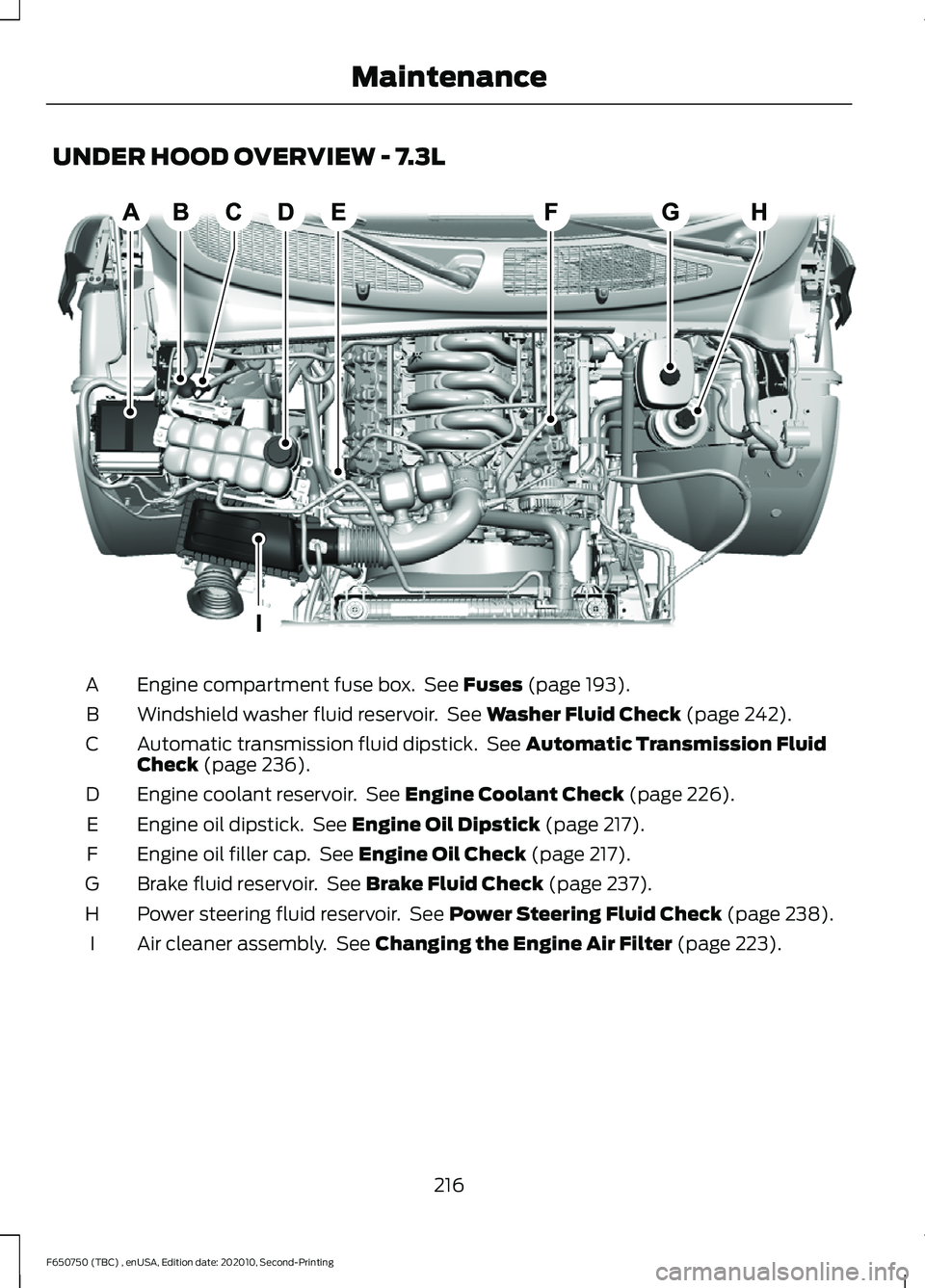
UNDER HOOD OVERVIEW - 7.3L
Engine compartment fuse box. See Fuses (page 193).
A
Windshield washer fluid reservoir. See
Washer Fluid Check (page 242).
B
Automatic transmission fluid dipstick. See
Automatic Transmission Fluid
Check (page 236).
C
Engine coolant reservoir. See
Engine Coolant Check (page 226).
D
Engine oil dipstick. See
Engine Oil Dipstick (page 217).
E
Engine oil filler cap. See
Engine Oil Check (page 217).
F
Brake fluid reservoir. See
Brake Fluid Check (page 237).
G
Power steering fluid reservoir. See
Power Steering Fluid Check (page 238).
H
Air cleaner assembly. See
Changing the Engine Air Filter (page 223).
I
216
F650750 (TBC) , enUSA, Edition date: 202010, Second-Printing MaintenanceE314523
Page 220 of 390
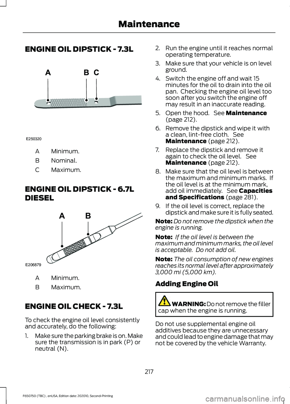
ENGINE OIL DIPSTICK - 7.3L
Minimum.
A
Nominal.
B
Maximum.
C
ENGINE OIL DIPSTICK - 6.7L
DIESEL Minimum.
A
Maximum.
B
ENGINE OIL CHECK - 7.3L
To check the engine oil level consistently
and accurately, do the following:
1. Make sure the parking brake is on. Make
sure the transmission is in park (P) or
neutral (N). 2. Run the engine until it reaches normal
operating temperature.
3. Make sure that your vehicle is on level ground.
4. Switch the engine off and wait 15 minutes for the oil to drain into the oil
pan. Checking the engine oil level too
soon after you switch the engine off
may result in an inaccurate reading.
5. Open the hood. See Maintenance
(page 212).
6. Remove the dipstick and wipe it with a clean, lint-free cloth. See
Maintenance
(page 212).
7. Replace the dipstick and remove it again to check the oil level. See
Maintenance
(page 212).
8. Make sure that the oil level is between
the maximum and minimum marks. If
the oil level is at the minimum mark,
add oil immediately. See
Capacities
and Specifications (page 281).
9. If the oil level is correct, replace the dipstick and make sure it is fully seated.
Note: Do not remove the dipstick when the
engine is running.
Note: If the oil level is between the
maximum and minimum marks, the oil level
is acceptable. Do not add oil.
Note: The oil consumption of new engines
reaches its normal level after approximately
3,000 mi (5,000 km)
.
Adding Engine Oil WARNING: Do not remove the filler
cap when the engine is running.
Do not use supplemental engine oil
additives because they are unnecessary
and could lead to engine damage that may
not be covered by the vehicle Warranty.
217
F650750 (TBC) , enUSA, Edition date: 202010, Second-Printing MaintenanceE250320 E206879
AB
Page 221 of 390
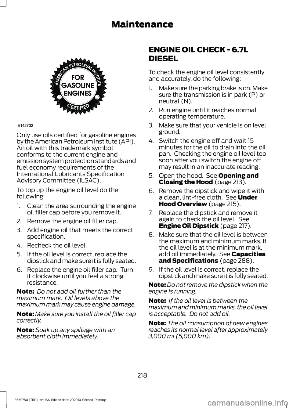
Only use oils certified for gasoline engines
by the American Petroleum Institute (API).
An oil with this trademark symbol
conforms to the current engine and
emission system protection standards and
fuel economy requirements of the
International Lubricants Specification
Advisory Committee (ILSAC).
To top up the engine oil level do the
following:
1. Clean the area surrounding the engine
oil filler cap before you remove it.
2. Remove the engine oil filler cap.
3. Add engine oil that meets the correct specification.
4. Recheck the oil level.
5. If the oil level is correct, replace the dipstick and make sure it is fully seated.
6. Replace the engine oil filler cap. Turn it clockwise until you feel a strong
resistance.
Note: Do not add oil further than the
maximum mark. Oil levels above the
maximum mark may cause engine damage.
Note: Make sure you install the oil filler cap
correctly.
Note: Soak up any spillage with an
absorbent cloth immediately. ENGINE OIL CHECK - 6.7L
DIESEL
To check the engine oil level consistently
and accurately, do the following:
1.
Make sure the parking brake is on. Make
sure the transmission is in park (P) or
neutral (N).
2. Run engine until it reaches normal operating temperature.
3. Make sure that your vehicle is on level ground.
4. Switch the engine off and wait 15 minutes for the oil to drain into the oil
pan. Checking the engine oil level too
soon after you switch the engine off
may result in an inaccurate reading.
5. Open the hood. See Opening and
Closing the Hood (page 213).
6. Remove the dipstick and wipe it with a clean, lint-free cloth. See
Under
Hood Overview (page 215).
7. Replace the dipstick and remove it again to check the oil level. See
Engine Oil Dipstick
(page 217).
8. Make sure that the oil level is between
the maximum and minimum marks. If
the oil level is at the minimum mark,
add oil immediately. See
Capacities
and Specifications (page 288).
9. If the oil level is correct, replace the dipstick and make sure it is fully seated.
Note: Do not remove the dipstick when the
engine is running.
Note: If the oil level is between the
maximum and minimum marks, the oil level
is acceptable. Do not add oil.
Note: The oil consumption of new engines
reaches its normal level after approximately
3,000 mi (5,000 km)
.
218
F650750 (TBC) , enUSA, Edition date: 202010, Second-Printing MaintenanceE142732
Page 228 of 390
5. Remove the clips that secure the air
filter housing cover. Push the air filter
cover toward the center of the vehicle
and up slightly to release it.
6. Remove the air filter element from the
air filter housing.
7. Install the new air filter element.
8. Engage the clips to secure the air filter housing cover to the air filter housing.
Be careful not to crimp the filter
element edges between the air filter
housing and cover. Ensure that you
align the tabs on the edge properly into
the slots.
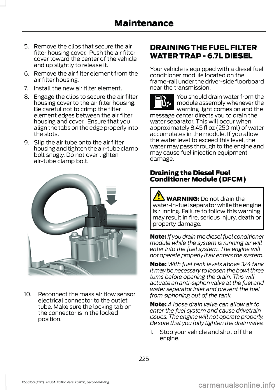
9. Slip the air tube onto the air filter housing and tighten the air-tube clamp
bolt snugly. Do not over tighten
air-tube clamp bolt. 10. Reconnect the mass air flow sensor
electrical connector to the outlet
tube. Make sure the locking tab on
the connector is in the locked
position. DRAINING THE FUEL FILTER
WATER TRAP - 6.7L DIESEL
Your vehicle is equipped with a diesel fuel
conditioner module located on the
frame-rail under the driver-side floorboard
near the transmission. You should drain water from the
module assembly whenever the
warning light comes on and the
message center directs you to drain the
water separator. This will occur when
approximately 8.45 fl oz (250 ml) of water
accumulates in the module. If you allow
the water level to exceed this level, the
water may pass through to the engine and
may cause fuel injection equipment
damage.
Draining the Diesel Fuel
Conditioner Module (DFCM) WARNING: Do not drain the
water-in-fuel separator while the engine
is running. Failure to follow this warning
may result in fire, serious injury, death or
property damage.
Note: If you drain the diesel fuel conditioner
module while the system is running air will
enter into the fuel system. The engine will
not operate properly if air enters the system.
Note: With fuel tank levels above 3⁄4 tank
it may be necessary to loosen the bowl three
turns before opening the drain. This will
actuate an anti-siphon valve at the fuel and
water separator inlet and prevent the fuel
from siphoning out of the tank.
Note: A loose drain valve can allow air to
enter the fuel system and cause drivetrain
issues. The engine will not operate properly.
Be sure that you fully tighten the drain valve.
1. Stop your vehicle and shut off the engine.
225
F650750 (TBC) , enUSA, Edition date: 202010, Second-Printing MaintenanceE317619