2021 FORD EXPLORER headlamp
[x] Cancel search: headlampPage 196 of 577

2.
Press the button on the left side of the
instrument panel next to the headlamp
switch to open the fuel filler door. The
fuel filler door can take up to 15
seconds to open before you can insert
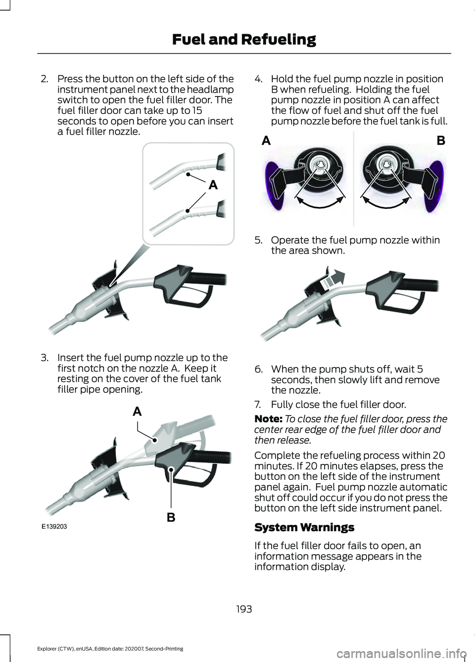
a fuel filler nozzle. 3. Insert the fuel pump nozzle up to the
first notch on the nozzle A. Keep it
resting on the cover of the fuel tank
filler pipe opening. 4. Hold the fuel pump nozzle in position
B when refueling. Holding the fuel
pump nozzle in position A can affect
the flow of fuel and shut off the fuel
pump nozzle before the fuel tank is full. 5. Operate the fuel pump nozzle within
the area shown. 6. When the pump shuts off, wait 5
seconds, then slowly lift and remove
the nozzle.
7. Fully close the fuel filler door.
Note: To close the fuel filler door, press the
center rear edge of the fuel filler door and
then release.
Complete the refueling process within 20
minutes. If 20 minutes elapses, press the
button on the left side of the instrument
panel again. Fuel pump nozzle automatic
shut off could occur if you do not press the
button on the left side instrument panel.
System Warnings
If the fuel filler door fails to open, an
information message appears in the
information display.
193
Explorer (CTW), enUSA, Edition date: 202007, Second-Printing Fuel and RefuelingE139202 E139203
A
B E206912 E119081
Page 266 of 577

•
Your vehicle is under the activation
speed.
• The direction indicator is active.
• Your vehicle is in a dynamic maneuver.
• The road has no or poor lane markings
in the camera field-of-view.
• The camera is obscured or unable to
detect the lane markings due to
environmental, traffic or vehicle
conditions. For example, significant sun
angles, shadows, snow, heavy rain or
fog, following a large vehicle that is
blocking or shadowing the lane or poor
headlamp illumination.
See Troubleshooting for additional
information.
White: Indicates that the system is
available or ready to provide a warning or
intervention on the indicated side. Note:
If your vehicle has lane centering
assist and the system is active, the walls
appear green instead of white.
Yellow: Indicates that the system is
providing or has just provided a lane
keeping aid intervention.
Red: Indicates that the system is providing
or has just provided a lane keeping alert
warning.
The system can be temporarily suppressed
at any time by the following:
• Quick braking.
• Fast acceleration.
• Using the direction indicator.
• Evasive steering maneuver.
• Driving too close to the lane markings.
Troubleshooting Why is the feature not available (line markings are gray) when I can see the lane markings
on the road?
Your vehicle speed is outside the operational range of the feature.
The sun is shining directly into the camera lens.
A quick intentional lane change has occurred.
Your vehicle stays too close to the lane markings.
Driving at high speeds in curves.
The last alert warning or aid intervention occurred a short time ago.
Ambiguous lane markings, for example in construction zones.
Rapid transition from light to dark, or from dark to light.
Sudden offset in lane markings.
ABS or AdvanceTrac ™ is active.
There is a camera blockage due to dirt, grime, fog, frost or water on the windshield.
You are driving too close to the vehicle in front of you.
263
Explorer (CTW), enUSA, Edition date: 202007, Second-Printing Driving Aids
Page 275 of 577

Note:
If your vehicle has a suspension kit
not approved by us, the system may not
correctly function.
Note: Always replace headlamp bulbs with
those specifically designed for your vehicle.
Other bulbs could reduce system
performance.
The system turns on when you switch the
ignition on and you cannot switch the
system off.
Using Speed Sign Recognition
Setting the System Speed Warning
You can set the system speed warning to
alert you when the vehicle speed exceeds
the speed limit recognized by the system
by a certain speed tolerance.
Note: The system remembers the last
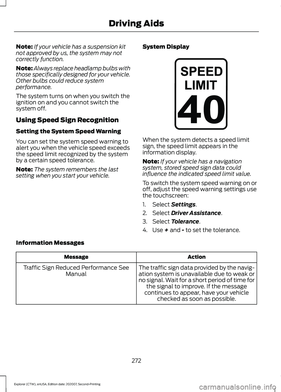
setting when you start your vehicle. System Display When the system detects a speed limit
sign, the speed limit appears in the
information display.
Note:
If your vehicle has a navigation
system, stored speed sign data could
influence the indicated speed limit value.
To switch the system speed warning on or
off, adjust the speed warning settings use
the touchscreen:
1. Select Settings.
2. Select
Driver Assistance.
3. Select
Tolerance.
4. Use
+ and - to set the tolerance.
Information Messages Action
Message
The traffic sign data provided by the navig-ation system is unavailable due to weak or
no signal. Wait for a short period of time for the signal to improve. If the message
continues to appear, have your vehicle checked as soon as possible.
Traffic Sign Reduced Performance See
Manual
272
Explorer (CTW), enUSA, Edition date: 202007, Second-Printing Driving AidsE317824
Page 317 of 577

Protected Component
Fuse Rating
Fuse or Relay
Number
Windshield and rear window washer pump
relay power.
15A
16
Charge status indicator (hybrid electric
vehicle).
5A
17
Starter motor.
30A
18
Headlamp leveling motors.
10A
21
Adaptive headlamps.
Electric power assisted steering module.
10A
22
Anti-lock brake system module with
integrated park brake.
10A
23
Powertrain control module.
10A
24
Hybrid powertrain control module.
Air quality sensor.
10A
25
360 camera with park aid.
Rear view camera.
Blind spot information system.
Adaptive cruise control module.
Transmission control module.
15A
26
Anti-lock brake system valves with integ-
rated park brake.
40A
28
Anti-lock brake system pump with integ-
rated park brake.
60A
29
Driver seat module.
30A
30
Passenger seat motor.
30A
31
Front media bin power point.
20A
32
Rear cargo area power point.
20A
33
Console end cap power point.
20A
34
Power point 4.
20A
35
Power inverter.
40A
36
Climate controlled seat module.
30A
38
Power liftgate module.
30A
41
314
Explorer (CTW), enUSA, Edition date: 202007, Second-Printing Fuses
Page 318 of 577

Protected Component
Fuse Rating
Fuse or Relay
Number
Trailer brake control module.
30A
42
Body control module.
60A
43
Brake on and off switch.
10A
44
Battery charger control module (hybrid
electric vehicle).
15A
46
Heated backlite.
40A
50
Heated steering wheel.
20A
54
Trailer tow park lamps.
20A
55
Trailer tow battery charge.
30A
57
Trailer tow backup lamps.
10A
58
Multi-contour seat module.
15A
61
Headlamp washer pump.
15A
62
Four-wheel drive module.
40A
64
Front window wiper motor.
30A
69
Rear window wiper motor.
15A
71
Not used (spare).
20A
72
Driver door module.
30A
73
Left-hand heated windshield.
50A
78
Right-hand heated windshield.
50A
79
Trailer tow.
20A
80
Not used (spare).
20A
82
Rear blower motor.
20A
88
Trailer tow lighting module.
20A
91
Integrated spark control (hybrid electric
vehicle).
15A
95
Not used (spare).
15A
96
Electric AC (hybrid electric vehicle).
10A
97
315
Explorer (CTW), enUSA, Edition date: 202007, Second-Printing Fuses
Page 320 of 577

Protected Component
Fuse Rating
Fuse or Relay
Number
USB smart charger 2.
5A
139
Traffic cam.
5A
142
Battery electronic control module.
15A
146
Left-hand headlamp module.
30A
148
Right-hand headlamp module.
30A
149
Not used (spare).
40A
150
Transmission control module (hybrid
electric vehicle).
25A
155
DC/DC converter (hybrid electric vehicle).
15A
159
Not used (spare).
10A
160
Low voltage service disconnect.
20A
168
Coolant pump (hybrid electric vehicle).
10A
169
Traction battery coolant pump (hybrid
electric vehicle).
10A
170
Pedestrian sounder (hybrid electric
vehicle).
Not used (spare).
10A
177
Note: Spare fuse amperage may vary.
Passenger Compartment Fuse
Panel
The fuse panel is under the instrument
panel to the left of the steering column. Note:
It may be easier to access the fuse
panel if you remove the finish trim piece.
317
Explorer (CTW), enUSA, Edition date: 202007, Second-Printing Fuses
Page 322 of 577

Protected Component
Fuse Rating
Fuse or Relay
Number
Rear climate control.
Not used.
—
10
Not used.
—
11
Climate control head.
7.5A
12
Gear shift module.
Steering column control module.
7.5A
13
Smart datalink connector.
Instrument cluster.
Not used (spare).
15A
14
SYNC.
15A
15
Integrated control panel.
Not used.
—
16
Headlamp control module.
7.5A
17
Not used (spare).
7.5A
18
Headlamp switch.
5A
19
Push button ignition switch.
Ignition switch.
5A
20
Telematics control unit module.
Key inhibit solenoid lock.
Not used.
5A
21
Not used (spare).
5A
22
Not used (spare).
30A
23
Moonroof.
30A
24
Not used (spare).
20A
25
Not used (spare).
30A
26
Not used (spare).
30A
27
Not used (spare).
30A
28
Not used (spare).
15A
29
Trailer brake connector.
5A
30
319
Explorer (CTW), enUSA, Edition date: 202007, Second-Printing Fuses
Page 341 of 577

After battery replacement, or in some
cases after charging the battery with an
external charger, the battery management
system requires eight hours of vehicle sleep
time to relearn the battery state of charge.
During this time your vehicle must remain
fully locked with the ignition switched off.
Note:
Prior to relearning the battery state
of charge, the battery management system
may temporarily disable some electrical
systems.
Electrical Accessory Installation
To make sure the battery management
system works correctly, do not connect an
electrical device ground connection
directly to the battery negative post. This
can cause inaccurate measurements of
the battery condition and potential
incorrect system operation.
Note: If you add electrical accessories or
components to the vehicle, it may adversely
affect battery performance and durability.
This may also affect the performance of
other electrical systems in the vehicle.
Remove and Reinstall the Battery
To disconnect or remove the battery, do
the following:
1. Apply the parking brake and switch the
ignition off.
2. Switch all electrical equipment off, for
example lights and radio.
3. Wait a minimum of two minutes before
disconnecting the battery.
Note: The engine management system has
a power hold function and remains powered
for a period of time after you switch the
ignition off. This is to allow diagnostic and
adaptive tables to be stored. Disconnecting
the battery without waiting can cause
damage not covered by the vehicle
Warranty. 4. Disconnect the negative battery cable
terminal.
5. Disconnect the positive battery cable terminal.
6. Remove the battery securing clamp.
7. Remove the battery.
8. To install, reverse the removal procedure.
Note: Before reconnecting the battery,
make sure the ignition remains switched off.
Note: Make sure the battery cable terminals
are fully tightened.
If you disconnect or replace the vehicle
battery, you must reset the following
features:
• Window bounce-back. See Power
Windows (page 96).
• Clock Settings.
• Pre-set radio stations.
Battery Disposal Make sure that you dispose of
old batteries in an
environmentally friendly way.
Seek advice from your local authority
about recycling old batteries.
ADJUSTING THE HEADLAMPS
Vertical Aim Adjustment
If your vehicle has been involved in a crash,
have the aim of the headlamp beam
checked by an authorized dealer.
338
Explorer (CTW), enUSA, Edition date: 202007, Second-Printing MaintenanceE107998