2021 FORD EXPLORER ignition
[x] Cancel search: ignitionPage 341 of 577
After battery replacement, or in some
cases after charging the battery with an
external charger, the battery management
system requires eight hours of vehicle sleep
time to relearn the battery state of charge.
During this time your vehicle must remain
fully locked with the ignition switched off.
Note:
Prior to relearning the battery state
of charge, the battery management system
may temporarily disable some electrical
systems.
Electrical Accessory Installation
To make sure the battery management
system works correctly, do not connect an
electrical device ground connection
directly to the battery negative post. This
can cause inaccurate measurements of
the battery condition and potential
incorrect system operation.
Note: If you add electrical accessories or
components to the vehicle, it may adversely
affect battery performance and durability.
This may also affect the performance of
other electrical systems in the vehicle.
Remove and Reinstall the Battery
To disconnect or remove the battery, do
the following:
1. Apply the parking brake and switch the
ignition off.
2. Switch all electrical equipment off, for
example lights and radio.
3. Wait a minimum of two minutes before
disconnecting the battery.
Note: The engine management system has
a power hold function and remains powered
for a period of time after you switch the
ignition off. This is to allow diagnostic and
adaptive tables to be stored. Disconnecting
the battery without waiting can cause
damage not covered by the vehicle
Warranty. 4. Disconnect the negative battery cable
terminal.
5. Disconnect the positive battery cable terminal.
6. Remove the battery securing clamp.
7. Remove the battery.
8. To install, reverse the removal procedure.
Note: Before reconnecting the battery,
make sure the ignition remains switched off.
Note: Make sure the battery cable terminals
are fully tightened.
If you disconnect or replace the vehicle
battery, you must reset the following
features:
• Window bounce-back. See Power
Windows (page 96).
• Clock Settings.
• Pre-set radio stations.
Battery Disposal Make sure that you dispose of
old batteries in an
environmentally friendly way.
Seek advice from your local authority
about recycling old batteries.
ADJUSTING THE HEADLAMPS
Vertical Aim Adjustment
If your vehicle has been involved in a crash,
have the aim of the headlamp beam
checked by an authorized dealer.
338
Explorer (CTW), enUSA, Edition date: 202007, Second-Printing MaintenanceE107998
Page 344 of 577
Note:
Make sure that the wiper arm does
not spring back against the glass when the
wiper blade is not attached.
2. Slightly rotate the wiper blade.
3. Remove the wiper blade.
4. To install, reverse the removal procedure.
Note: Make sure that the wiper blade locks
into place.
CHANGING THE REAR WIPER
BLADES
You can improve poor wiper quality by
cleaning the wiper blades and the
windshield.
Replace the wiper blades at least annually
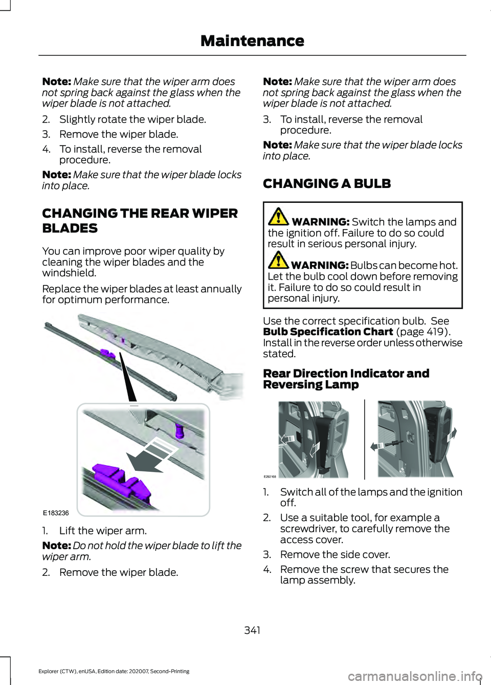
for optimum performance. 1. Lift the wiper arm.
Note:
Do not hold the wiper blade to lift the
wiper arm.
2. Remove the wiper blade. Note:
Make sure that the wiper arm does
not spring back against the glass when the
wiper blade is not attached.
3. To install, reverse the removal procedure.
Note: Make sure that the wiper blade locks
into place.
CHANGING A BULB WARNING: Switch the lamps and
the ignition off. Failure to do so could
result in serious personal injury. WARNING: Bulbs can become hot.
Let the bulb cool down before removing
it. Failure to do so could result in
personal injury.
Use the correct specification bulb. See
Bulb Specification Chart
(page 419).
Install in the reverse order unless otherwise
stated.
Rear Direction Indicator and
Reversing Lamp 1.
Switch all of the lamps and the ignition
off.
2. Use a suitable tool, for example a screwdriver, to carefully remove the
access cover.
3. Remove the side cover.
4. Remove the screw that secures the lamp assembly.
341
Explorer (CTW), enUSA, Edition date: 202007, Second-Printing MaintenanceE183236 E292168
Page 349 of 577

•
Never wash or rinse the engine while it
is hot or running; water in the running
engine may cause internal damage.
• Never wash or rinse any ignition coil,
spark plug wire or spark plug well, or
the area in and around these locations.
• Cover the battery, power distribution
box, and air filter assembly to prevent
water damage when cleaning the
engine.
CLEANING THE WINDOWS AND
WIPER BLADES
Car wash chemicals and environmental
fallout can result in windshield and wiper
blade contamination. Dirty windshield and
wipers will result in poor windshield wiper
operation. Keep the windshield and wiper
blades clean to maintain windshield wiper
performance.
To clean the windshield and wiper blades:
• Clean the windshield with a
non-abrasive glass cleaner. When
cleaning the interior of the windshield,
avoid getting any glass cleaner on the
instrument panel or door panels. Wipe
any glass cleaner off these surfaces
immediately.
• For windshields contaminated with
tree sap, chemicals, wax or bugs, clean
the entire windshield using steel wool
(no greater than 0000 grade) in a
circular motion and rinse with water.
• Clean the wiper blades with isopropyl
rubbing alcohol or windshield washer
concentrate.
Note: Do not use razor blades or other
sharp objects to clean or remove decals
from the inside of the heated rear window.
The vehicle warranty does not cover
damage caused to the heated rear window
grid lines. CLEANING THE INTERIOR WARNING: Do not use cleaning
solvents, bleach or dye on the vehicle's
seatbelts, as these actions may weaken
the belt webbing. WARNING:
On vehicles equipped
with seat-mounted airbags, do not use
chemical solvents or strong detergents.
Such products could contaminate the
side airbag system and affect
performance of the side airbag in a crash.
For fabric, carpets, cloth seats and seats
equipped with side airbags:
• Remove dust and loose dirt with a
vacuum cleaner.
• Remove light stains and soil with
Motorcraft Professional Strength
Carpet & Upholstery Cleaner.
• If grease or tar is present on the
material, spot-clean the area first with
Motorcraft Spot and Stain Remover. In
Canada, use Motorcraft Multi-Purpose
Cleaner.
• If a ring forms on the fabric after spot
cleaning, clean the entire area
immediately (but do not oversaturate)
or the ring will set.
• Do not use household cleaning
products or glass cleaners, which can
stain and discolor the fabric and affect
the flame retardant abilities of the seat
materials.
Mirrors
Do not clean the housing or glass of any
mirror with harsh abrasives, fuel or other
petroleum or ammonia-based cleaning
products.
346
Explorer (CTW), enUSA, Edition date: 202007, Second-Printing Vehicle Care
Page 376 of 577
•
To reduce the chances of interference
from another vehicle, perform the
system reset procedure at least 3 ft
(1 m) away from another Ford Motor
Company vehicle undergoing the
system reset procedure at the same
time.
• Do not wait more than two minutes
between resetting each tire sensor or
the system can time-out and you have
to repeat the entire procedure on all
four wheels.
• A double horn sounds indicating the
need to repeat the procedure.
Performing the System Reset Procedure
Read the entire procedure before
attempting.
1. Drive the vehicle above
20 mph
(32 km/h) for at least two minutes,
then park in a safe location where you
can easily get to all four tires and have
access to an air pump.
2. Place the ignition in the off position and
keep the key in the ignition.
3. Cycle the ignition to the on position with the engine off.
4. Turn the hazard flashers on then off three times. You must accomplish this
within 10 seconds. If you successfully
enter the reset mode, the horn sounds
once, the system indicator flashes and
a message shows in the information
display. If this does not occur, please
try again starting at step 2. If after
repeated attempts to enter the reset
mode, the horn does not sound, the
system indicator does not flash and no
message shows in the information
display, seek service from your
authorized dealer. 5. Train the tire pressure monitoring
system sensors in the tires using the
following system reset sequence
starting with the left front tire in the
following clockwise order: Left front -
driver side front tire, Right front -
passenger side front tire, Right rear -
passenger side rear tire, Left rear -
driver side rear tire.
6. Remove the valve cap from the valve stem on the left front tire. Decrease the
air pressure until the horn sounds.
Note: The single horn tone confirms that
the sensor identification code has been
learned by the module for this position. If a
double horn is heard, the reset procedure
was unsuccessful, and you must repeat it.
7. Remove the valve cap from the valve stem on the right front tire. Decrease
the air pressure until the horn sounds.
8. Remove the valve cap from the valve stem on the right rear tire. Decrease the
air pressure until the horn sounds.
9. Remove the valve cap from the valve stem on the left rear tire. Decrease the
air pressure until the horn sounds.
Training is complete after the horn
sounds for the last tire trained, driver
side rear tire, the system indicator
stops flashing, and a message shows
in the information display.
10. Turn the ignition off. If two short horn
beeps are heard, the reset procedure
was unsuccessful and you must
repeat it. If after repeating the
procedure and two short beeps are
heard when the ignition is turned to
off, seek assistance from your
authorized dealer.
373
Explorer (CTW), enUSA, Edition date: 202007, Second-Printing Wheels and Tires
Page 385 of 577
ENGINE SPECIFICATIONS - 2.3L ECOBOOST™
2.3L EcoBoost
Engine
138 in³ (2,261 cm³)
Displacement.
Minimum 87 octane
Fuel type.
1-3-4-2
Firing order.
Coil on plug
Ignition system.
0.028–0.031 in (0.7–0.8 mm)
Spark plug gap.
10:1
Compression ratio.
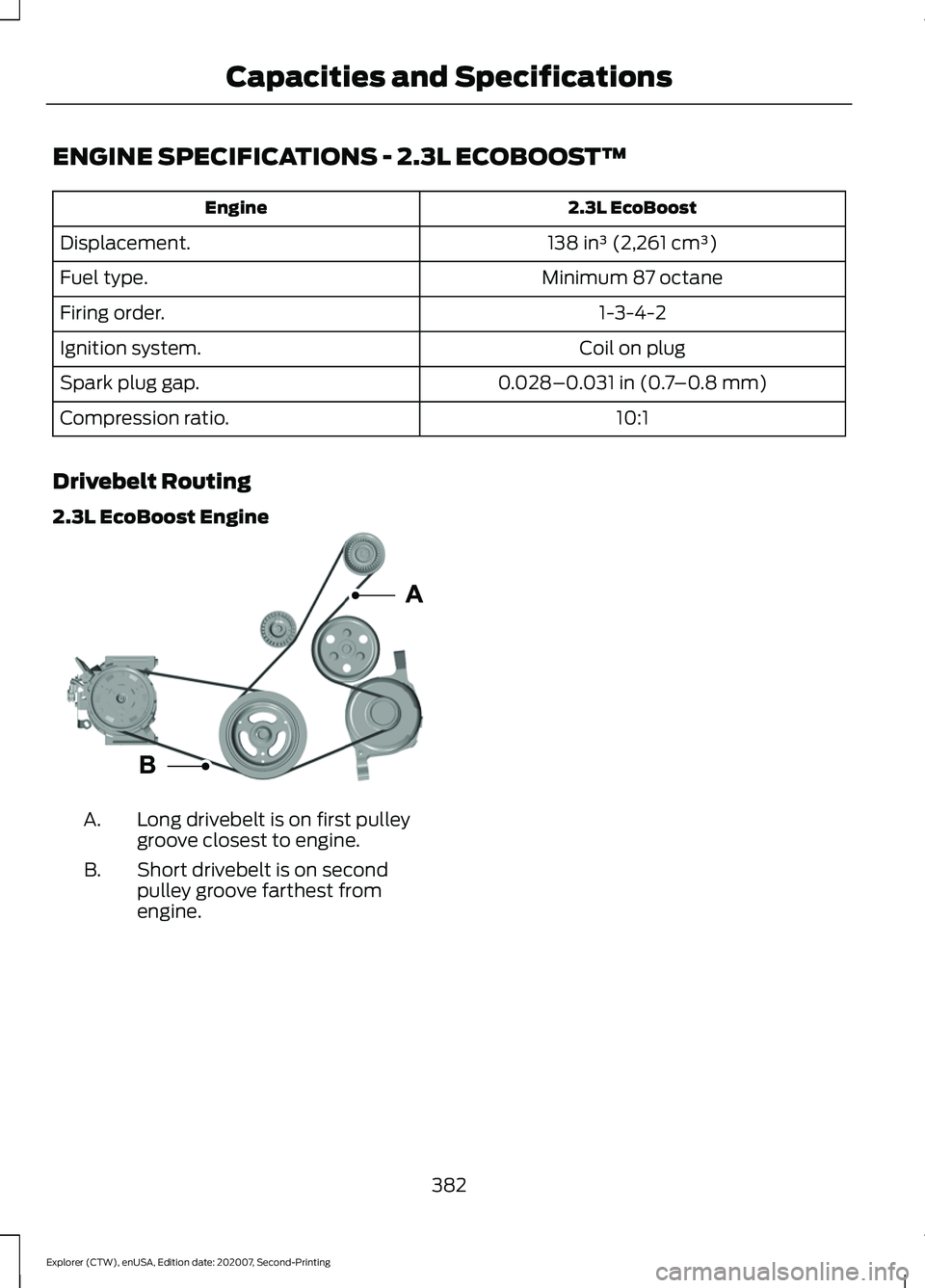
Drivebelt Routing
2.3L EcoBoost Engine Long drivebelt is on first pulley
groove closest to engine.
A.
Short drivebelt is on second
pulley groove farthest from
engine.
B.
382
Explorer (CTW), enUSA, Edition date: 202007, Second-Printing Capacities and SpecificationsE293908
Page 386 of 577
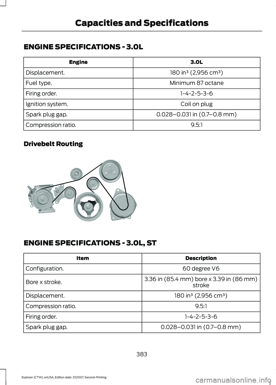
ENGINE SPECIFICATIONS - 3.0L
3.0L
Engine
180 in³ (2,956 cm³)
Displacement.
Minimum 87 octane
Fuel type.
1-4-2-5-3-6
Firing order.
Coil on plug
Ignition system.
0.028–0.031 in (0.7–0.8 mm)
Spark plug gap.
9.5:1
Compression ratio.
Drivebelt Routing ENGINE SPECIFICATIONS - 3.0L, ST
Description
Item
60 degree V6
Configuration.
3.36 in (85.4 mm) bore x 3.39 in (86 mm)
stroke
Bore x stroke.
180 in³ (2,956 cm³)
Displacement.
9.5:1
Compression ratio.
1-4-2-5-3-6
Firing order.
0.028–0.031 in (0.7–0.8 mm)
Spark plug gap.
383
Explorer (CTW), enUSA, Edition date: 202007, Second-Printing Capacities and SpecificationsE297178
Page 387 of 577
Description
Item
400 hp1
Horsepower.
415 lb.ft1
Torque.
6500 RPM
Redline.
Overhead cam - roller finger followers
Valvetrain.
Coil on plug
Ignition.
2.4 in (60 mm)
Throttle body.
Cast aluminum
Pistons.
Forged steel
Crankshaft.
Forged steel
Connecting rods.
Twin tubocharged
Induction.
18.0 psi (124 kPa)
Max Boost.
Dual 2.16 in (55 mm) exhaust with quad3 in (76 mm) chrome tips
Exhaust system.
1 When using premium fuel.
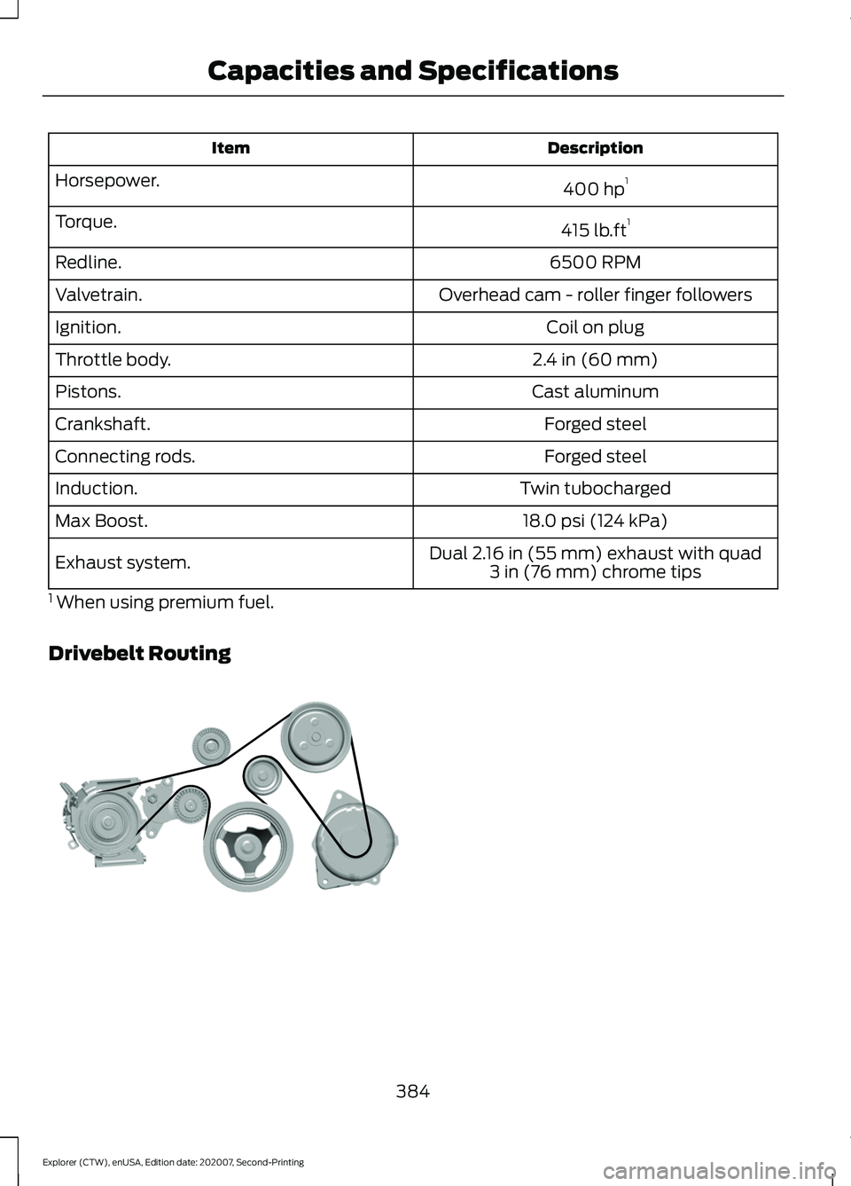
Drivebelt Routing 384
Explorer (CTW), enUSA, Edition date: 202007, Second-Printing Capacities and SpecificationsE297178
Page 388 of 577
ENGINE SPECIFICATIONS - 3.3L, GASOLINE
3.3L
Engine
204 in³ (3,340 cm³)
Displacement.
Minimum 87 octane
Fuel type.
1-4-2-5-3-6
Firing order.
Coil on plug
Ignition system.
0.049–0.053 in (1.25–1.35 mm)
Spark plug gap.
12.0:1
Compression ratio.
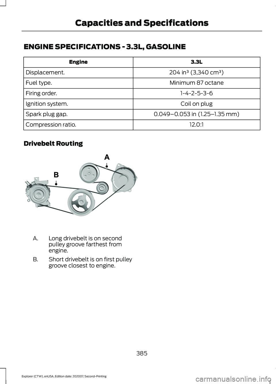
Drivebelt Routing Long drivebelt is on second
pulley groove farthest from
engine.
A.
Short drivebelt is on first pulley
groove closest to engine.
B.
385
Explorer (CTW), enUSA, Edition date: 202007, Second-Printing Capacities and SpecificationsE288323