2021 FORD EXPLORER light
[x] Cancel search: lightPage 299 of 577
![FORD EXPLORER 2021 Owners Manual •
Carry unnecessary weight
(approximately 1 mpg [0.4 km/L] is
lost for every 395 lb (180 kg) of weight
carried).
• Driving with the wheels out of
alignment.
Conditions
• Heavily loading a vehicl FORD EXPLORER 2021 Owners Manual •
Carry unnecessary weight
(approximately 1 mpg [0.4 km/L] is
lost for every 395 lb (180 kg) of weight
carried).
• Driving with the wheels out of
alignment.
Conditions
• Heavily loading a vehicl](/manual-img/11/40606/w960_40606-298.png)
•
Carry unnecessary weight
(approximately 1 mpg [0.4 km/L] is
lost for every 395 lb (180 kg) of weight
carried).
• Driving with the wheels out of
alignment.
Conditions
• Heavily loading a vehicle or towing a
trailer may reduce fuel economy at any
speed.
• Adding certain accessories to your
vehicle (for example bug deflectors,
rollbars, light bars, running boards, ski
racks or luggage racks) may reduce
fuel economy.
• To maximize the fuel economy, drive
with the tonneau cover installed (if
equipped).
• Using fuel blended with alcohol may
lower fuel economy.
• Fuel economy may decrease with lower
temperatures during the first
5–10 mi
(12 –16 km) of driving.
• Driving on flat terrain offers improved
fuel economy as compared to driving
on hilly terrain.
• Transmissions give their best fuel
economy when operated in the top
cruise gear and with steady pressure
on the gas pedal.
• Four-wheel-drive operation (if
equipped) is less fuel efficient than
two-wheel-drive operation.
• Close the windows for high-speed
driving.
COLD WEATHER
PRECAUTIONS
The functional operation of some
components and systems can be affected
at temperatures below approximately
-13°F (-25°C)
. BREAKING-IN
Tires
You need to break in new tires for
approximately
300 mi (480 km). During
this time, your vehicle may exhibit some
unusual driving characteristics.
Brakes and Clutch
Avoid heavy use of the brakes and clutch
if possible for the first
100 mi (160 km) in
town and for the first 1,000 mi (1,600 km)
on freeways.
DRIVING THROUGH WATER WARNING:
Do not drive through
flowing or deep water as you may lose
control of your vehicle.
Note: Driving through standing water can
cause vehicle damage.
Note: Engine damage can occur if water
enters the air filter.
Before driving through standing water,
check the depth. Never drive through water
that is higher than the bottom of the front
rocker area of your vehicle. 296
Explorer (CTW), enUSA, Edition date: 202007, Second-Printing Driving HintsE259345
Page 300 of 577
When driving through standing water, drive
very slowly and do not stop your vehicle.
Your brake performance and traction may
be limited. After driving through water and
as soon as it is safe to do so:
•
Lightly press the brake pedal to dry the
brakes and to check that they work.
• Check that the horn works.
• Check that the exterior lights work.
• Turn the steering wheel to check that
the steering power assist works.
FLOOR MATS WARNING: Use a floor mat
designed to fit the footwell of your
vehicle that does not obstruct the pedal
area. Failure to follow this instruction
could result in the loss of control of your
vehicle, personal injury or death. WARNING:
Pedals that cannot
move freely can cause loss of vehicle
control and increase the risk of serious
personal injury. WARNING:
Secure the floor mat
to both retention devices so that it
cannot slip out of position and interfere
with the pedals. Failure to follow this
instruction could result in the loss of
control of your vehicle, personal injury or
death. WARNING: Do not place additional
floor mats or any other covering on top
of the original floor mats. This could
result in the floor mat interfering with the
operation of the pedals. Failure to follow
this instruction could result in the loss of
control of your vehicle, personal injury or
death. WARNING:
Always make sure that
objects cannot fall into the driver foot
well while your vehicle is moving. Objects
that are loose can become trapped
under the pedals causing a loss of
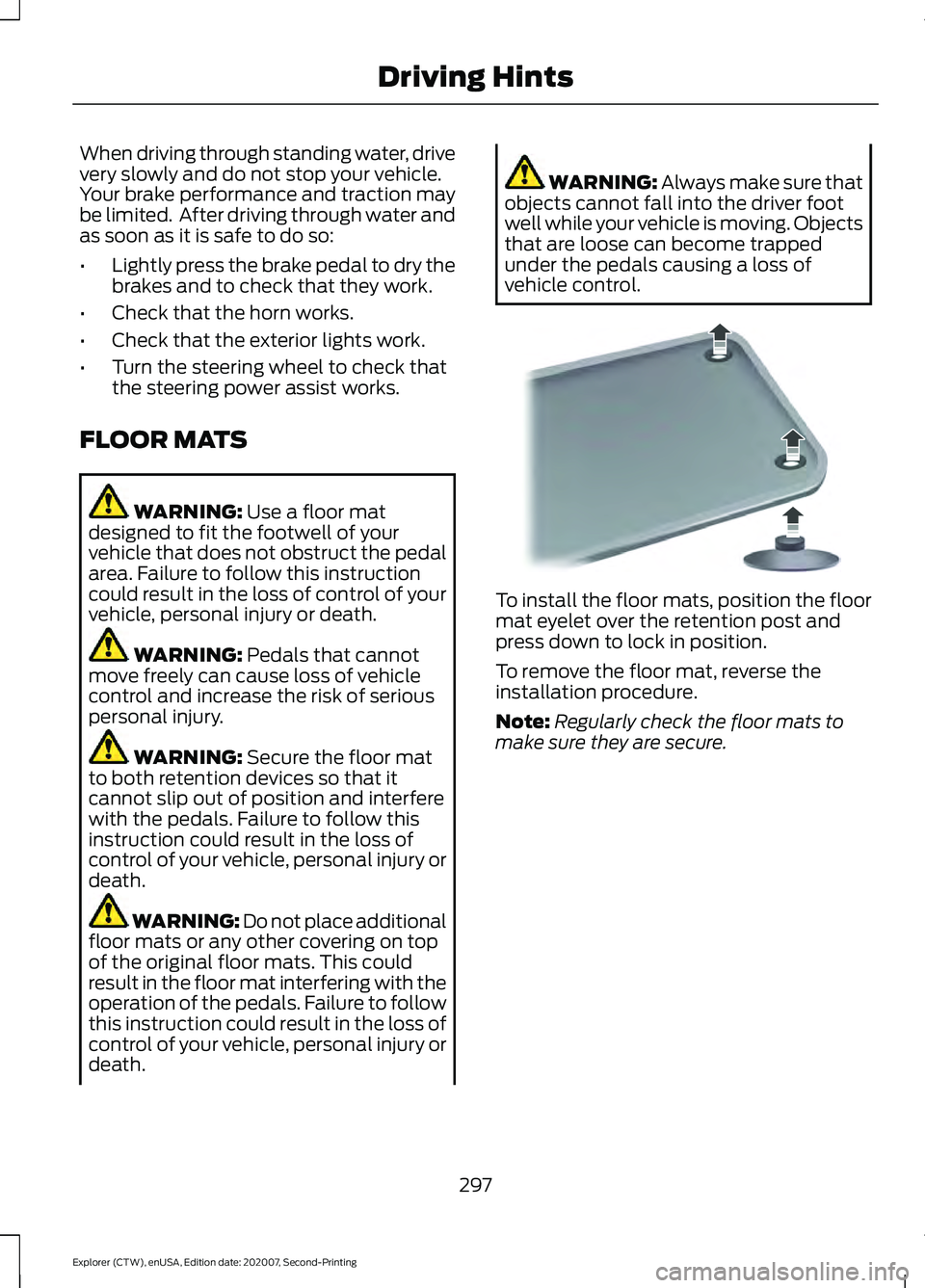
vehicle control. To install the floor mats, position the floor
mat eyelet over the retention post and
press down to lock in position.
To remove the floor mat, reverse the
installation procedure.
Note:
Regularly check the floor mats to
make sure they are secure.
297
Explorer (CTW), enUSA, Edition date: 202007, Second-Printing Driving HintsE142666
Page 303 of 577
4. You can attempt to start the vehicle
by pressing the brake pedal and
START/STOP, or press START/STOP
without pressing the brake pedal.
5. If the vehicle does not start, repeat steps 1 through 4.
JUMP STARTING THE VEHICLE WARNING:
Batteries normally
produce explosive gases which can
cause personal injury. Therefore, do not
allow flames, sparks or lighted
substances to come near the battery.
When working near the battery, always
shield your face and protect your eyes.
Always provide correct ventilation. WARNING:
Keep batteries out of
reach of children. Batteries contain
sulfuric acid. Avoid contact with skin,
eyes or clothing. Shield your eyes when
working near the battery to protect
against possible splashing of acid
solution. In case of acid contact with skin
or eyes, flush immediately with water for
a minimum of 15 minutes and get prompt
medical attention. If acid is swallowed,
call a physician immediately. WARNING:
Use only adequately
sized cables with insulated clamps.
Preparing Your Vehicle
Do not attempt to push-start your
automatic transmission vehicle.
Note: Attempting to push-start a vehicle
with an automatic transmission may cause
transmission damage.
Note: Use only a 12-volt supply to start your
vehicle. Note:
Do not disconnect the battery of the
disabled vehicle as this could damage the
vehicle electrical system.
Park the booster vehicle close to the hood
of the disabled vehicle, making sure the
two vehicles do not touch.
Locating the Jump Starting
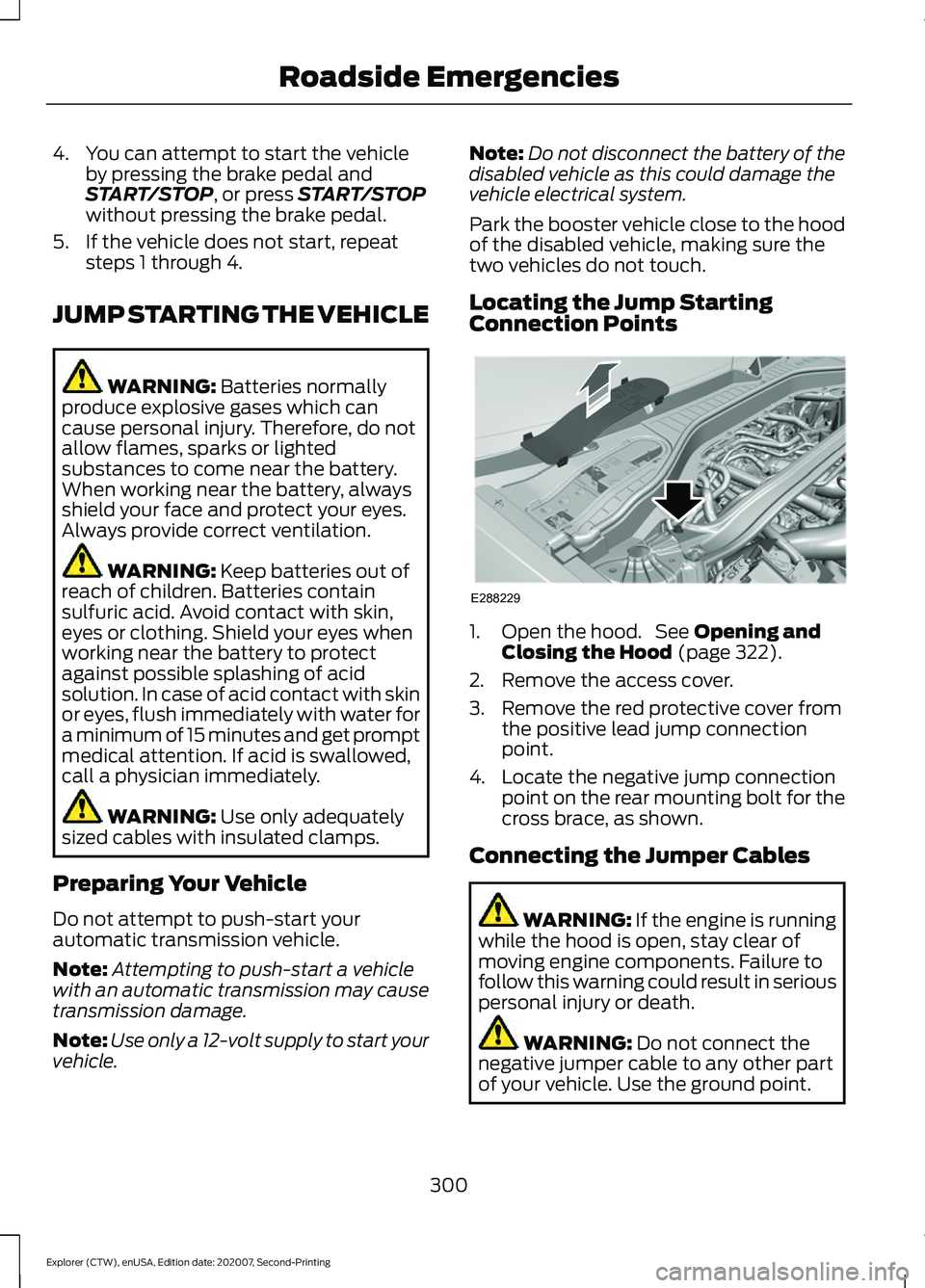
Connection Points 1. Open the hood. See
Opening and
Closing the Hood (page 322).
2. Remove the access cover.
3. Remove the red protective cover from the positive lead jump connection
point.
4. Locate the negative jump connection point on the rear mounting bolt for the
cross brace, as shown.
Connecting the Jumper Cables WARNING: If the engine is running
while the hood is open, stay clear of
moving engine components. Failure to
follow this warning could result in serious
personal injury or death. WARNING:
Do not connect the
negative jumper cable to any other part
of your vehicle. Use the ground point.
300
Explorer (CTW), enUSA, Edition date: 202007, Second-Printing Roadside EmergenciesE288229
Page 318 of 577

Protected Component
Fuse Rating
Fuse or Relay
Number
Trailer brake control module.
30A
42
Body control module.
60A
43
Brake on and off switch.
10A
44
Battery charger control module (hybrid
electric vehicle).
15A
46
Heated backlite.
40A
50
Heated steering wheel.
20A
54
Trailer tow park lamps.
20A
55
Trailer tow battery charge.
30A
57
Trailer tow backup lamps.
10A
58
Multi-contour seat module.
15A
61
Headlamp washer pump.
15A
62
Four-wheel drive module.
40A
64
Front window wiper motor.
30A
69
Rear window wiper motor.
15A
71
Not used (spare).
20A
72
Driver door module.
30A
73
Left-hand heated windshield.
50A
78
Right-hand heated windshield.
50A
79
Trailer tow.
20A
80
Not used (spare).
20A
82
Rear blower motor.
20A
88
Trailer tow lighting module.
20A
91
Integrated spark control (hybrid electric
vehicle).
15A
95
Not used (spare).
15A
96
Electric AC (hybrid electric vehicle).
10A
97
315
Explorer (CTW), enUSA, Edition date: 202007, Second-Printing Fuses
Page 334 of 577

8. Install the air filter housing cover.
9. Engage the clips to secure the air filter
housing cover to the air filter housing.
10. Reconnect the boot to the air filter housing cover and torque to 3.69 lb.ft
(5 Nm).
ENGINE COOLANT CHECK WARNING:
Do not remove the
coolant reservoir cap when the engine is
on or the cooling system is hot. Wait 10
minutes for the cooling system to cool
down. Cover the coolant reservoir cap
with a thick cloth to prevent the
possibility of scalding and slowly remove
the cap. Failure to follow this instruction
could result in personal injury. WARNING:
Do not put coolant in
the windshield washer reservoir. If
sprayed on the windshield, coolant could
make it difficult to see through the
windshield. WARNING:
To reduce the risk of
personal injury, make sure the engine is
cool before unscrewing the coolant
pressure relief cap. The cooling system
is under pressure. Steam and hot liquid
can come out forcefully when you loosen
the cap slightly. WARNING:
Do not add coolant
further than the MAX mark.
When the engine is cold, check the
concentration and level of the coolant at
the intervals listed in the scheduled
maintenance information. See Scheduled
Maintenance
(page 482).
Note: Make sure that the coolant level is
between the
MIN and the MAX marks on
the coolant reservoir. Note:
Coolant expands when it is hot. The
level may extend beyond the
MAX mark.
Maintain coolant concentration within
48% to 50%, which equates to a freeze
point between
-29°F (-34°C) and -35°F
(-37°C). Coolant concentration should be
checked using a refractometer. We do not
recommend the use of hydrometers or
coolant test strips for measuring coolant
concentration.
Adding Coolant WARNING:
Do not add engine
coolant when the engine is on or the
cooling system is hot. Failure to follow
this instruction could result in personal
injury. WARNING:
Do not remove the
coolant reservoir cap when the engine is
on or the cooling system is hot. Wait 10
minutes for the cooling system to cool
down. Cover the coolant reservoir cap
with a thick cloth to prevent the
possibility of scalding and slowly remove
the cap. Failure to follow this instruction
could result in personal injury. WARNING:
Do not put coolant in
the windshield washer reservoir. If
sprayed on the windshield, coolant could
make it difficult to see through the
windshield.
Note: Do not use stop leak pellets, cooling
system sealants, or non-specified additives
as they can cause damage to the engine
cooling or heating systems. Resulting
component damage may not be covered by
the vehicle Warranty.
Note: Automotive fluids are not
interchangeable.
331
Explorer (CTW), enUSA, Edition date: 202007, Second-Printing Maintenance
Page 339 of 577
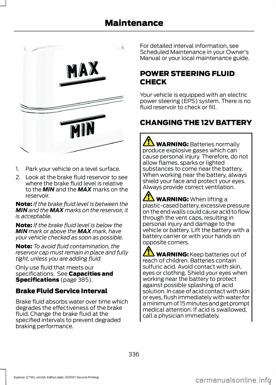
1. Park your vehicle on a level surface.
2. Look at the brake fluid reservoir to see
where the brake fluid level is relative
to the MIN and the MAX marks on the
reservoir.
Note: If the brake fluid level is between the
MIN
and the MAX marks on the reservoir, it
is acceptable.
Note: If the brake fluid level is below the
MIN
mark or above the MAX mark, have
your vehicle checked as soon as possible.
Note: To avoid fluid contamination, the
reservoir cap must remain in place and fully
tight, unless you are adding fluid.
Only use fluid that meets our
specifications. See
Capacities and
Specifications (page 385).
Brake Fluid Service Interval
Brake fluid absorbs water over time which
degrades the effectiveness of the brake
fluid. Change the brake fluid at the
specified intervals to prevent degraded
braking performance. For detailed interval information, see
Scheduled Maintenance in your Owner's
Manual or your local maintenance guide.
POWER STEERING FLUID
CHECK
Your vehicle is equipped with an electric
power steering (EPS) system. There is no
fluid reservoir to check or fill.
CHANGING THE 12V BATTERY
WARNING:
Batteries normally
produce explosive gases which can
cause personal injury. Therefore, do not
allow flames, sparks or lighted
substances to come near the battery.
When working near the battery, always
shield your face and protect your eyes.
Always provide correct ventilation. WARNING:
When lifting a
plastic-cased battery, excessive pressure
on the end walls could cause acid to flow
through the vent caps, resulting in
personal injury and damage to the
vehicle or battery. Lift the battery with a
battery carrier or with your hands on
opposite corners. WARNING:
Keep batteries out of
reach of children. Batteries contain
sulfuric acid. Avoid contact with skin,
eyes or clothing. Shield your eyes when
working near the battery to protect
against possible splashing of acid
solution. In case of acid contact with skin
or eyes, flush immediately with water for
a minimum of 15 minutes and get prompt
medical attention. If acid is swallowed,
call a physician immediately.
336
Explorer (CTW), enUSA, Edition date: 202007, Second-Printing MaintenanceE170684
Page 341 of 577
After battery replacement, or in some
cases after charging the battery with an
external charger, the battery management
system requires eight hours of vehicle sleep
time to relearn the battery state of charge.
During this time your vehicle must remain
fully locked with the ignition switched off.
Note:
Prior to relearning the battery state
of charge, the battery management system
may temporarily disable some electrical
systems.
Electrical Accessory Installation
To make sure the battery management
system works correctly, do not connect an
electrical device ground connection
directly to the battery negative post. This
can cause inaccurate measurements of
the battery condition and potential
incorrect system operation.
Note: If you add electrical accessories or
components to the vehicle, it may adversely
affect battery performance and durability.
This may also affect the performance of
other electrical systems in the vehicle.
Remove and Reinstall the Battery
To disconnect or remove the battery, do
the following:
1. Apply the parking brake and switch the
ignition off.
2. Switch all electrical equipment off, for
example lights and radio.
3. Wait a minimum of two minutes before
disconnecting the battery.
Note: The engine management system has
a power hold function and remains powered
for a period of time after you switch the
ignition off. This is to allow diagnostic and
adaptive tables to be stored. Disconnecting
the battery without waiting can cause
damage not covered by the vehicle
Warranty. 4. Disconnect the negative battery cable
terminal.
5. Disconnect the positive battery cable terminal.
6. Remove the battery securing clamp.
7. Remove the battery.
8. To install, reverse the removal procedure.
Note: Before reconnecting the battery,
make sure the ignition remains switched off.
Note: Make sure the battery cable terminals
are fully tightened.
If you disconnect or replace the vehicle
battery, you must reset the following
features:
• Window bounce-back. See Power
Windows (page 96).
• Clock Settings.
• Pre-set radio stations.
Battery Disposal Make sure that you dispose of
old batteries in an
environmentally friendly way.
Seek advice from your local authority
about recycling old batteries.
ADJUSTING THE HEADLAMPS
Vertical Aim Adjustment
If your vehicle has been involved in a crash,
have the aim of the headlamp beam
checked by an authorized dealer.
338
Explorer (CTW), enUSA, Edition date: 202007, Second-Printing MaintenanceE107998
Page 342 of 577
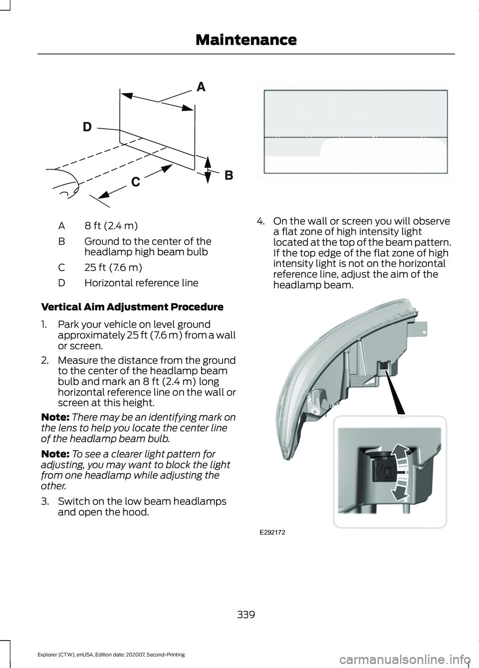
8 ft (2.4 m)
A
Ground to the center of the
headlamp high beam bulb
B
25 ft (7.6 m)
C
Horizontal reference line
D
Vertical Aim Adjustment Procedure
1. Park your vehicle on level ground approximately 25 ft (7.6 m) from a wall
or screen.
2. Measure the distance from the ground
to the center of the headlamp beam
bulb and mark an
8 ft (2.4 m) long
horizontal reference line on the wall or
screen at this height.
Note: There may be an identifying mark on
the lens to help you locate the center line
of the headlamp beam bulb.
Note: To see a clearer light pattern for
adjusting, you may want to block the light
from one headlamp while adjusting the
other.
3. Switch on the low beam headlamps and open the hood. 4. On the wall or screen you will observe
a flat zone of high intensity light
located at the top of the beam pattern.
If the top edge of the flat zone of high
intensity light is not on the horizontal
reference line, adjust the aim of the
headlamp beam. 339
Explorer (CTW), enUSA, Edition date: 202007, Second-Printing MaintenanceE142592 E142465 E292172