2021 FORD ESCAPE height
[x] Cancel search: heightPage 44 of 589

How Does Sensitive Locking Mode
Work
If the driver suddenly brakes, turns a corner
sharply, or the vehicle receives an impact
of about 5 mph (8 km/h) or more, the
seatbelts lock to help reduce forward
movement of the driver and passengers.
In addition, the seatbelt retractor locks if
you pull the seatbelt webbing out too
quickly. If the retractor locks, slowly lower
the height adjuster to allow the seatbelt
to retract.
If the retractor does not unlock, pull the
seatbelt out slowly then feed a small
length of webbing back toward the stowed
position.
AUTOMATIC LOCKING MODE
What Is Automatic Locking Mode
This is a safety feature built into the
seatbelt retractors that keeps the
seatbelts pre-locked.
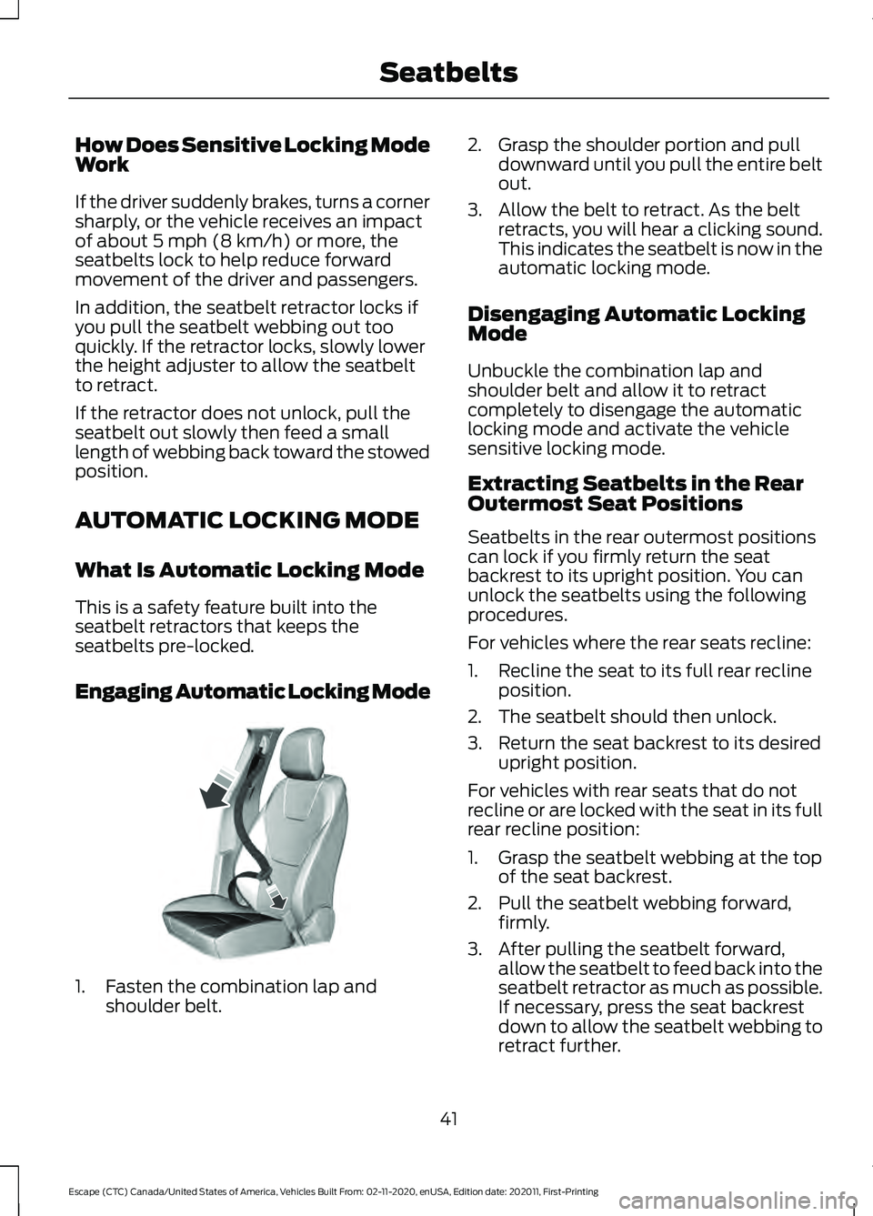
Engaging Automatic Locking Mode 1. Fasten the combination lap and
shoulder belt. 2. Grasp the shoulder portion and pull
downward until you pull the entire belt
out.
3. Allow the belt to retract. As the belt retracts, you will hear a clicking sound.
This indicates the seatbelt is now in the
automatic locking mode.
Disengaging Automatic Locking
Mode
Unbuckle the combination lap and
shoulder belt and allow it to retract
completely to disengage the automatic
locking mode and activate the vehicle
sensitive locking mode.
Extracting Seatbelts in the Rear
Outermost Seat Positions
Seatbelts in the rear outermost positions
can lock if you firmly return the seat
backrest to its upright position. You can
unlock the seatbelts using the following
procedures.
For vehicles where the rear seats recline:
1. Recline the seat to its full rear recline position.
2. The seatbelt should then unlock.
3. Return the seat backrest to its desired upright position.
For vehicles with rear seats that do not
recline or are locked with the seat in its full
rear recline position:
1. Grasp the seatbelt webbing at the top of the seat backrest.
2. Pull the seatbelt webbing forward, firmly.
3. After pulling the seatbelt forward, allow the seatbelt to feed back into the
seatbelt retractor as much as possible.
If necessary, press the seat backrest
down to allow the seatbelt webbing to
retract further.
41
Escape (CTC) Canada/United States of America, Vehicles Built From: 02-11-2020, enUSA, Edition date: 202011, First-Printing SeatbeltsE142591
Page 45 of 589

4. The seatbelt should then unlock.
5. If the seatbelt does not unlock, repeat
steps 1-3.
ADJUSTING THE SEATBELTS
DURING PREGNANCY WARNING: Always ride and drive
with your seatback upright and properly
fasten your seatbelt. Fit the lap portion
of the seatbelt snugly and low across
the hips. Position the shoulder portion of
the seatbelt across your chest. Pregnant
women must follow this practice. See
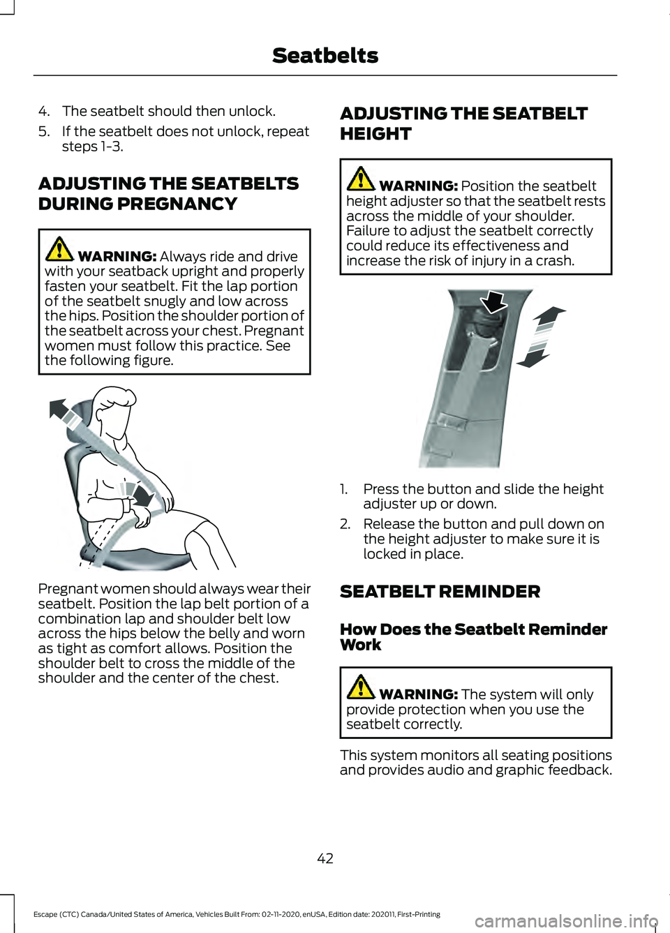
the following figure. Pregnant women should always wear their
seatbelt. Position the lap belt portion of a
combination lap and shoulder belt low
across the hips below the belly and worn
as tight as comfort allows. Position the
shoulder belt to cross the middle of the
shoulder and the center of the chest. ADJUSTING THE SEATBELT
HEIGHT WARNING:
Position the seatbelt
height adjuster so that the seatbelt rests
across the middle of your shoulder.
Failure to adjust the seatbelt correctly
could reduce its effectiveness and
increase the risk of injury in a crash. 1. Press the button and slide the height
adjuster up or down.
2. Release the button and pull down on the height adjuster to make sure it is
locked in place.
SEATBELT REMINDER
How Does the Seatbelt Reminder
Work WARNING:
The system will only
provide protection when you use the
seatbelt correctly.
This system monitors all seating positions
and provides audio and graphic feedback.
42
Escape (CTC) Canada/United States of America, Vehicles Built From: 02-11-2020, enUSA, Edition date: 202011, First-Printing SeatbeltsE142590 E200161
Page 47 of 589

When the initial warning expires for the
driver, more warnings are provided for the
driver and front passenger. This warning
tone sounds if you or your front passenger
do not fasten the seatbelt buckle and the
vehicle speed exceeds 6 mph (10 km/h).
This tone also sounds if an occupant
unfastens the rear seatbelt buckle or it
becomes unfastened.
Switching the Seatbelt Reminder
On and Off WARNING:
While the system
allows you to deactivate it, this system
is designed to improve your chances of
being safely belted and surviving an
accident. We recommend you leave the
system activated for yourself and others
who may use the vehicle.
Note: The driver and front passenger
warnings switch off independently. When
you perform this procedure for one seating
position, do not buckle the other position as
this cancels the process.
Read Steps 1 - 4 before proceeding with
the programming procedure.
Make sure that:
• You set the parking brake.
• The transmission is in park (P).
• The ignition is off.
• You close all vehicle doors.
• You unfasten the driver and front
passenger seatbelts.
1. Switch the ignition on. Do not start the
engine. 2. Wait about one minute until the
seatbelt warning light switches off.
After Step 2, wait an additional five
seconds before proceeding with Step
3. Once you start Step 3, you must
complete the procedure within 60
seconds.
3. For the seating position you are switching off, fasten then unfasten the
seatbelt three times at a moderate
speed, ending in the unfastened state.
After Step 3, the seatbelt warning light
switches on.
4. When the seatbelt warning light is on, fasten then unfasten the seatbelt. After
Step 4, the seatbelt warning light
flashes for confirmation.
This switches the feature off for that
seating position if it is currently on.
This switches the feature on for that
seating position if it is currently off.
CHECKING THE SEATBELTS
Check the seatbelts and child restraints
periodically to make sure they work
properly and are not damaged. Make sure
there are no nicks, tears or cuts. Replace if
necessary.
Check the following seatbelt assemblies
after a crash.
• Retractors.
• Buckles.
• Front seatbelt buckle assemblies.
• Shoulder belt height adjusters.
• Shoulder belt guide on seat backrest.
• Child restraint LATCH and tether
anchors.
• Attaching hardware.
44
Escape (CTC) Canada/United States of America, Vehicles Built From: 02-11-2020, enUSA, Edition date: 202011, First-Printing Seatbelts
Page 85 of 589

Vehicles With a Trailer Hitch
The detection area is on the left-hand side
and right-hand side of the hitch, between
the exhaust and the hitch.
Note:
Allow the power system to open the
liftgate. Manually pushing or pulling the
liftgate may activate the system ’s obstacle
detection feature and stop the power
operation or reverse its direction, replicate
a strut failure, or damage mechanical
components.
Note: Any physical actions that mimic a
kicking motion such as splashing water,
trailer chains or vacuum hoses may cause
the hands-free liftgate to activate. Switch
the power liftgate off through your vehicle
settings or keep the passive key away from
the rear bumper detection area.
SETTING THE LIFTGATE
OPENING HEIGHT
1. Open the liftgate.
2. Stop the liftgate movement by pressing
the control button on the liftgate when
it reaches the desired height.
Note: Once the liftgate stops moving, you
can manually move it to the desired height.
3. Press and hold the control button on the liftgate until a tone sounds,
indicating programming is complete. Note:
You can only use the liftgate control
button to program the height.
Note: You cannot program the height if the
liftgate position is too low.
4. The power liftgate now opens at the programmed height. To change the
programmed height, repeat the steps.
Note: You can fully open the liftgate by
manually pushing it upward to the
maximum open position if it opens in a
lower position.
Note: The system recalls the new
programmed height until you reprogram it,
even if you disconnect the battery.
CLOSING THE LIFTGATE
Closing the Liftgate From Inside
Your Vehicle WARNING: Make sure all persons
are clear of the power liftgate area
before using the power liftgate control. With the transmission in park
(P), press the button on the
instrument panel.
Note: Make sure that you close the liftgate
before operating or moving your vehicle,
especially in an enclosure, like a garage or
a parking structure. This could damage the
liftgate and its components.
Note: Make sure the area behind your
vehicle is free from obstruction and that
there is enough room for you to operate the
liftgate. Objects too close to your vehicle,
for example a wall, garage door or another
vehicle may come into contact with the
moving liftgate. This could damage the
liftgate and its components.
Note: Make sure that you fully close the
liftgate to prevent cargo from falling out.
82
Escape (CTC) Canada/United States of America, Vehicles Built From: 02-11-2020, enUSA, Edition date: 202011, First-Printing Liftgate - Vehicles With: Power LiftgateE310718 E138633
Page 154 of 589

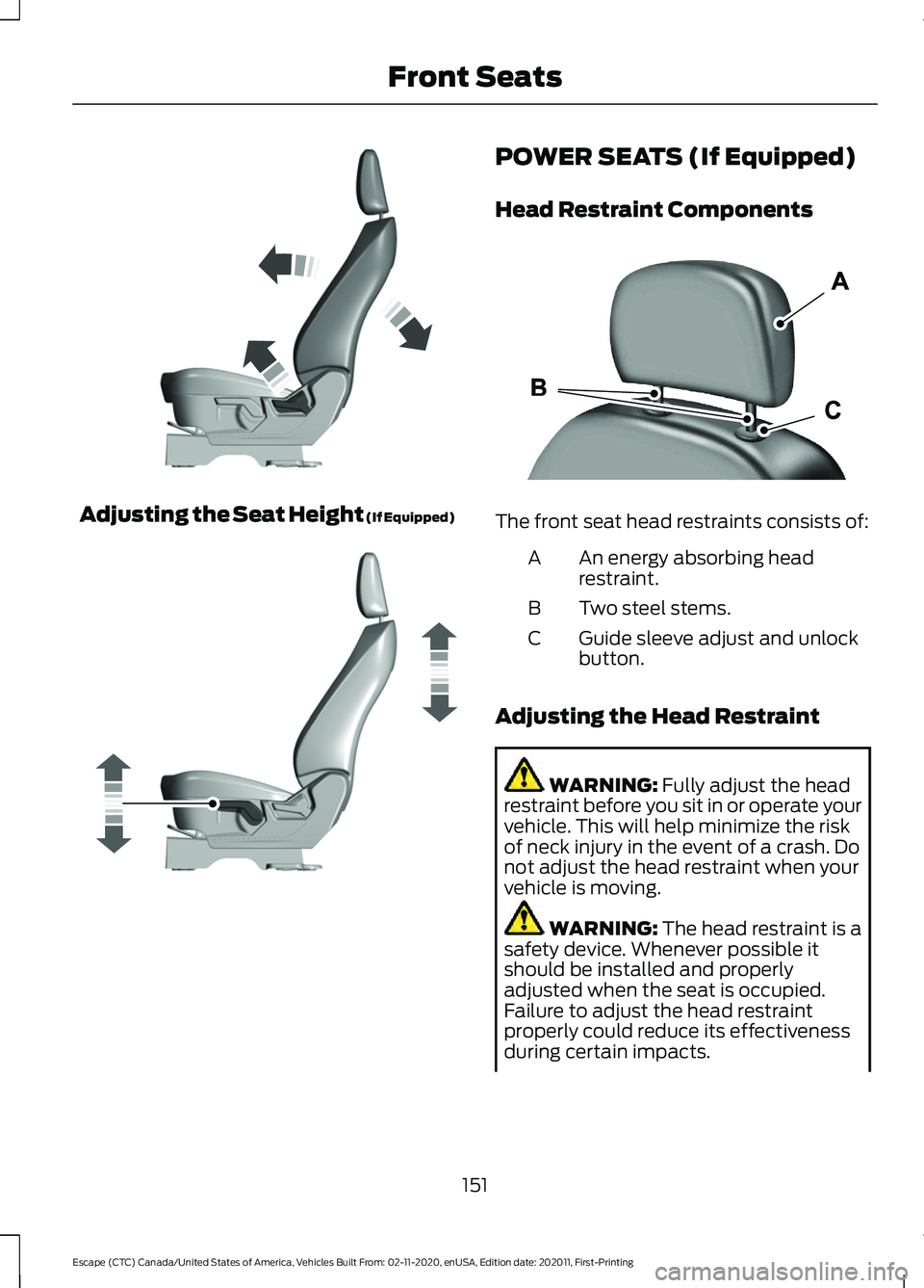
Adjusting the Seat Height (If Equipped) POWER SEATS (If Equipped)
Head Restraint Components
The front seat head restraints consists of:
An energy absorbing head
restraint.
A
Two steel stems.
B
Guide sleeve adjust and unlock
button.
C
Adjusting the Head Restraint WARNING: Fully adjust the head
restraint before you sit in or operate your
vehicle. This will help minimize the risk
of neck injury in the event of a crash. Do
not adjust the head restraint when your
vehicle is moving. WARNING:
The head restraint is a
safety device. Whenever possible it
should be installed and properly
adjusted when the seat is occupied.
Failure to adjust the head restraint
properly could reduce its effectiveness
during certain impacts.
151
Escape (CTC) Canada/United States of America, Vehicles Built From: 02-11-2020, enUSA, Edition date: 202011, First-Printing Front SeatsE293558 E293554 E291139
Page 156 of 589

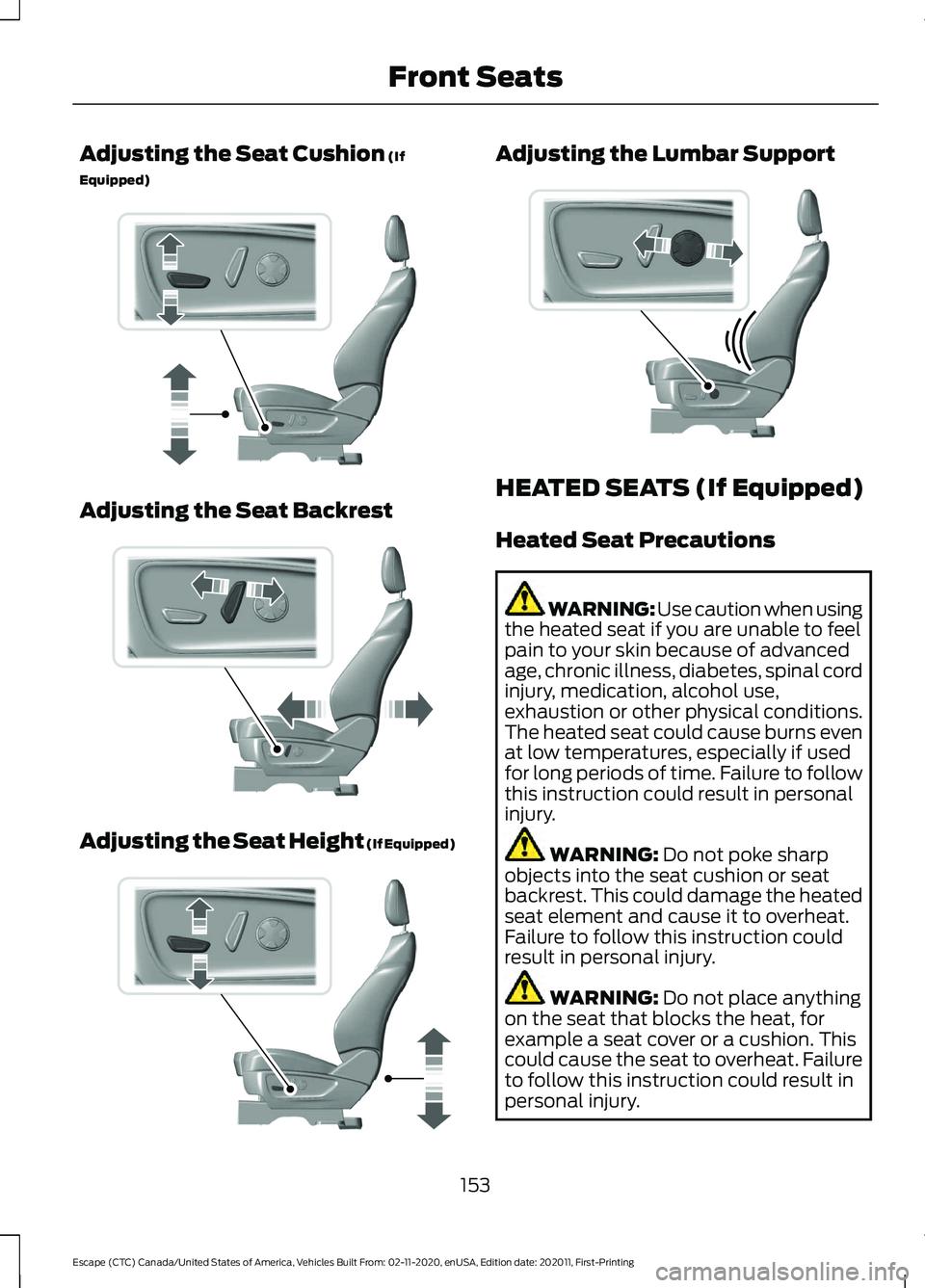
Adjusting the Seat Cushion (If
Equipped) Adjusting the Seat Backrest
Adjusting the Seat Height (If Equipped) Adjusting the Lumbar Support
HEATED SEATS (If Equipped)
Heated Seat Precautions
WARNING: Use caution when using
the heated seat if you are unable to feel
pain to your skin because of advanced
age, chronic illness, diabetes, spinal cord
injury, medication, alcohol use,
exhaustion or other physical conditions.
The heated seat could cause burns even
at low temperatures, especially if used
for long periods of time. Failure to follow
this instruction could result in personal
injury. WARNING:
Do not poke sharp
objects into the seat cushion or seat
backrest. This could damage the heated
seat element and cause it to overheat.
Failure to follow this instruction could
result in personal injury. WARNING:
Do not place anything
on the seat that blocks the heat, for
example a seat cover or a cushion. This
could cause the seat to overheat. Failure
to follow this instruction could result in
personal injury.
153
Escape (CTC) Canada/United States of America, Vehicles Built From: 02-11-2020, enUSA, Edition date: 202011, First-Printing Front SeatsE298771 E298773 E298772 E298774
Page 351 of 589

ADJUSTING THE HEADLAMPS
Vertical Aim Adjustment
The headlamps on your vehicle are
properly aimed at the assembly plant. If
your vehicle has been in an accident, the
alignment of your headlamps should be
checked by your authorized dealer.
8 feet (2.4 meters)
A
Center height of lamp to ground
B
25 feet (7.6 meters)
C
Horizontal reference line
D
1. Park the vehicle directly in front of a wall or screen on a level surface,
approximately 25 ft (7.6 m) away.
2. Measure the height of the headlamp bulb center from the ground and mark
an
8 ft (2.4 m) horizontal reference line
on the vertical wall or screen at this
height.
Note: To see a clearer light pattern for
adjusting, you may want to block the light
from one headlamp when adjusting the
other.
3. Switch on the low beam headlamps to
illuminate the wall or screen and open
the hood. 4. On the wall or screen you will observe
a flat zone of high intensity light
located at the top of the right hand
portion of the beam pattern. If the top
edge of the high intensity light zone is
not at the horizontal reference line, the
headlamp does need to be adjusted. 5. Locate the vertical adjuster on each
headlamp. Using a Phillips #2
screwdriver, turn the adjuster either
clockwise or counterclockwise in order
to aim the headlamp. The horizontal
edge of the brighter light should touch
the horizontal reference line.
6. Close the hood and switch off the lamps.
Horizontal Aim Adjustment
Horizontal aim is not required for this
vehicle and is non-adjustable.
348
Escape (CTC) Canada/United States of America, Vehicles Built From: 02-11-2020, enUSA, Edition date: 202011, First-Printing MaintenanceE142592 E142465 E307889
Page 365 of 589

Information on P Type Tires
P215/65R15 95H is an example of
a tire size, load index and speed
rating. The definitions of these
items are listed below. (Note that
the tire size, load index and speed
rating for your vehicle may be
different from this example.)
A.
P: Indicates a tire, designated
by the Tire and Rim Association,
that may be used for service on
cars, sport utility vehicles,
minivans and light trucks. Note:
If
your tire size does not begin with
a letter this may mean it is
designated by either the European
Tire and Rim Technical
Organization or the Japan Tire
Manufacturing Association. B.
215:
Indicates the nominal
width of the tire in millimeters
from sidewall edge to sidewall
edge. In general, the larger the
number, the wider the tire.
C. 65:
Indicates the aspect ratio
which gives the tire's ratio of
height to width.
D. R:
Indicates a radial type tire.
E. 15:
Indicates the wheel or rim
diameter in inches. If you change
your wheel size, you will have to
purchase new tires to match the
new wheel diameter.
F. 95:
Indicates the tire's load
index. It is an index that relates to
how much weight a tire can carry.
You may find this information in
your owner ’s manual. If not,
contact a local tire dealer.
Note: You may not find this
information on all tires because it
is not required by federal law.
G. H:
Indicates the tire's speed
rating. The speed rating denotes
the speed at which a tire is
designed to be driven for extended
periods of time under a standard
condition of load and inflation
pressure. The tires on your vehicle
may operate at different
conditions for load and inflation
pressure. These speed ratings may
need to be adjusted for the
difference in conditions. The
ratings range from
81 mph
(130 km/h) to 186 mph
(299 km/h)
. These ratings are
listed in the following chart.
362
Escape (CTC) Canada/United States of America, Vehicles Built From: 02-11-2020, enUSA, Edition date: 202011, First-Printing Wheel and Tire InformationH
I
J
KL
M
A
B
CDEFGE142543