2021 FORD E-450 lock
[x] Cancel search: lockPage 216 of 301

3. Cycle the ignition to the on position
with the engine off.
4. Turn the hazard flashers on then off three times. You must accomplish this
within 10 seconds. If you successfully
enter the reset mode, the horn sounds
once, the system indicator flashes and
a message shows in the information
display. If this does not occur, please
try again starting at step 2. If after
repeated attempts to enter the reset
mode, the horn does not sound, the
system indicator does not flash and no
message shows in the information
display, have the system checked as
soon as possible.
5. Train the tire pressure monitoring system sensors in the tires using the
following system reset sequence
starting with the left front tire in the
following clockwise order: Left front -
driver side front tire, Right front -
passenger side front tire, Right rear -
passenger side rear tire, Left rear -
driver side rear tire.
6. Remove the valve cap from the valve stem on the left front tire. Decrease the
air pressure until the horn sounds.
Note: The single horn tone confirms that
the sensor identification code has been
learned by the module for this position. If
you hear a double horn, the reset procedure
was unsuccessful, and you must repeat it.
7. Remove the valve cap from the valve stem on the right front tire. Decrease
the air pressure until the horn sounds.
8. Remove the valve cap from the valve stem on the right rear tire. Decrease the
air pressure until the horn sounds. 9. Remove the valve cap from the valve
stem on the left rear tire. Decrease the
air pressure until the horn sounds.
Training is complete after the horn
sounds for the last tire trained, driver
side rear tire, the system indicator
stops flashing, and a message shows
in the information display.
10. Turn the ignition off. If you hear two short tones, the reset procedure was
unsuccessful and you must repeat it.
If you hear two short beeps when the
ignition is off after repeating the
procedure, have the system checked
as soon as possible
11. Set all four tires to the recommended
air pressure as indicated on the
Safety Compliance Certification
Label, affixed to either the door hinge
pillar, door-latch post, or the door
edge that meets the door-latch post,
next to the driver seating position or
Tire Label located on the B-Pillar or
the edge of the driver door.
CHANGING A ROAD WHEEL (IF
EQUIPPED) WARNING:
To determine the
required pressure(s) for your vehicle, see
the Safety Compliance Certification
Label (on the door hinge pillar,
door-latch post or the door edge that
meets the door-latch post, next to the
driver seat) or the Tire Label on the
B-Pillar or the edge of the driver door.
Note: You should only use tire sealants in
roadside emergencies as they may cause
damage to the tire pressure monitoring
system sensor.
213
E-Series (TE4) Canada/United States of America, enUSA, Edition date: 201910, First-Printing Wheels and Tires
Page 218 of 301

When driving with the full-size dissimilar
spare wheel and tire assembly, do not:
•
Exceed 70 mph (113 km/h).
• Use more than one dissimilar spare
wheel and tire assembly at a time.
• Use commercial car washing
equipment.
• Use snow chains on the end of the
vehicle with the dissimilar spare wheel
and tire assembly.
The usage of a full-size dissimilar spare
wheel and tire assembly can lead to
impairment of the following:
• Handling, stability and braking
performance.
• Comfort and noise.
• Ground clearance and parking at curbs.
• Winter weather driving capability.
• Wet weather driving capability.
• All-wheel driving capability.
When driving with the full-size dissimilar
spare wheel and tire assembly additional
caution should be given to:
• Towing a trailer.
• Driving vehicles equipped with a
camper body.
• Driving vehicles with a load on the
cargo rack.
Drive cautiously when using a full-size
dissimilar spare wheel and tire assembly
and seek service as soon as possible.
Tire Change Procedure WARNING:
When one of the front
wheels is off the ground, the
transmission alone will not prevent the
vehicle from moving or slipping off the
jack, even if the transmission is in park
(P). WARNING:
To help prevent your
vehicle from moving when changing a
wheel, shift the transmission into park
(P), set the parking brake and use an
appropriate block or wheel chock to
secure the wheel diagonally opposite to
the wheel being changed. For example,
when changing the front left wheel,
place an appropriate block or wheel
chock on the right rear wheel. WARNING:
Do not get under a
vehicle that is only supported by a
vehicle jack. WARNING:
Do not attempt to
change a tire on the side of the vehicle
close to moving traffic. Pull far enough
off the road to avoid the danger of being
hit when operating the jack or changing
the wheel. WARNING:
Always use the jack
provided as original equipment with your
vehicle. If using a jack other than the one
provided, make sure the jack capacity is
adequate for the vehicle weight,
including any vehicle cargo or
modifications. If you are unsure if the jack
capacity is adequate, contact the
authorized dealer.
Note: Passengers should not remain in your
vehicle when the vehicle is being jacked.
Removing the flat wheel and tire
1. Park on a level surface, set the parking
brake and activate the hazard flashers.
2. Place the transmission in park (P) and
turn the engine off.
215
E-Series (TE4) Canada/United States of America, enUSA, Edition date: 201910, First-Printing Wheels and Tires
Page 219 of 301

3.
Block both directions of the wheel that
is diagonally opposite to the wheel that
is being lifted.
4. Remove the spare tire and jack from the storage location.
5. Remove the wheel trim (if equipped) by inserting the tapered end of the lug
nut wrench behind the wheel cover or
hubcap and twist it off.
6. Loosen each wheel lug nut one-half turn counterclockwise, but do not
remove them until the wheel is raised
off the ground.
Jacking location Front axle jacking point: Place the jack
under the pin on the front surface of the
front axle. Note:
Do not place the jack under or on the
steering linkage. Rear axle jacking points: All models except
E-350 and E-450 dual rear wheel.
Rear axle jacking points: E-350 and E-450
dual rear wheel.
Installing the spare wheel and tire
1. Refer to the diagrams above to locate
the correct jacking point for your
vehicle.
2. Raise the vehicle by using the jack handle to turn the jack nut clockwise.
Once the flat tire is raised above the
ground, remove the lug nuts with the
lug wrench.
216
E-Series (TE4) Canada/United States of America, enUSA, Edition date: 201910, First-Printing Wheels and TiresE142551 E201348 E201346 E201347
Page 220 of 301

3. Replace the flat tire with the spare,
making sure the valve stem of the
spare is facing outward when replacing
a front wheel or the rear wheel position
on vehicles with single rear wheel
fitments. For vehicles with dual rear
wheels, the valve stem of the spare
must face outward when replacing an
inner wheel, but must face inward
when replacing an outboard wheel.
4. Reinstall the lug nuts until the wheel is
snug against the hub. Do not fully
tighten the lug nuts until the vehicle
has been lowered
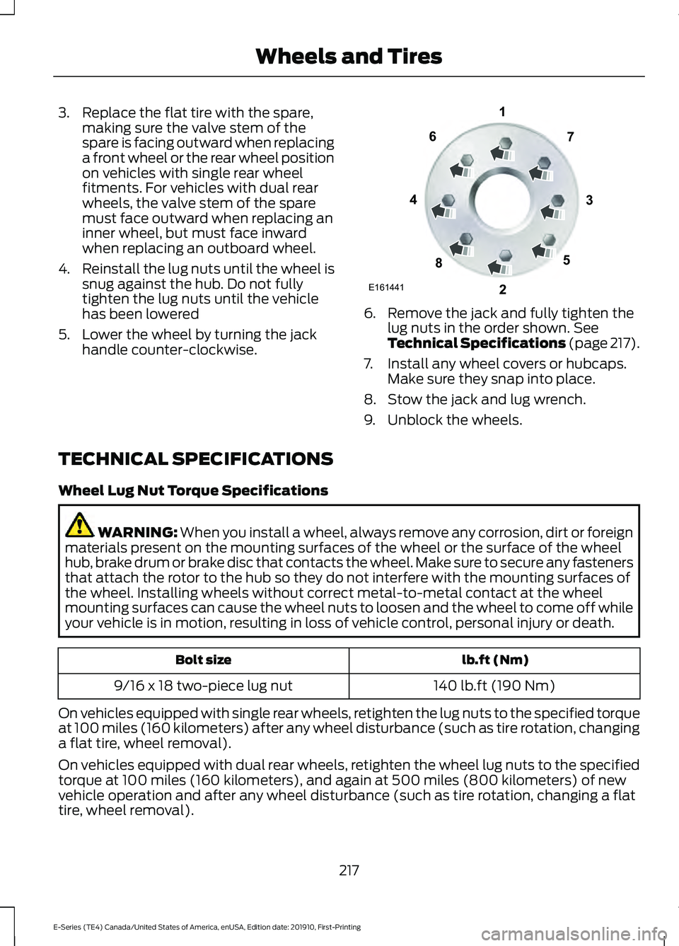
5. Lower the wheel by turning the jack handle counter-clockwise. 6. Remove the jack and fully tighten the
lug nuts in the order shown. See
Technical Specifications (page 217).
7. Install any wheel covers or hubcaps. Make sure they snap into place.
8. Stow the jack and lug wrench.
9. Unblock the wheels.
TECHNICAL SPECIFICATIONS
Wheel Lug Nut Torque Specifications WARNING: When you install a wheel, always remove any corrosion, dirt or foreign
materials present on the mounting surfaces of the wheel or the surface of the wheel
hub, brake drum or brake disc that contacts the wheel. Make sure to secure any fasteners
that attach the rotor to the hub so they do not interfere with the mounting surfaces of
the wheel. Installing wheels without correct metal-to-metal contact at the wheel
mounting surfaces can cause the wheel nuts to loosen and the wheel to come off while
your vehicle is in motion, resulting in loss of vehicle control, personal injury or death. lb.ft (Nm)
Bolt size
140 lb.ft (190 Nm)
9/16 x 18 two-piece lug nut
On vehicles equipped with single rear wheels, retighten the lug nuts to the specified torque
at 100 miles (160 kilometers) after any wheel disturbance (such as tire rotation, changing
a flat tire, wheel removal).
On vehicles equipped with dual rear wheels, retighten the wheel lug nuts to the specified
torque at 100 miles (160 kilometers), and again at 500 miles (800 kilometers) of new
vehicle operation and after any wheel disturbance (such as tire rotation, changing a flat
tire, wheel removal).
217
E-Series (TE4) Canada/United States of America, enUSA, Edition date: 201910, First-Printing Wheels and TiresE161441
13
4
27
6
5
8
Page 232 of 301

Materials
Specification
Name
MERCON® LV WSS-M2C938-A
Motorcraft® MERCON® LV Automatic Transmission
Fluid (U.S.)
Motorcraft® MERCON® LV Automatic Transmission
Fluid / Huile pour boîte automatique MERCON® LV
Motorcraft® (Canada)
XT-10-QLVC (U.S.)
CXT-10-LV6 (Canada)
Door Weatherstrips
Materials Specification
Name
ESR-M13P4-A
Motorcraft® Silicone Spray Lubricant (U.S.)
Motorcraft® Silicone Lubricant / Lubrifiant à la
silicone Motorcraft® (Canada)
XL-6 (U.S.)
CXC-90-B (Canada)
Locks
Materials Specification
Name
-
Motorcraft® Penetrating and Lock Lubricant (U.S.)
Motorcraft® Penetrating Fluid / Liquide dégrippant
Motorcraft® (Canada)
XL-1 (U.S.)
CXC-51-A (Canada)
Dana Limited Slip Axle M70FF (M267FF)
Capacities Quantity
Variant
3.28 qt (3.1 L)1
E-350
1 Fill Dana rear axles to 0.24–0.55 in (6– 14 mm) below the bottom of the fill hole.
229
E-Series (TE4) Canada/United States of America, enUSA, Edition date: 201910, First-Printing Capacities and Specifications
Page 245 of 301

SiriusXM satellite radio is a
subscription-based satellite radio service
that broadcasts a variety of music, sports,
news, weather, traffic and entertainment
programming. Your factory-installed
SiriusXM satellite radio system includes
hardware and a limited subscription term,
which begins on the date of sale or lease
of your vehicle. See an authorized dealer
for availability.
For more information on extended
subscription terms (a service fee is
required), the online media player and a
complete list of SiriusXM satellite radio
channels, and other features, please visit
www.siriusxm.com in the United States,
www.siriusxm.ca in Canada, or call
SiriusXM at 1-888-539-7474.
Satellite Radio Electronic Serial
Number (ESN)
You need your ESN to activate, modify or
track your satellite radio account. When in
satellite radio mode, tune to channel 0.
Troubleshooting Action
Condition
Message
No action required. This
message should disappear
shortly.
Radio requires more than
two seconds to produce
audio for the selected
channel.
Acquiring…
If this message does not
clear shortly, or with an igni-
tion key cycle, your receiver
may have a fault. See an
authorized dealer for service.
There is an internal module
or system failure present.
Satellite antenna fault
SIRIUS system failure
Tune to another channel or
choose another preset.
The channel is no longer
available.
Invalid Channel
Contact SiriusXM at 1-888-
539-7474 to subscribe to
the channel, or tune to
another channel.
Your subscription does not
include this channel.
Unsubscribed Channel
The signal is blocked. When
you move into an open area,
the signal should return.
The signal is lost from the
SiriusXM satellite or Siri-
usXM tower to your vehicle
antenna.
No Signal
No action required. The
process may take up to
three minutes.
Update of channel
programming in progress.
Updating…
242
E-Series (TE4) Canada/United States of America, enUSA, Edition date: 201910, First-Printing Audio System (If Equipped)
Page 246 of 301

Action
Condition
Message
Contact SiriusXM at 1-888-
539-7474 to resolve
subscription issues.
Your satellite service is no
longer available.
Questions? Call
1-888-539-7474
Use the channel guide to
turn off the Lock or Skip
function on that station.
All the channels in the
selected category are either
skipped or locked.
None found
Check Channel Guide
No action required.
SiriusXM has updated the
channels available for your
vehicle.
Subscription Updated
STREAMING BLUETOOTH
AUDIO
Selecting a Bluetooth Source Press the button to display the
menu.
Repeatedly press the button to scroll to
the Bluetooth device.
Press the OK button. Press the button to play the
track. Press the button again to
pause the track.
Press the button to skip to the
next track.
Press and hold the button to fast
forward through the track. Press the button once to return
to the beginning of the track.
Repeatedly press the button to
return to previous tracks.
Press and hold the button to fast rewind.
Note: Not all functions are supported by all
phones. PLAYING MEDIA FROM A USB
DEVICE
Supported Audio File Formats
You can play audio file formats including
MP3, WMA, WAV, M4A, M4B, AAC, and
FLAC.
Note:
The NTFS file system is not
supported.
Selecting the USB Device Press the button to display the
menu.
Repeatedly press the button to scroll to
your USB device.
Press the
OK button.
Playing from the USB Device Press the button to play a track.
Press the button again to pause
the track.
Press the button to skip to the
next track.
Press and hold the button to fast
forward through the track.
243
E-Series (TE4) Canada/United States of America, enUSA, Edition date: 201910, First-Printing Audio System
(If Equipped)E100027 E100027
Page 249 of 301

AUXILIARY SWITCHES (IF
EQUIPPED)
For maximum vehicle performance, keep
the following information in mind when
adding accessories or equipment to your
vehicle:
• When adding accessories, equipment,
passengers and luggage to your
vehicle, do not exceed the total weight
capacity of the vehicle or of the front
or rear axle (GVWR or GAWR as
indicated on the Safety Compliance
Certification label). Ask an authorized
dealer for specific weight information.
• The Federal Communications
Commission (FCC) and Canadian
Radio Telecommunications
Commission (CRTC) regulate the use
of mobile communications systems
equipped with radio transmitters, for
example, two-way radios, telephones
and theft alarms. Any such equipment
installed in your vehicle should comply
with Federal Communications
Commission (FCC) and Canadian
Radio Telecommunications
Commission (CRTC) regulations, and
should be installed by an authorized
dealer.
• An authorized dealer needs to install
mobile communications systems.
Improper installation may harm the
operation of your vehicle, particularly
if the manufacturer did not design the
mobile communication system
specifically for automotive use.
• If you or an authorized Ford dealer add
any non-Ford electrical or electronic
accessories or components to your
vehicle, you may adversely affect
battery performance and durability. In
addition, you may also adversely affect
the performance of other electrical
systems in the vehicle. The auxiliary switch option package
provides four switches, mounted in the
center of the instrument panel. These
switches operate when the vehicle is
running or from battery power, depending
on the switchable PDB fuse locations #82
and #83. Ford recommends, however, that
the engine remain running to maintain
battery charge when using the auxiliary
switches for extended periods of time or
higher current draws.
When switched on, the auxiliary switches
provide 20 amps or 40 amps of electrical
battery power for a variety of personal or
commercial uses.
The switches include the fuse and relay kit.
This kit contains the required fuses and
relays that an authorized technician needs
to install into the power distribution box,
located under the hood. Refer to the
instruction sketch included in the kit.
Contact an authorized dealer for service.
Each switch includes a power lead (a
blunt-cut and sealed wire) located in the
underhood cowl shield above the engine
block powertrain control module.
The power leads are coded as follows:
246
E-Series (TE4) Canada/United States of America, enUSA, Edition date: 201910, First-Printing AccessoriesE163431