2021 DODGE CHALLENGER tire pressure
[x] Cancel search: tire pressurePage 240 of 328

238IN CASE OF EMERGENCY
(E) After Driving:
Pull over to a safe location before continuing
Úpage 236.
1. Push in the Mode Select Knob (6) and turn to the Air Mode position.
2. Uncoil the power plug and insert the plug into the vehicle's 12 Volt power outlet.
3. Uncoil the Air Pump Hose (8) (black in color) and screw the fitting at the end of hose on to
the valve stem.
4. Check the pressure in the tire by reading the Pressure Gauge (5).
If tire pressure is less than 19 psi (1.3 Bar):
The tire is too badly damaged. Do not attempt to
drive the vehicle further. Call for assistance.
If the tire pressure is 19 psi (1.3 Bar) or higher:
1. Push the Power Button (3) to turn on Tire Service Kit and inflate the tire to the pressure
indicated on the tire and loading information
label on the driver-side door opening.
NOTE:If the tire becomes overinflated, push the Deflation
Button (2) to reduce the tire pressure to the recom -
mended inflation pressure before continuing. 2. Disconnect the Tire Service Kit from the valve
stem, reinstall the cap on the valve stem and
unplug from 12 Volt outlet.
3. Place the Tire Service Kit in its proper storage area in the vehicle.
4. Have the tire inspected and repaired or replaced at the earliest opportunity at an
authorized dealer or tire service center.
5. Remove the Speed Limit sticker from the instrument panel after the tire has been
repaired.
6. Replace the Sealant Bottle (1) and Sealant Hose (4) assembly at an authorized dealer as
soon as possible.
NOTE:When having the tire serviced, advise the autho -
rized dealer or service center that the tire has been
sealed using the Tire Service Kit.
(F) Sealant Bottle And Hose Replacement:
1. Uncoil the Sealant Hose (4) (clear in color).
2. Locate the round Sealant Bottle release button in the recessed area under the sealant bottle.
3. Push the Sealant Bottle release button. The Sealant Bottle (1) will pop up. Remove the
bottle and dispose of it accordingly. 4. Clean any remaining sealant from the Tire
Service Kit housing.
5. Position the new Sealant Bottle (1) in the housing so that the Sealant Hose (4) aligns
with the hose slot in the front of the housing.
Push the bottle into the housing. An audible
click will be heard indicating the bottle is
locked into place.
6. Verify that the cap is installed on the fitting at the end of the Sealant Hose (4) and return the
hose to its storage area (located on the bottom
of the air pump).
7. Return the Tire Service Kit to its storage location in the vehicle.
JUMP STARTING
If your vehicle has a discharged battery, it can be
jump started using a set of jumper cables and a
battery in another vehicle, or by using a portable
battery booster pack. Jump starting can be
dangerous if done improperly, so please follow the
procedures in this section carefully.
WARNING!
Do not attempt jump starting if the battery is
frozen. It could rupture or explode and cause
personal injury.
21_LA_OM_EN_USC_t.book Page 238
Page 245 of 328

IN CASE OF EMERGENCY243
FREEING A STUCK VEHICLE
If your vehicle becomes stuck in mud, sand, or
snow, it can often be moved using a rocking
motion. Turn the steering wheel right and left to
clear the area around the front wheels. For
vehicles with automatic transmission, push and
hold the lock button on the gear selector. Then
shift back and forth between DRIVE and REVERSE
(with automatic transmission) or FIRST gear and
REVERSE (with manual transmission), while gently
pressing the accelerator. Use the least amount of
accelerator pedal pressure that will maintain the
rocking motion, without spinning the wheels or
racing the engine.
NOTE:For vehicles with automatic transmission: Shifts
between DRIVE and REVERSE can only be
achieved at wheel speeds of 5 mph (8 km/h) or
less. Whenever the transmission remains in
NEUTRAL for more than two seconds, you must
press the brake pedal to engage DRIVE or
REVERSE.
Push the ESC OFF button to place the Electronic
Stability Control (ESC) system in “Partial OFF”
mode, before rocking the vehicle Ú page 180.
Once the vehicle has been freed, push the ESC OFF
button again to restore “ESC On” mode.
CAUTION!
Racing the engine or spinning the wheels may
lead to transmission overheating and failure.
Allow the engine to idle with the transmission in
NEUTRAL for at least one minute after every five
rocking-motion cycles. This will minimize
overheating and reduce the risk of clutch or
transmission failure during prolonged efforts to
free a stuck vehicle.
WARNING!
Fast spinning tires can be dangerous. Forces
generated by excessive wheel speeds may
cause damage, or even failure, of the axle and
tires. A tire could explode and injure someone.
Do not spin your vehicle's wheels faster than
30 mph (48 km/h) or for longer than 30
seconds continuously without stopping when
you are stuck and do not let anyone near a
spinning wheel, no matter what the speed.
CAUTION!
When “rocking” a stuck vehicle by shifting
between DRIVE / FIRST gear and REVERSE, do
not spin the wheels faster than 15 mph
(24 km/h), or drivetrain damage may result.
Revving the engine or spinning the wheels too
fast may lead to transmission overheating and
failure. It can also damage the tires. Do not
spin the wheels above 30 mph (48 km/h)
while in gear (no transmission shifting occur -
ring).
7
21_LA_OM_EN_USC_t.book Page 243
Page 248 of 328

246
SERVICING AND MAINTENANCE
SCHEDULED SERVICING
3.6L AND 5.7L ENGINES
These engines are equipped with an automatic oil
change indicator system. The oil change indicator
system will remind you that it is time to take your
vehicle in for scheduled maintenance.
Based on engine operation conditions, the oil
change indicator message will illuminate. This
means that service is required for the vehicle.
Operating conditions such as frequent short-trips,
trailer tow, and extremely hot or cold ambient
temperatures will influence when the “Change Oil”
or “Oil Change Required” message is displayed.
Have your vehicle serviced as soon as possible,
within the next 500 miles (805 km).The “Oil Change Required” message will be
displayed in the instrument cluster and a single
chime will sound, indicating that an oil change is
necessary.
An authorized dealer will reset the oil change
indicator message after completing the scheduled
oil change.
NOTE:Under no circumstances should oil change
intervals exceed 10,000 miles (16,000 km),
12 months or 350 hours of engine run time,
whichever comes first. The 350 hours of engine
run or idle time is generally only a concern for fleet
customers.
Once A Month Or Before A Long Trip:
Check engine oil level.
Check windshield washer fluid level.
Check tire pressure and look for unusual wear
or damage. Rotate tires at the first sign of irreg
-
ular wear, even if it occurs before your next
scheduled service.
Check the fluid levels of the coolant reservoir,
brake master cylinder, and power steering (if
equipped) and fill as needed.
Check function of all interior and exterior lights.
21_LA_OM_EN_USC_t.book Page 246
Page 259 of 328

SERVICING AND MAINTENANCE257
T/A Air Filter Maintenance — If Equipped
Clean Engine Air Filter
The scheduled air filter cleaning interval is
30,000 miles (48,280 km), or if in a dusty
environment the engine air filter should be
checked periodically to ensure optimal air flow.
Cleaning your engine air filter with the
recommended Mopar® Performance Air Filter
Service Kit is not required if you can still see any
part the wire screen on the entire air filter
regardless of how dirty it may appear. When any
part of the wire screen is no longer visible on the air
filter, that is an indication it is time to clean the air
filter.
1. Spray the air filter with the recommended
Mopar® air filter cleaner and let sit for at
least 10 minutes to loosen dirt, before
rinsing.
NOTE:Never use strong detergents, high pressure, or
gasoline on air filter.
2. Rinse the air filter with cool low-pressure water applied from the inside (clean side) out in
order to flush the dirt out of the filter. Continue
to rinse the filter until all traces of the cleaner
have been removed.
NOTE:It may be necessary to repeat steps 1 and 2 if the
air filter is not completely clean.
3. After rinsing the air filter, gently shake off the excess water and allow air filter to dry
naturally. Do not apply oil until air filter is
completely dry.
NOTE:Do not use forced air pressure as it may damage
the filtering capabilities of the filter’s microfibers
and also void its warranty.
4. Using the Mopar® Performance Air Filter Service Kit, spray oil evenly along the crown of
each filter pleat holding the nozzle about
3 inches (76 mm) away from the air filter. One
spray per 2 square inches (1,290 square mm)
of air filter. With one complete coat of oil, let it
wick (saturate) for about 20 minutes, and if
required touch up any light areas on either
side of the filter.
AIR CONDITIONER MAINTENANCE
For best possible performance, your air conditioner
should be checked and serviced by an authorized
dealer at the start of each warm season. This
service should include cleaning of the condenser
fins and a performance test. Drive belt tension
should also be checked at this time.
WARNING!
Use only refrigerants and compressor lubri -
cants approved by the manufacturer for your
air conditioning system. Some unapproved
refrigerants are flammable and can explode,
injuring you. Other unapproved refrigerants or
lubricants can cause the system to fail,
requiring costly repairs. Refer to Warranty
Information Book, for further warranty infor -
mation.
The air conditioning system contains refrig -
erant under high pressure. To avoid risk of
personal injury or damage to the system,
adding refrigerant or any repair requiring lines
to be disconnected should be done by an
experienced technician.
CAUTION!
Do not use chemical flushes in your air
conditioning system as the chemicals can
damage your air conditioning components. Such
damage is not covered by the New Vehicle
Limited Warranty.8
21_LA_OM_EN_USC_t.book Page 257
Page 264 of 328

262SERVICING AND MAINTENANCE
Under normal operating conditions, the catalytic
converter will not require maintenance. However, it
is important to keep the engine properly tuned to
ensure proper catalyst operation and prevent
possible catalyst damage.
NOTE:Intentional tampering with emissions control
systems can result in civil penalties being
assessed against you.
In unusual situations involving grossly
malfunctioning engine operation, a scorching odor
may suggest severe and abnormal catalyst
overheating. If this occurs, stop the vehicle, turn off
the engine and allow it to cool. Service, including a
tune-up to manufacturer's specifications, should
be obtained immediately.
To minimize the possibility of catalytic converter
damage:
Do not shut off the engine or interrupt the igni-
tion when the transmission is in gear and the
vehicle is in motion.
Do not try to start the engine by pushing or
towing the vehicle.
Do not idle the engine with any spark plug wires
disconnected or removed, such as when diag -
nostic testing, or for prolonged periods during
very rough idle or malfunctioning operating
conditions.
NOTE:The vehicle exhaust system may be equipped with
an Electronic Exhaust Valve (EEV) system, if the
exhaust system is replaced with aftermarket
products a Malfunction Indicator Lamp (MIL) will
illuminate.
COOLING SYSTEM
Coolant Checks
Check engine coolant (antifreeze) protection every
12 months (before the onset of freezing weather,
where applicable). If the engine coolant is dirty, the
system should be drained, flushed, and refilled
with fresh Organic Additive Technology (OAT)
coolant (conforming to MS.90032) by an
authorized dealer. Check the front of the radiator
for any accumulation of bugs, leaves, etc. If dirty,
clean by gently spraying water from a garden hose
vertically down the face of the condenser.
Check the coolant recovery bottle tubing for brittle
rubber, cracking, tears, cuts, and tightness of the
connection at the bottle and radiator. Inspect the
entire system for leaks. DO NOT REMOVE THE
COOLANT PRESSURE CAP WHEN THE COOLING
SYSTEM IS HOT.
Cooling System — Drain, Flush And Refill
NOTE:Some vehicles require special tools to add coolant
properly. Failure to fill these systems properly
could lead to severe internal engine damage. If any
coolant is needed to be added to the system
please contact an authorized dealer.
WARNING!
You or others can be badly burned by hot
engine coolant (antifreeze) or steam from your
radiator. If you see or hear steam coming from
under the hood, do not open the hood until the
radiator has had time to cool. Never open a
cooling system pressure cap when the radi -
ator or coolant bottle is hot.
Keep hands, tools, clothing, and jewelry away
from the radiator cooling fan when the hood is
raised. The fan starts automatically and may
start at any time, whether the engine is
running or not.
When working near the radiator cooling fan,
disconnect the fan motor lead or turn the igni -
tion to the OFF mode. The fan is temperature
controlled and can start at any time the igni -
tion is in the ON mode.
21_LA_OM_EN_USC_t.book Page 262
Page 275 of 328

SERVICING AND MAINTENANCE273
F09 40 Amp Green –Power Locks
F10 30 Amp Pink –Driver Door Control Module
F11 30 Amp Pink –Passenger Door Control Module
F12 –20 Amp YellowCigar Lighter/IP APO/RR USB
(Selectable Fuse) *
F15 40 Amp Green –HVAC Blower
F16 20 Amp Blue –Left Spot Lamp – Police
F17 20 Amp Blue –Right Spot Lamp – Police
F18 30 Amp Pink –VISM MOD (Police)
F19 ––Spare
F20 ––Spare
F21 30 Amp Pink –Fuel Pump (Non 6.2L ADR)
F22 –5 Amp TanCyber Gateway Mod
F23 –10 Amp RedFuel Door */Diagnostic Port
F24 –10 Amp RedIntegrated Center Stack
F25 –10 Amp RedTire Pressure Monitor
F26 –15 Amp BlueTrans Mod (Charger Non- Police/300)
F27 –25 Amp ClearAmplifier *
F31 –25 Amp BreakerPower Seats *
F32 –15 Amp BlueHVAC Module/Cluster
Cavity Cartridge Fuse Mini-FuseDescription
* If Equipped
8
21_LA_OM_EN_USC_t.book Page 273
Page 281 of 328

SERVICING AND MAINTENANCE279
NOTE:On vehicles equipped with HID headlamps, when
the headlamps are turned on, there is a blue hue
to the lamps. This diminishes and becomes more
white after approximately 10 seconds, as the
system charges.
FRONT PARK/SIGNATURE LAMP
The Front Park/Signature function is part of the
headlamp assembly and use LED lamps that are
not serviceable separately. The headlamps must
be replaced as an assembly, see an authorized
dealer.
FRONT TURN/DRL LAMP
The Front Turn/DRL function is part of the
headlamp assembly and use LED lamps that are
not serviceable separately. The headlamps must
be replaced as an assembly, see an authorized
dealer.
FRONT/REAR SIDE MARKER LAMP
The Side Markers use LED lamps that are not
serviceable separately. The Side Markers must be
replaced as an assembly, see an authorized
dealer.
TAIL/TURN AND STOP LAMP
The Tail/Turn and Stop Lamps use LED lamps that
are not serviceable separately. The Tail/Turn and
Stop Lamps must be replaced as an assembly, see
an authorized dealer.
CENTER TAIL/BACKUP LAMP
The Center Tail/Backup Lamp use LED lamps that
are not serviceable separately. The Center Tail/
Backup Lamp must be replaced as an assembly;
see an authorized dealer.
CENTER HIGH MOUNTED STOP LAMP (CHMSL)
The CHMSL Lamp uses LED sources that are not
serviceable separately. The CHMSL Lamp must be
replaced as an assembly; see an authorized
dealer.
LICENSE LAMP
The License Lamp uses an LED source that is not
serviceable separately. The License Lamp must be
replaced as an assembly; see an authorized
dealer.
TIRES
TIRE SAFETY INFORMATION
Tire safety information will cover aspects of the
following information: Tire Markings, Tire
Identification Numbers, Tire Terminology and
Definitions, Tire Pressures, and Tire Loading.
WARNING!
A transient high voltage occurs at the bulb
sockets of HID headlamps when the headlamp
switch is turned ON. It may cause serious
electrical shock or electrocution if not serviced
properly. See an authorized dealer for service.
8
21_LA_OM_EN_USC_t.book Page 279
Page 282 of 328

280SERVICING AND MAINTENANCE
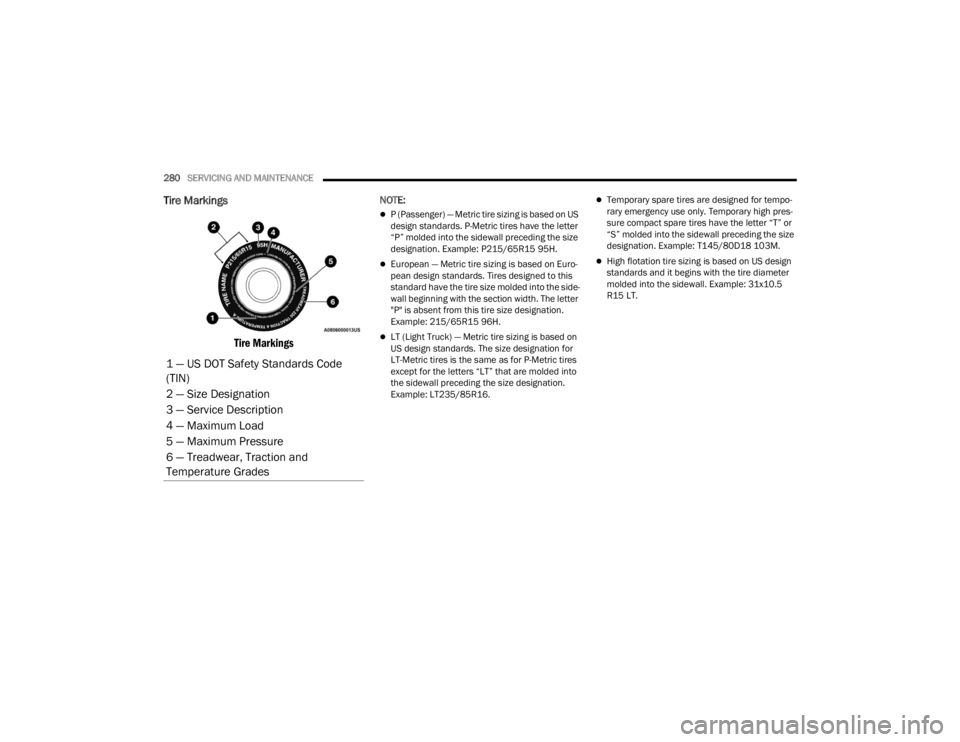
Tire Markings
Tire Markings
NOTE:
P (Passenger) — Metric tire sizing is based on US
design standards. P-Metric tires have the letter
“P” molded into the sidewall preceding the size
designation. Example: P215/65R15 95H.
European — Metric tire sizing is based on Euro -
pean design standards. Tires designed to this
standard have the tire size molded into the side -
wall beginning with the section width. The letter
"P" is absent from this tire size designation.
Example: 215/65R15 96H.
LT (Light Truck) — Metric tire sizing is based on
US design standards. The size designation for
LT-Metric tires is the same as for P-Metric tires
except for the letters “LT” that are molded into
the sidewall preceding the size designation.
Example: LT235/85R16.
Temporary spare tires are designed for tempo -
rary emergency use only. Temporary high pres -
sure compact spare tires have the letter “T” or
“S” molded into the sidewall preceding the size
designation. Example: T145/80D18 103M.
High flotation tire sizing is based on US design
standards and it begins with the tire diameter
molded into the sidewall. Example: 31x10.5
R15 LT.
1 — US DOT Safety Standards Code
(TIN)
2 — Size Designation
3 — Service Description
4 — Maximum Load
5 — Maximum Pressure
6 — Treadwear, Traction and
Temperature Grades
21_LA_OM_EN_USC_t.book Page 280