2021 CHRYSLER 300 mirror
[x] Cancel search: mirrorPage 50 of 268

48 GETTING TO KNOW YOUR VEHICLE
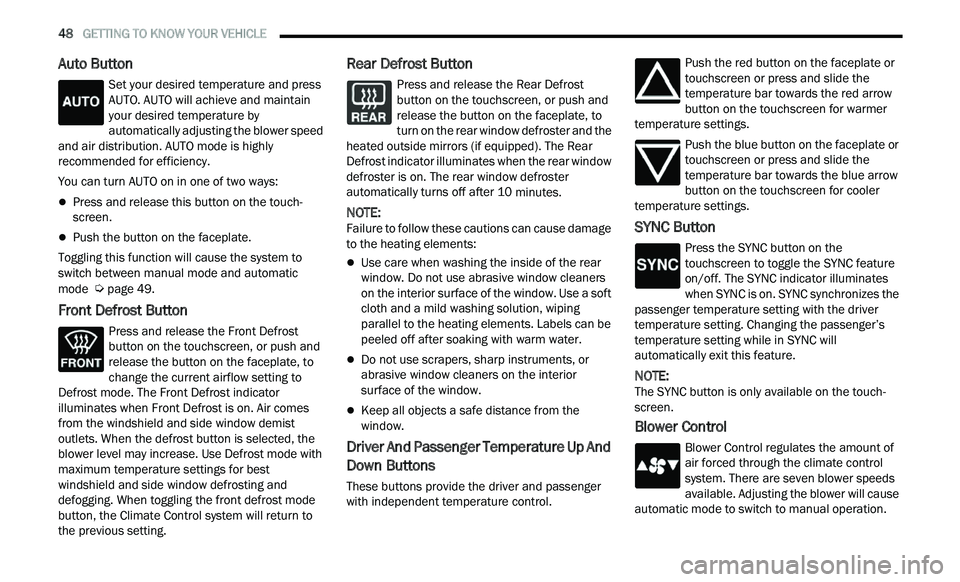
Auto Button
Set your desired temperature and press
AUTO. AUTO will achieve and maintain
you
r desired temperature by
automatically adjusting the blower speed
and air distribution. AUTO mode is highly
recommended for efficiency.
You can turn AUTO on in one of two ways:
Press and release this button on the touch -
screen.
Push the button on the faceplate.
Toggling this function will cause the system to
s w
itch between manual mode and automatic
mode
Ú page 49.
Front Defrost Button
Press and release the Front Defrost
button on the touchscreen, or push and
re
lease the button on the faceplate, to
change the current airflow setting to
Defrost mode. The Front Defrost indicator
illuminates when Front Defrost is on. Air comes
from the windshield and side window demist
outlets. When the defrost button is selected, the
blower level may increase. Use Defrost mode with
maximum temperature settings for best
windshield and side window defrosting and
defogging. When toggling the front defrost mode
button, the Climate Control system will return to
the previous setting.
Rear Defrost Button
Press and release the Rear Defrost
button on the touchscreen, or push and
r e
lease the button on the faceplate, to
turn on the rear window defroster and the
heated outside mirrors (if equipped). The Rear
Defrost indicator illuminates when the rear window
defroster is on. The rear window defroster
automatically turns off after 10 minutes.
NOTE:
Failure to follow these cautions can cause damage
t o
the heating elements:
Use care when washing the inside of the rear
window. Do not use abrasive window cleaners
on the interior surface of the window. Use a soft
cloth and a mild washing solution, wiping
parallel to the heating elements. Labels can be
peeled off after soaking with warm water.
Do not use scrapers, sharp instruments, or
abrasive window cleaners on the interior
surface of the window.
Keep all objects a safe distance from the
window.
Driver And Passenger Temperature Up And
Down Buttons
These buttons provide the driver and passenger
with independent temperature control. Push the red button on the faceplate or
touchscreen or press and slide the
t
e
mperature bar towards the red arrow
button on the touchscreen for warmer
temperature settings.
Push the blue button on the faceplate or
touchscreen or press and slide the
te
mperature bar towards the blue arrow
button on the touchscreen for cooler
temperature settings.
SYNC Button
Press the SYNC button on the
touchscreen to toggle the SYNC feature
o n
/off. The SYNC indicator illuminates
when SYNC is on. SYNC synchronizes the
passenger temperature setting with the driver
temperature setting. Changing the passenger’s
temperature setting while in SYNC will
automatically exit this feature.
NOTE:
The SYNC button is only available on the touch-
screen.
Blower Control
Blower Control regulates the amount of
air forced through the climate control
s y
stem. There are seven blower speeds
available. Adjusting the blower will cause
automatic mode to switch to manual operation.
Page 73 of 268

GETTING TO KNOW YOUR INSTRUMENT PANEL 71
NOTE:
The charging system is independent from load
reduction. The charging system performs a diag
-
nostic on the charging system continuously.
If the Battery Charge Warning Light is on it may
indicate a problem with the charging system
Ú page 73.
The electrical loads that may be switched off (if
e q
uipped), and vehicle functions which can be
affected by load reduction:
Heated Seat/Vented Seats/Heated Wheel —
If Equipped
Heated/Cooled Cup Holders — If Equipped
Rear Defroster And Heated Mirrors
HVAC System
115 Volts AC Power Inverter System
Audio and Telematics System
Loss of the battery charge may indicate one or
m or
e of the following conditions:
The charging system cannot deliver enough
electrical power to the vehicle system because
the electrical loads are larger than the capability
of the charging system. The charging system is
still functioning properly.
Turning on all possible vehicle electrical loads
(e.g. HVAC to max settings, exterior and interior
lights, overloaded power outlets +12 Volts, 115 Volts AC, USB ports) during certain driving
c
on
ditions (city driving, towing, frequent stop -
ping).
Installing options like additional lights, upfitter
electrical accessories, audio systems, alarms
and similar devices.
Unusual driving cycles (short trips separated by
long parking periods).
The vehicle was parked for an extended period
of time (weeks, months).
The battery was recently replaced and was not
charged completely.
The battery was discharged by an electrical load
left on when the vehicle was parked.
The battery was used for an extended period
with the engine not running to supply radio,
lights, chargers, +12 Volt portable appliances
like vacuum cleaners, game consoles and
similar devices.
What to do when an electrical load reduction
a c
tion message is present (“Battery Saver On” or
“Battery Saver Mode”)
During a trip:
Reduce power to unnecessary loads if possible:
Turn off redundant lights (interior or exte -
rior)
Check what may be plugged in to power
outlets +12 Volts, 115 Volts AC, USB ports
Check HVAC settings (blower, temperature)
Check the audio settings (volume)
After a trip:
Check if any aftermarket equipment was
installed (additional lights, upfitter electrical
accessories, audio systems, alarms) and review
specifications if any (load and Ignition Off Draw
currents).
Evaluate the latest driving cycles (distance,
driving time and parking time).
The vehicle should have service performed if
the message is still present during consecutive
trips and the evaluation of the vehicle and
driving pattern did not help to identify the cause.
PROGRAMMABLE FEATURES
The instrument cluster display can be used to view
or change the following settings. Push the up
or
down arrow button to scroll through the main
menus, then push the ri
ght arrow button to
scroll through the submenus of each menu item.
P u
sh the left arrow button to scroll back to a
previous menu or submenu.
WARNING LIGHTS AND MESSAGES
The warning/indicator lights will illuminate in the
instrument panel together with a dedicated
message and/or acoustic signal when applicable.
These indications are indicative and precautionary
3
Page 83 of 268

81
(Continued)
STARTING AND OPERATING
STARTING THE ENGINE
Before starting your vehicle, adjust your seat,
adjust the inside and outside mirrors, fasten your
seat belt, and if present, instruct all other
occupants to buckle their seat belts.
AUTOMATIC TRANSMISSION
The gear selector must be in the PARK position
before you can start the engine. Apply the brakes
before shifting into any driving gear.
KEYLESS ENTER ‘N GO™ — IGNITION
This feature allows the driver to operate the
ignition switch with the push of a button, as long as
the Remote Start/Keyless Enter ‘n Go™ key fob is
in the passenger compartment.
NORMAL STARTING
To Turn On The Engine Using The ENGINE START/
STOP Button
1. The transmission must be in PARK.
2
. P ress and hold the brake pedal while pushing
t
he ENGINE START/STOP button once.
3. The system takes over and attempts to start t
he vehicle. If the vehicle fails to start, the
starter will disengage automatically after
10 seconds.
4. I f you wish to stop the cranking of the engine
p
rior to the engine starting, push the ENGINE
START/STOP button again.
NOTE:
Normal starting of either a cold or a warm engine is
ob t
ained without pumping or pressing the accel -
erator pedal.
WARNING!
When exiting the vehicle, always make sure
the ignition is in OFF mode, remove the key
fob from the vehicle and lock the vehicle.
Never leave children alone in a vehicle, or with
access to an unlocked vehicle. Leaving chil -
dren in a vehicle unattended is dangerous for
a
number of reasons. A child or others could
be seriously or fatally injured. Children should
be warned not to touch the parking brake,
brake pedal or the transmission gear selector.
Do not leave the key fob in or near the vehicle
(or in a location accessible to children), and do
not leave the ignition (of a vehicle equipped
with Keyless Enter ‘n Go™) in the ACC or ON/
RUN mode. A child could operate power
windows, other controls, or move the vehicle.
Do not leave children or animals inside parked
vehicles in hot weather. Interior heat build-up
may cause serious injury or death.
CAUTION!
Shift into or out of PARK or REVERSE only after
the vehicle has come to a complete stop.
Do not shift between PARK, REVERSE,
NEUTRAL, or DRIVE when the engine is above
idle speed.
Before shifting into any gear, make sure your
foot is firmly pressing the brake pedal.
WARNING!
4
Page 102 of 268

100 STARTING AND OPERATING
If the sensor or front end of the vehicle is
damaged due to a collision, see an authorized
dealer for service.
Do not attach or install any accessories near the
sensor, including transparent material or after -
market grilles. Doing so could cause an ACC
s y
stem failure or malfunction.
When the condition that deactivated the system is
no
longer present, the system will return to the
“Adaptive Cruise Control Off” state and will resume
function by simply reactivating it.
NOTE:
If the “ACC/FCW Unavailable Wipe Front Radar
Sensor” message occurs frequently (e.g. more
than once on every trip) without any snow, rain,
mud, or other obstruction, have the radar
sensor realigned at an authorized dealer.
Installing a snow plow, front-end protector, an
aftermarket grille or modifying the grille is not
recommended. Doing so may block the sensor
and inhibit ACC/FCW operation.
“CLEAN FRONT WINDSHIELD” WARNING
The “ACC/FCW Limited Functionality Clean Front
Windshield” warning will display and also a chime
will indicate when conditions temporarily limit
system performance. This most often occurs at
times of poor visibility, such as in snow or heavy
rain and fog. The ACC system may also become temporarily blinded due to obstructions, such as
mud, dirt, or ice on windshield and fog on the
inside of glass. In these cases, the instrument
cluster display will display “ACC/FCW Limited
Functionality Clean Front Windshield” and the
system will have degraded performance.
This message can sometimes be displayed while
d
r
iving in adverse weather conditions. The ACC/
FCW system will recover after the vehicle has left
these areas. Under rare conditions, when the
camera is not tracking any vehicles or objects in its
path this warning may temporarily occur.
If weather conditions are not a factor, the driver
s h
ould examine the windshield and the camera
located on the back side of the inside rearview
mirror. They may require cleaning or removal of an
obstruction.
When the condition that created limited
f u
nctionality is no longer present, the system will
return to full functionality.
NOTE:
If the “ACC/FCW Limited Functionality Clean Front
W i
ndshield” message occurs frequently (e.g. more
than once on every trip) without any snow, rain,
mud, or other obstruction, have the windshield and
forward facing camera inspected at an authorized
dealer.
SERVICE ACC/FCW WARNING
If the system turns off, and the instrument cluster
displays “ACC/FCW Unavailable Service Required”
or “Cruise/FCW Unavailable Service Required”,
there may be an internal system fault or a
temporary malfunction that limits ACC
functionality. Although the vehicle is still drivable
under normal conditions, ACC will be temporarily
unavailable. If this occurs, try activating ACC again
later, following an ignition cycle. If the problem
persists, see an authorized dealer.
Precautions While Driving With ACC
In certain driving situations, ACC may have
detection issues. In these cases, ACC may brake
late or unexpectedly. The driver needs to stay alert
and may need to intervene. The following are
examples of these types of situations:
TOWING A TRAILER
Towing a trailer is not recommended when using
ACC.
Page 130 of 268

128 MULTIMEDIA
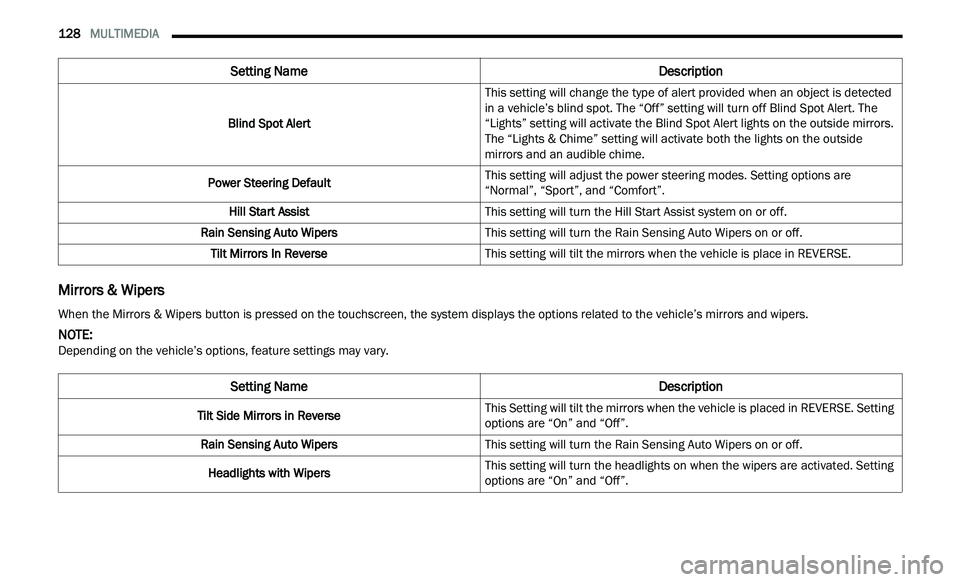
Mirrors & Wipers
Blind Spot Alert This setting will change the type of alert provided when an object is detected
in
a vehicle’s blind spot. The “Off” setting will turn off Blind Spot Alert. The
“Lights” setting will activate the Blind Spot Alert lights on the outside mirrors.
The “Lights & Chime” setting will activate both the lights on the outside
mirrors and an audible chime.
Power Steering Default This setting will adjust the power steering modes. Setting options are
“N
ormal”, “Sport”, and “Comfort”.
Hill Start Assist This setting will turn the Hill Start Assist system on or off.
Rain Sensing Auto Wipers This setting will turn the Rain Sensing Auto Wipers on or off.
Tilt Mirrors In Reverse This setting will tilt the mirrors when the vehicle is place in REVERSE.
Setting Name Description
When the Mirrors & Wipers button is pressed on the touchscreen, the system displays the options related to the vehicle’s mirrors and wipers.
NOTE:
Depending on the vehicle’s options, feature settings may vary.
Setting Name Description
Tilt Side Mirrors in ReverseThis Setting will tilt the mirrors when the vehicle is placed in REVERSE. Setting
op
t
ions are “On” and “Off”.
Rain Sensing Auto Wipers This setting will turn the Rain Sensing Auto Wipers on or off.
Headlights with Wipers This setting will turn the headlights on when the wipers are activated. Setting
op
t
ions are “On” and “Off”.
Page 144 of 268

142 SAFETY
Towing With HSA
HSA will also provide assistance to mitigate roll
back while towing a trailer.
Rain Brake Support (RBS)
RBS may improve braking performance in wet
conditions. It will periodically apply a small amount
of brake pressure to remove any water buildup on
the front brake rotors. It functions when the windshield wipers are in LO or HI speed. When RBS
is active, there is no notification to the driver and
no driver interaction is required.
Ready Alert Braking (RAB)
RAB may reduce the time required to reach full
braking during emergency braking situations. It
anticipates when an emergency braking situation
may occur by monitoring how fast the throttle is
released by the driver. The Electronic Brake
Controller (EBC) will prepare the brake system for
a panic stop.
Traction Control System (TCS)
TCS monitors the amount of wheel spin of each of
the driven wheels. If wheel spin is detected, the
TCS may apply brake pressure to the spinning
wheel(s) and/or reduce engine power to provide
enhanced acceleration and stability. A feature of
the TCS, Brake Limited Differential (BLD) functions
similarly to a limited slip differential and controls
the wheel spin across a driven axle. If one wheel on
a driven axle is spinning faster than the other, the
system will apply the brake of the spinning wheel.
This will allow more engine torque to be applied to
the wheel that is not spinning. BLD may remain
enabled even if TCS and Electronic Stability Control
(ESC) are in reduced modes.
AUXILIARY DRIVING SYSTEMS
BLIND SPOT MONITORING (BSM) —
I
F EQUIPPED
The BSM system uses two radar sensors, located
inside the rear fascia/bumper, to detect highway
licensable vehicles (automobiles, trucks,
motorcycles, etc.) that enter the blind spot zones
from the rear/front/side of the vehicle.
Rear Detection Zones
When the vehicle is started, the BSM Warning Light
wi
ll momentarily illuminate in both outside
rearview mirrors to let the driver know that the
system is operational. The BSM system sensors
operate when the vehicle is in any forward gear or
REVERSE.
WARNING!
If you use a trailer brake controller with your
trailer, the trailer brakes may be activated and
deactivated with the brake switch. If so, there
may not be enough brake pressure to hold
both the vehicle and the trailer on a hill when
the brake pedal is released. In order to avoid
rolling down an incline while resuming accel -
eration, manually activate the trailer brake or
a p
ply more vehicle brake pressure prior to
releasing the brake pedal.
HSA is not a parking brake. Always apply the
parking brake fully when exiting your vehicle.
Also, be certain to place the transmission in
PARK.
Failure to follow these warnings can result in a
collision or serious personal injury.
Page 145 of 268

SAFETY 143
BSM Warning Light
The BSM detection zone covers approximately one
la
ne width on both sides of the vehicle 12 ft
( 3
.8 m). The zone length starts at the outside
r e
arview mirror and extends approximately 10 ft
( 3
m) beyond the rear fascia/bumper of the
v e
hicle. The BSM system monitors the detection
zones on both sides of the vehicle when the vehicle
speed reaches approximately 6 mph (10 km/h) or
h i
gher and will alert the driver of vehicles in these
areas.
NOTE:
The BSM system DOES NOT alert the driver
about rapidly approaching vehicles that are
outside the detection zones.
The BSM system detection zone DOES NOT
change if your vehicle is towing a trailer. There -
fore, visually verify the adjacent lane is clear for
b ot
h your vehicle and trailer before making a lane change. If the trailer or other object (i.e.,
bicycle, sports equipment) extends beyond the
side of your vehicle, this may result in the BSM
warning light randomly alerting on the trailer or
even remaining illuminated the entire time the
vehicle is in a forward gear
Ú page 122.
The Blind Spot Monitoring (BSM) system may
experience drop outs (blinking on and off) of the
side mirror warning indicator lamps when a
motorcycle or any small object remains at the
side of the vehicle for extended periods of time
(more than a couple of seconds).
The BSM system can become blocked if snow, ice,
mu
d, or other road contaminations accumulate on
the rear fascia/bumper where the radar sensors
are located. The system may also detect blockage
if the vehicle is operated in areas with extremely
low radar returns such as a desert or parallel to a
large elevation drop. If blockage is detected, a
“Blind Spot Temporarily Unavailable, Wipe Rear
Corners” message will display in the cluster, both
mirror lights will illuminate, and BSM and RCP
alerts will not occur. This is normal operation. The
system will automatically recover and resume
function when the condition clears. To minimize
system blockage, do not block the area of the rear
fascia/bumper where the radar sensors are
located with foreign objects (bumper stickers,
bicycle racks, etc.) and keep it clear of road
contaminations.
Sensor Location (Driver Side Shown)
The BSM system notifies the driver of objects in the
d e
tection zones by illuminating the BSM warning
light located in the outside mirrors in addition to
sounding an audible (chime) alert and reducing the
radio volume if the corresponding turn signal is
activated
Ú page 146.
The BSM system monitors the detection zone from
t h
ree different entry points (side, rear, front) while
driving to see if an alert is necessary. The BSM
system will issue an alert during these types of
zone entries.
6
Page 147 of 268

SAFETY 145
The BSM system will not alert you of objects that
are traveling in the opposite direction of the vehicle
in adjacent lanes
Ú page 254.
Opposing Traffic
Rear Cross Path (RCP) Detection — If
Equipped
RCP is intended to aid the driver when backing out
of parking spaces where their vision of oncoming
vehicles may be blocked. Proceed slowly and
cautiously out of the parking space until the rear
end of the vehicle is exposed. The RCP system will
then have a clear view of the cross traffic and if an
oncoming vehicle is detected, alert the driver.
RCP Detection Zones
RCP monitors the rear detection zones on both
si
des of the vehicle, for objects that are moving
toward the side of the vehicle with a minimum
speed of approximately 3 mph (5 km/h), to objects
m ov
ing a maximum of approximately 20 mph
( 3
2 km/h), such as in parking lot situations. When RCP is on and the vehicle is in REVERSE, the
d
r
iver is alerted using both the visual and audible
alarms, including reducing the radio volume.
NOTE:
In a parking lot situation, oncoming vehicles can be
b l
ocked by vehicles parked on either side. If the
sensors are blocked by other structures or
vehicles, the system will not be able to alert the
driver.
WARNING!
The Blind Spot Monitoring system is only an aid
to help detect objects in the blind spot zones.
The BSM system is not designed to detect
pedestrians, bicyclists, or animals. Even if your
vehicle is equipped with the BSM system, always
check your vehicle’s mirrors, glance over your
shoulder, and use your turn signal before
changing lanes. Failure to do so can result in
serious injury or death.
WARNING!
Rear Cross Path Detection (RCP) is not a backup
aid system. It is intended to be used to help a
driver detect an oncoming vehicle in a parking
lot situation. Drivers must be careful when
backing up, even when using RCP. Always check
carefully behind your vehicle, look behind you,
and be sure to check for pedestrians, animals,
other vehicles, obstructions, and blind spots
before backing up. Failure to do so can result in
serious injury or death.
6