Page 215 of 268

SERVICING AND MAINTENANCE 213
Fluid Level Check
The fluid level is preset at the factory and does not
require adjustment under normal operating
conditions. Routine fluid level checks are not
required; therefore the transmission has no
dipstick. An authorized dealer can check your
transmission fluid level using special service tools.
If you notice fluid leakage or transmission
malfunction, visit an authorized dealer
immediately to have the transmission fluid level
checked. Operating the vehicle with an improper
fluid level can cause severe transmission damage.
Fluid And Filter Changes
Under normal operating conditions, the fluid
installed at the factory will provide satisfactory
lubrication for the life of the vehicle.
Routine fluid and filter changes are not required.
How e
ver, change the fluid and filter if the fluid
becomes contaminated (with water, etc.), or if the
transmission is disassembled for any reason.
Selection Of Lubricant
It is important to use the proper transmission fluid
to ensure optimum transmission performance and
life. Use only the manufacturer's specified
transmission fluid
Ú page 250. It is important to
maintain the transmission fluid at the correct level
u s
ing the recommended fluid.
NOTE:
No chemical flushes should be used in any trans -
mission; only the approved lubricant should be
u s
ed.
ALL WHEEL DRIVE (AWD) —
I
F EQUIPPED
The All Wheel Drive system consists of a transfer
case and front differential. The exterior surface of
these components should be inspected for
evidence of fluid leaks. Confirmed leaks should be
repaired as soon as possible.
The transfer case fluid fill/inspection plug is
l oc
ated in the middle of the rear housing. To
inspect the transfer case fluid level, remove the
fill/inspection plug. The fluid level should be even
with the bottom of the hole. Use this plug to add
fluid as required.
The front differential fill plug is located on the outer
cov
er near the half shaft attachment. To inspect
the differential fluid level, remove the fill plug. The
fluid level should be even with or slightly below the
bottom of the hole.
Fluid Changes
For the proper maintenance intervals Ú page 195.
REAR AXLE
For normal service, periodic fluid level checks are
not required. When the vehicle is serviced for other
reasons the exterior surfaces of the axle assembly
should be inspected. If gear oil leakage is
suspected inspect the fluid level
Ú page 250.
CAUTION!
Do not use chemical flushes in your
transmission as the chemicals can damage your
transmission components. Such damage is not
covered by the New Vehicle Limited Warranty.
CAUTION!
If a transmission fluid leak occurs, visit an
authorized dealer immediately. Severe
transmission damage may occur. An authorized
dealer has the proper tools to adjust the fluid
level accurately.CAUTION!
Using a transmission fluid other than the
manufacturer’s recommended fluid may cause
deterioration in transmission shift quality and/or
torque converter shudder
Ú page 250.
8
Page 220 of 268
218 SERVICING AND MAINTENANCE
Cavity Cartridge Fuse Mini-Fuse Description
* If Equipped
F02 60 Amp Yellow –Front PDC Feed #1
F03 ––Spare
F04 60 Amp Yellow –Front PDC Feed #2
F05 30 Amp Pink
20 Amp Blue – Police –
Sunroof/Dome Lamp – Police
F06 40 Amp Green –Exterior Lighting #1
F07 40 Amp Green –Exterior Lighting #2
F08 30 Amp Pink –Interior Lighting
F09 40 Amp Green –Power Locks
F10 30 Amp Pink –Driver Door Control Module
F11 30 Amp Pink –Passenger Door Control Module
F12 –20 Amp YellowCigar Lighter/IP APO/RR USB (Selectable Fuse) *
F15 40 Amp Green –HVAC Blower
F16 20 Amp Blue –Left Spot Lamp – Police
F17 20 Amp Blue –Right Spot Lamp – Police
F18 30 Amp Pink –VISM Mod (Police)
F19 ––Spare
F20 ––Spare
F21 30 Amp Pink –Fuel Pump (Non 6.2L SRT)
F22 –5 Amp TanCyber Gateway Module
Page 221 of 268
SERVICING AND MAINTENANCE 219
F23 –10 Amp RedFuel Door * / Diagnostic Port
F24 –10 Amp RedIntegrated Center Stack
F25 –10 Amp RedTire Pressure Monitor System
F26 –15 Amp BlueTrans Mod (Charger Non- Police/300)
F27 –25 Amp ClearAmplifier *
F31 –25 Amp BreakerPower Seats *
F32 –15 Amp BlueHVAC Module/Cluster
F33 –15 Amp BlueIGN SW/Wireless Mod/Steer Clmn Lock Mod/Remote
S
t
art *
F34 –10 Amp RedSteering Column Module/Clock (300)
F35 –5 Amp TanBattery Sensor
F36 –15 Amp BlueActive Exhaust Valve *
F37 –20 Amp YellowRadio
F38 –20 Amp YellowMedia Hub / Console APO
F42 30 Amp Pink –Rear Defrost
F43 –20 Amp YellowRear Heated Seats * / Heated Steering Wheel *
F44 –10 Amp RedPark Assist / Blind Spot / Rear View Camera
F45 –15 Amp BlueCluster / Rearview Mirror / Lane Departure
F46 ––Spare
F47 –10 Amp RedAdaptive Front Lighting / Day Time Running Lamps *
Cavity Cartridge Fuse Mini-Fuse Description
* If Equipped
8
Page 222 of 268
220 SERVICING AND MAINTENANCE
F49 ––Spare
F50 ––Spare
F51 –20 Amp YellowFront Heated / Vented Seats *
F52 –10 Amp RedHeated/Cooled Cup Holders/Rear Heated Seat
Sw
itches *
F53 –10 Amp RedHVAC Module/In Vehicle Temperature Sensor
F54 ––Spare
F55 ––Spare
F56 ––Spare
F57 ––Spare
F58 –10 Amp RedAirbag Module
F59 –20 Amp YellowAdjustable Pedals – Police
F60 ––Spare
F61 ––Spare
F62 ––Spare
F63 ––Spare
F64 –25 Amp BreakerRear Windows (Charger/300)
F65 –10 Amp RedAirbag Module
F66 ––Spare
F67 –10 Amp RedRain and Light Sensor / Sunroof / Inside RearView
M
i
rror / Police Run Acc Relay
Cavity Cartridge Fuse Mini-Fuse Description
* If Equipped
Page 223 of 268
SERVICING AND MAINTENANCE 221
BULB REPLACEMENT
Replacement Bulbs
All of the interior bulbs are glass wedge base or glass cartridge types. Aluminum base bulbs are not approved and should not be used for replacement. F68
–10 Amp RedRear USB Timer / Rear Sunshade *
F69 ––Spare
F70 ––Spare
Cavity Cartridge Fuse Mini-Fuse Description
* If Equipped
Interior Bulbs
Bulb Name Bulb Number
Rear Courtesy/Reading Lamps W5W
Rear Compartment (Trunk) Lamp 562
Overhead Console Reading Lamps 578
Visor Vanity Lamps A6220
Glove Compartment Lamp – If Equipped 194
Door Courtesy 562
Shift Indicator Lamp JKLE14140
Optional Door Map Pocket/Cupholder LED (Serviced at an authorized dealer)
For lighted switches, see an authorized dealer for replacement instructions.
8
Page 224 of 268

222 SERVICING AND MAINTENANCE
Replacing Exterior Bulbs
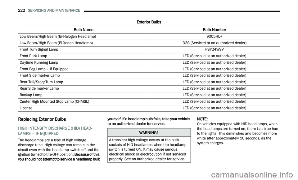
HIGH INTENSITY DISCHARGE (HID) HEAD -
LAMPS — IF EQUIPPED
The headlamps are a type of high voltage
discharge tube. High voltage can remain in the
circuit even with the headlamp switch off and the
ignition turned to the OFF position. Because of this,
you should not attempt to service a headlamp bulb yourself. If a headlamp bulb fails, take your vehicle
to an authorized dealer for service.
NOTE:
On vehicles equipped with HID headlamps, when
t h
e headlamps are turned on, there is a blue hue
to the lights. This diminishes and becomes more
white after approximately 10 seconds, as the
system charges.
Exterior Bulbs
Bulb Name Bulb Number
Low Beam/High Beam (Bi-Halogen Headlamp) 9005HL+
Low Beam/High Beam (Bi-Xenon Headlamp) D3S (Serviced at an authorized dealer)
Front Turn Signal Lamp PSY24WSV
Front Park Lamp LED (Serviced at an authorized dealer)
Daytime Running Lamp LED (Serviced at an authorized dealer)
Front Fog Lamp – If Equipped LED (Serviced at an authorized dealer)
Front Side marker Lamp LED (Serviced at an authorized dealer)
Rear Tail/Stop/Turn Lamp LED (Serviced at an authorized dealer)
Rear Side marker Lamp LED (Serviced at an authorized dealer)
Backup Lamp LED (Serviced at an authorized dealer)
Center High Mounted Stop Lamp (CHMSL) LED (Serviced at an authorized dealer)
License LED (Serviced at an authorized dealer)
WARNING!
A transient high voltage occurs at the bulb
sockets of HID headlamps when the headlamp
switch is turned ON. It may cause serious
electrical shock or electrocution if not serviced
properly. See an authorized dealer for service.
Page 227 of 268

SERVICING AND MAINTENANCE 225
TIRES
TIRE SAFETY INFORMATION
Tire safety information will cover aspects of the
following information: Tire Markings, Tire
Identification Numbers, Tire Terminology and
Definitions, Tire Pressures, and Tire Loading.
Tire Markings
Tire Markings
NOTE:
P (Passenger) — Metric tire sizing is based on US
design standards. P-Metric tires have the letter
“P” molded into the sidewall preceding the size
designation. Example: P215/65R15 95H.
European — Metric tire sizing is based on Euro -
pean design standards. Tires designed to this
s t
andard have the tire size molded into the side -
wall beginning with the section width. The letter
"P
" is absent from this tire size designation.
Example: 215/65R15 96H.
LT (Light Truck) — Metric tire sizing is based on
US design standards. The size designation for
LT-Metric tires is the same as for P-Metric tires
except for the letters “LT” that are molded into
the sidewall preceding the size designation.
Example: LT235/85R16.
Temporary spare tires are designed for tempo -
rary emergency use only. Temporary high pres -
sure compact spare tires have the letter “T” or
“ S
” molded into the sidewall preceding the size
designation. Example: T145/80D18 103M.
High flotation tire sizing is based on US design
standards and it begins with the tire diameter
molded into the sidewall. Example: 31x10.5
R15 LT.
1 — US DOT Safety Standards Code (TIN)
2 — Size Designation
3 — Service Description
4 — Maximum Load
5 — Maximum Pressure
6 — Treadwear, Traction and
Temperature Grades
8
Page 228 of 268

226 SERVICING AND MAINTENANCE
TIRE SIZING CHART
EXAMPLE:
Example Size Designation: P215/65R15XL 95H, 215/65R15 96H, LT235/85R16C, T145/80D18 103M, 31x10.5 R15 LT
P = Passenger car tire size based on US design standards, or
"....blank...." =
Passenger car tire based on European design standards, or
LT = Light truck tire based on US design standards, or
T
or S = Temporary spare tire or
3
1 = Overall diameter in inches (in)
2
15, 235, 145 =
Section width in millimeters (mm)
65, 85, 80 = Aspect ratio in percent (%)
Ratio of section height to section width of tire, or
10.5 = Section width in inches (in)
R
= Construction code
"R" means radial construction, or
"D" means diagonal or bias construction
15, 16, 18 = Rim diameter in inches (in)
S
ervice Description:
95 = Load Index
A numerical code associated with the maximum load a tire can carry
H = Speed Symbol
A symbol indicating the range of speeds at which a tire can carry a load corresponding to its load index under certain operating conditions
The maximum speed corresponding to the speed symbol should only be achieved under specified operating conditions (i.e., tire pressure, vehicle loading,
road conditions, and posted speed limits)