2021 CHRYSLER 300 wheel torque
[x] Cancel search: wheel torquePage 8 of 268

6
DEPARTMENT OF TRANSPORTATION
UNIFORM TIRE QUALITY GRADES .. .................. 241
Treadwear ...................................................... 241
T raction Grades . . ........................................... 241
Temperature Grades . . ................................... 241
VEHICLE STORAGE . . ............................................ 242
BODYWORK .. ........................................................ 242
Protection From Atmospheric Agents ..
........ 242
Body And Underbody Maintenance. . ............ 242
Preserving The Bodywork . . ........................... 242
INTERIORS . . ......................................................... 243
Seats And Fabric Parts.. ................................ 243
Plastic And Coated Parts . . ............................ 243
Leather Surfaces . . ......................................... 244
Glass Surfaces . . ............................................ 244
TECHNICAL SPECIFICATIONS
VEHICLE IDENTIFICATION NUMBER (VIN)......... 245
BRAKE SYSTEM .. ................................................ 245
WHEEL AND TIRE TORQUE SPECIFICATIONS .. 245
Torque Specifications .. ................................. 245 FUEL REQUIREMENTS .
.
...................................... 246
3.6L Engine .. ................................................. 246
5.7L Engine . . ................................................. 246
Reformulated Gasoline . . ............................... 246
Materials Added To Fuel . . ............................. 246
Gasoline/Oxygenate Blends . . ....................... 247
Do Not Use E-85 In Non-Flex Fuel
Vehicles. ......................................................... 247
C
NG And LP Fuel System Modifications . . .... 247
Methylcyclopentadienyl Manganese
Tricarbonyl (MMT) In Gasoline. .
.................... 247
Fuel System Cautions . . ................................. 248
FLUID CAPACITIES . . ............................................ 248
ENGINE FLUIDS AND LUBRICANTS.. ................. 249
CHASSIS FLUIDS AND LUBRICANTS .. .............. 250
CUSTOMER ASSISTANCE
SUGGESTIONS FOR OBTAINING SERVICE
FOR YOUR VEHICLE .. ......................................... 251
Prepare For The Appointment .. .................... 251
Prepare A List . . .............................................. 251
Be Reasonable With Requests. . ................... 251IF YOU NEED ASSISTANCE .
.
.............................. 251
FCA US LLC Customer Center.. ..................... 251
FCA Canada Inc. Customer Center . . ............ 251
Mexico. ........................................................... 251
P uerto Rico And US Virgin Islands . . ............. 252
Customer Assistance For The Hearing Or
Speech Impaired
(TDD/TTY) . ..................................................... 252
S
ervice Contract . . ......................................... 252
WARRANTY INFORMATION . . .............................. 252
MOPAR® PARTS .. ............................................... 253
REPORTING SAFETY DEFECTS .. ........................ 253
In The 50 United States And
Washington, D.C.. .
......................................... 253
In Canada . ..................................................... 253
P
UBLICATION ORDER FORMS . . ........................ 253
GENERAL INFORMATION.. .................................. 254
Page 110 of 268
108 STARTING AND OPERATING
LANESENSE — IF EQUIPPED
LANESENSE OPERATION
The LaneSense system is operational at speeds
above 37 mph (60 km/h) and below 112 mph
( 1
80 km/h). The LaneSense system uses a
f or
ward looking camera to detect lane markings
and measure vehicle position within the lane
boundaries.
When both lane markings are detected and the
dr
iver unintentionally drifts out of the lane (no turn
signal applied), the LaneSense system provides a
haptic warning in the form of torque applied to the
steering wheel to prompt the driver to remain
within the lane boundaries. If the driver
unintentionally drifts out of the lane, the
LaneSense system provides a visual warning
through the instrument cluster display to prompt
the driver to remain within the lane boundaries.
The driver may manually override the haptic
w a
rning by applying torque into the steering wheel
at any time.
When only a single lane marking is detected and
t h
e driver unintentionally drifts across the lane
marking (no turn signal applied), the LaneSense
system provides visual warnings through the
instrument cluster display to prompt the driver to remain within the lane. When only a single lane
marking is detected, a haptic (torque) warning will
not be provided.
NOTE:
When operating conditions have been met, the
La n
eSense system will monitor if the driver’s
hands are on the steering wheel and provide an
audible warning to the driver if removed. The
system will cancel if the driver does not return their
hands to the wheel.
TURNING LANESENSE ON OR OFF
The LaneSense button is located on the
center stack below the Uconnect display.
To turn the LaneSense system on, push the
Lan
eSense button (LED turns off). A “LaneSense
On” message is shown in the instrument cluster
display.
To turn the LaneSense system off, push the
Lan
eSense button once (LED turns on). A
“LaneSense Off” message is shown in the
instrument cluster display.
NOTE:
The LaneSense system will retain the last system
s t
ate, on or off, from the last ignition cycle when
the ignition is changed to the ON/RUN position.
LANESENSE WARNING MESSAGE
The LaneSense system will indicate the current
lane drift condition through the instrument cluster
display.
Premium Instrument Cluster Display
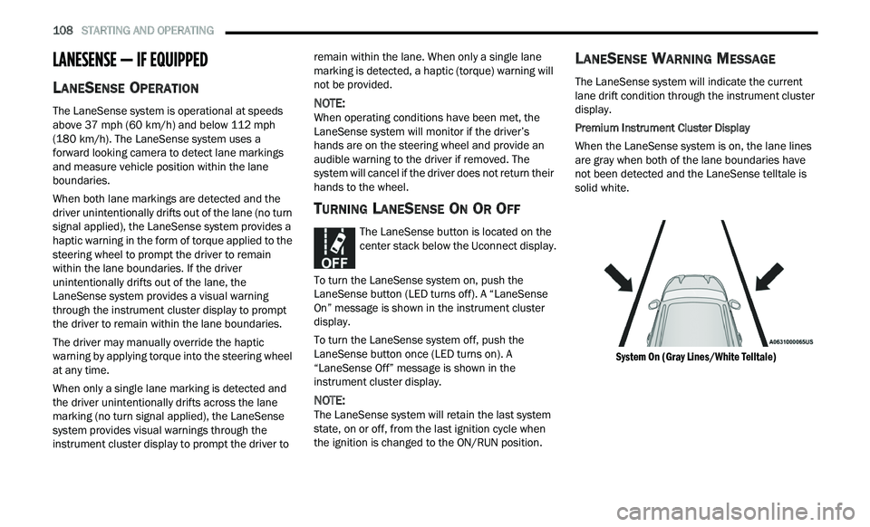
When the LaneSense system is on, the lane lines
a r
e gray when both of the lane boundaries have
not been detected and the LaneSense telltale is
solid white.
System On (Gray Lines/White Telltale)
Page 111 of 268
STARTING AND OPERATING 109
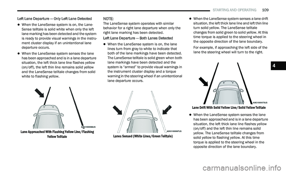
Left Lane Departure — Only Left Lane Detected
When the LaneSense system is on, the Lane-
Sense telltale is solid white when only the left
l a
ne marking has been detected and the system
is ready to provide visual warnings in the instru -
ment cluster display if an unintentional lane
d e
parture occurs.
When the LaneSense system senses the lane
has been approached and is in a lane departure
situation, the left thick lane line flashes yellow
(on/off), the left thin line remains solid yellow
and the LaneSense telltale changes from solid
white to flashing yellow.
Lane Approached With Flashing Yellow Line/Flashing Ye
llow Telltale
NOTE:
The LaneSense system operates with similar
b e
havior for a right lane departure when only the
right lane marking has been detected.
Left Lane Departure — Both Lanes Detected
When the LaneSense system is on, the lane
lines turn from gray to white to indicate that
both of the lane markings have been detected.
The LaneSense telltale is solid green when both
lane markings have been detected and the
system is “armed” to provide visual warnings in
the instrument cluster display and a torque
warning in the steering wheel if an unintentional
lane departure occurs.
Lanes Sensed (White Lines/Green Telltale)
When the LaneSense system senses a lane drift
situation, the left thick lane line and left thin line
turn solid yellow. The LaneSense telltale
changes from solid green to solid yellow. At this
time torque is applied to the steering wheel in
the opposite direction of the lane boundary.
For example, if approaching the left side of the
la
ne the steering wheel will turn to the right.
Lane Drift With Solid Yellow Line/Solid Yellow Telltale
When the LaneSense system senses the lane
has been approached and is in a lane departure
situation, the left thick lane line flashes yellow
(on/off) and the left thin line remains solid
yellow. The LaneSense telltale changes from
solid yellow to flashing yellow. At this time
torque is applied to the steering wheel in the
opposite direction of the lane boundary.
4
Page 112 of 268
110 STARTING AND OPERATING
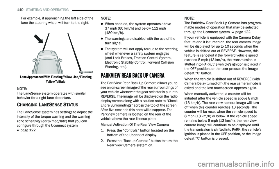
For example, if approaching the left side of the
lane the steering wheel will turn to the right.
Lane Approached With Flashing Yellow Line/Flashing Ye
llow Telltale
NOTE:
The LaneSense system operates with similar
b e
havior for a right lane departure.
CHANGING LANESENSE STATUS
The LaneSense system has settings to adjust the
intensity of the torque warning and the warning
zone sensitivity (early/med/late) that you can
configure through the Uconnect system
Ú page 122.
NOTE:
When enabled, the system operates above
37
mph (60 km/h) and below 112 mph
( 1
80 km/h).
The warnings are disabled with the use of the
turn signal.
The system will not apply torque to the steering
wheel whenever a safety system engages
(Anti-Lock Brakes, Traction Control System,
Electronic Stability Control, Forward Collision
Warning, etc.).
PARKVIEW REAR BACK UP CAMERA
The ParkView Rear Back Up Camera allows you to
see an on-screen image of the rear surroundings of
your vehicle whenever the gear selector is put into
REVERSE. The image will be displayed on the radio
display screen along with a caution note to “Check
Entire Surroundings” across the top of the screen.
After five seconds this note will disappear. The
ParkView camera is located on the rear of the
vehicle above the rear license plate.
Manual Activation Of The Rear View Camera
1. P
ress the “Controls” button located on the
b
ottom of the Uconnect display.
2. Press the “Backup Camera” button to turn the R
ear View Camera system on.
NOTE:
The ParkView Rear Back Up Camera has program -
mable modes of operation that may be selected
t h
rough the Uconnect system Ú page 122.
If your vehicle is equipped with the Camera Delay
f e
ature and it is turned on, the rear camera image
will be displayed for up to 10 seconds when the
vehicle is shifted out of REVERSE. However, this
feature is canceled if the forward vehicle speed
exceeds 8 mph (13 km/h), the transmission is
s h
ifted into PARK, the vehicle's ignition is placed in
the OFF position, or the user presses the image
defeat “X” button.
When the vehicle is shifted out of REVERSE (with
Ca
mera Delay turned off), the rear camera mode is
exited and the last touchscreen appears again.
When manually activated, a counter will be
i n
itiated after the vehicle speed is above 8 mph
( 1
3 km/h). The rear view camera image will turn
of f
when this counter reaches 10 seconds. The
counter will be reset when the vehicle speed is
8 mph (13 km/h) or below. If the vehicle speed
r e
mains below 8 mph (13 km/h), the rear view
c a
mera image will continue to be displayed until
the transmission is shifted into PARK, the vehicle’s
ignition is placed in the OFF position, or the image
defeat “X” button is pressed.
Page 140 of 268
138 SAFETY
Brake Warning Light does not come on when the
ignition is placed in the ON/RUN mode, have the
light repaired as soon as possible.
ELECTRONIC BRAKE CONTROL (EBC)
S
YSTEM
Your vehicle is equipped with an advanced
Electronic Brake Control (EBC) system. This system
includes Anti-Lock Brake System (ABS), Brake
Assist System (BAS), Electronic Brake Force
Distribution (EBD), Electronic Roll Mitigation
(ERM), Electronic Stability Control (ESC), Hill Start
Assist (HSA), and Traction Control System (TCS).
These systems work together to enhance both
vehicle stability and control in various driving
conditions.
Your vehicle may also be equipped with Rain Brake
S u
pport (RBS) and Ready Alert Braking (RAB).
Brake System Warning Light
The red Brake System Warning Light will turn on
when the ignition is placed in the ON/RUN mode
and may stay on for as long as four seconds.
If the Brake System Warning Light remains on or
com
es on while driving, it indicates that the brake
system is not functioning properly and that
immediate service is required. If the Brake System
Warning Light does not come on when the ignition
is placed in the ON/RUN mode, have the light
repaired as soon as possible.
Brake Assist System (BAS)
The BAS is designed to optimize the vehicle’s
braking capability during emergency braking
maneuvers. The system detects an emergency
braking situation by sensing the rate and amount
of brake application and then applies optimum
pressure to the brakes. This can help reduce
braking distances. The BAS complements the
Anti-Lock Brake System (ABS). Applying the brakes
very quickly results in the best BAS assistance. To
receive the benefit of the system, you must apply
continuous braking pressure during the stopping
sequence (do not “pump” the brakes). Do not
reduce brake pedal pressure unless braking is no
longer desired. Once the brake pedal is released,
the BAS is deactivated.
Electronic Brake Force Distribution (EBD)
EBD manages the distribution of the braking
torque between the front and rear axles by limiting
braking pressure to the rear axle. This is done to
prevent overslip of the rear wheels to avoid vehicle
instability, and to prevent the rear axle from
entering the Anti-Lock Brake System (ABS) before
the front axle.
Electronic Roll Mitigation (ERM)
ERM anticipates the potential for wheel lift by
monitoring the driver’s steering wheel input and
the speed of the vehicle. When ERM determines
that the rate of change of the steering wheel angle
and vehicle’s speed are sufficient to potentially
cause wheel lift, it then applies the appropriate
brake and may also reduce engine power to lessen
the chance that wheel lift will occur. ERM can only
reduce the chance of wheel lift occurring during
severe or evasive driving maneuvers; it cannot
prevent wheel lift due to other factors, such as
road conditions, leaving the roadway, striking
objects or other vehicles.
NOTE:
ERM is disabled any time the ESC is in “Full Off”
m od
e (if equipped). See Ú page 139 in this
section for a complete explanation of the available
E S
C modes.
WARNING!
The Brake Assist System (BAS) cannot prevent
the natural laws of physics from acting on the
vehicle, nor can it increase the traction afforded
by prevailing road conditions. BAS cannot
prevent collisions, including those resulting from
excessive speed in turns, driving on very slippery
surfaces, or hydroplaning. The capabilities of a
BAS-equipped vehicle must never be exploited in
a reckless or dangerous manner, which could
jeopardize the user's safety or the safety of
others.
Page 142 of 268
140 SAFETY
(Continued)
Partial Off
This mode may be useful if the vehicle becomes
st
uck. This mode may modify TCS and ESC
thresholds for activation, which allows for more
wheel spin than normally allowed.
To enter the “Partial Off” mode, momentarily push
th
e ESC OFF button and the ESC OFF Indicator
Light will illuminate. To turn the ESC on again,
momentarily push the ESC OFF button and the ESC
OFF Indicator Light will turn off.
NOTE:
For vehicles with multiple partial ESC modes,
the push and release of the button will toggle
the ESC modes. Multiple attempts may be
required to return to "ESC On" mode.
Trailer Sway Control (TSC) is disabled when the
ESC system is in the “Partial Off” mode.
If Equipped — "ESC Sport" and "ESC Track" are
ESC “Partial Off” mode(s).
Full Off – If Equipped
This mode is intended for off-highway or off-road
u s
e only and should not be used on any public
roadways. In this mode, TCS and ESC features are
turned off. To enter the “Full Off” mode, push and
hold the ESC OFF button for five seconds while the
vehicle is stopped with the engine running. After
five seconds, a chime will sound, the ESC OFF
Indicator Light will illuminate, and the “ESC OFF”
message will display in the instrument cluster. To
turn ESC on again, momentarily push the ESC OFF
button.
ESC Activation/Malfunction Indicator Light
And ESC OFF Indicator Light
The ESC Activation/Malfunction Indicator
Light in the instrument cluster will come
o n
when the ignition is placed in the ON
position. It should go out with the engine
running. If the ESC Activation/Malfunction
Indicator Light comes on continuously with the
engine running, a malfunction has been detected
in the ESC system. If this light remains on after
several ignition cycles, and the vehicle has been
driven several miles (kilometers) at speeds greater
WARNING!
When in “Partial Off” mode, the TCS functionality
of ESC (except for the limited slip feature
described in the TCS section) has been disabled
and the ESC OFF Indicator Light will be
illuminated. When in “Partial Off” mode, the
engine power reduction feature of TCS is
disabled, and the enhanced vehicle stability
offered by the ESC system is reduced.
WARNING!
In the ESC “Full Off” mode, the engine torque
reduction and stability features are disabled.
Therefore, enhanced vehicle stability offered
by the ESC system is unavailable. In an emer -
gency evasive maneuver, the ESC system will
n ot
engage to assist in maintaining stability.
ESC “Full Off” mode is intended for
off-highway or off-road use only.
With the ESC switched off, the enhanced
vehicle stability offered by ESC is unavailable.
In an emergency evasive maneuver, the ESC
system will not engage to assist in maintaining
stability. ESC “Full Off” mode is only intended
for off-highway or off-road use.
The Electronic Stability Control (ESC) cannot
prevent the natural laws of physics from
acting on the vehicle, nor can it increase the
traction afforded by prevailing road condi -
tions. ESC cannot prevent all accidents,
i n
cluding those resulting from excessive
speed in turns, driving on very slippery
surfaces, or hydroplaning. ESC also cannot
prevent collisions.
WARNING!
Page 144 of 268

142 SAFETY
Towing With HSA
HSA will also provide assistance to mitigate roll
back while towing a trailer.
Rain Brake Support (RBS)
RBS may improve braking performance in wet
conditions. It will periodically apply a small amount
of brake pressure to remove any water buildup on
the front brake rotors. It functions when the windshield wipers are in LO or HI speed. When RBS
is active, there is no notification to the driver and
no driver interaction is required.
Ready Alert Braking (RAB)
RAB may reduce the time required to reach full
braking during emergency braking situations. It
anticipates when an emergency braking situation
may occur by monitoring how fast the throttle is
released by the driver. The Electronic Brake
Controller (EBC) will prepare the brake system for
a panic stop.
Traction Control System (TCS)
TCS monitors the amount of wheel spin of each of
the driven wheels. If wheel spin is detected, the
TCS may apply brake pressure to the spinning
wheel(s) and/or reduce engine power to provide
enhanced acceleration and stability. A feature of
the TCS, Brake Limited Differential (BLD) functions
similarly to a limited slip differential and controls
the wheel spin across a driven axle. If one wheel on
a driven axle is spinning faster than the other, the
system will apply the brake of the spinning wheel.
This will allow more engine torque to be applied to
the wheel that is not spinning. BLD may remain
enabled even if TCS and Electronic Stability Control
(ESC) are in reduced modes.
AUXILIARY DRIVING SYSTEMS
BLIND SPOT MONITORING (BSM) —
I
F EQUIPPED
The BSM system uses two radar sensors, located
inside the rear fascia/bumper, to detect highway
licensable vehicles (automobiles, trucks,
motorcycles, etc.) that enter the blind spot zones
from the rear/front/side of the vehicle.
Rear Detection Zones
When the vehicle is started, the BSM Warning Light
wi
ll momentarily illuminate in both outside
rearview mirrors to let the driver know that the
system is operational. The BSM system sensors
operate when the vehicle is in any forward gear or
REVERSE.
WARNING!
If you use a trailer brake controller with your
trailer, the trailer brakes may be activated and
deactivated with the brake switch. If so, there
may not be enough brake pressure to hold
both the vehicle and the trailer on a hill when
the brake pedal is released. In order to avoid
rolling down an incline while resuming accel -
eration, manually activate the trailer brake or
a p
ply more vehicle brake pressure prior to
releasing the brake pedal.
HSA is not a parking brake. Always apply the
parking brake fully when exiting your vehicle.
Also, be certain to place the transmission in
PARK.
Failure to follow these warnings can result in a
collision or serious personal injury.
Page 188 of 268
186 IN CASE OF EMERGENCY
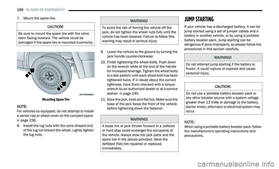
7. Mount the spare tire.
Mounting Spare Tire
NOTE:
For vehicles so equipped, do not attempt to install
a
center cap or wheel cover on the compact spare
Ú page 236.
8. I nstall the lug nuts with the cone shaped end
of
the lug nut toward the wheel. Lightly tighten
the lug nuts. 9. Low
er the vehicle to the ground by turning the
j
ack handle counterclockwise.
10. Finish tightening the wheel bolts. Push down on
the wrench while at the end of the handle
for increased leverage. Tighten the wheel bolts
in a star pattern until each wheel bolt has been
tightened twice. If in doubt about the correct
tightness, have them checked with a torque
wrench by an authorized dealer or at a service
station
Ú page 245.
11. S tow the jack, tools and flat tire. Make sure the
b
ase of the jack faces the front of the vehicle
before tightening down the fastener.
JUMP STARTING
If your vehicle has a discharged battery, it can be
jump started using a set of jumper cables and a
battery in another vehicle, or by using a portable
battery booster pack. Jump starting can be
dangerous if done improperly, so please follow the
procedures in this section carefully.
NOTE:
When using a portable battery booster pack, follow
t h
e manufacturer's operating instructions and
precautions.
CAUTION!
Be sure to mount the spare tire with the valve
stem facing outward. The vehicle could be
damaged if the spare tire is mounted incorrectly.
WARNING!
To avoid the risk of forcing the vehicle off the
jack, do not tighten the wheel nuts fully until the
vehicle has been lowered. Failure to follow this
warning may result in serious injury.
WARNING!
A loose tire or jack thrown forward in a collision
or hard stop could endanger the occupants of
the vehicle. Always stow the jack parts and the
spare tire in the places provided. Have the
deflated (flat) tire repaired or replaced
immediately.
WARNING!
Do not attempt jump starting if the battery is
frozen. It could rupture or explode and cause
personal injury.
CAUTION!
Do not use a portable battery booster pack or
any other booster source with a system voltage
greater than 12 Volts or damage to the battery,
starter motor, alternator or electrical system may
occur.