2021 ALFA ROMEO STELVIO inflation pressure
[x] Cancel search: inflation pressurePage 199 of 280

197
13. Rotate the extension lever clockwise untilthe round pin on the jack engages in the
hole in the lifting block located about
6 inches (15 cm) from the outside edge of
the body. The lifting points are marked by
triangles visible on the plastic body
panel.
Jacking Point Indicators
14. Raise the vehicle by turning the jack screw clockwise, using the swivel wrench. Raise
the vehicle only until the tire just clears the
surface and enough clearance is obtained
to install the compact spare tire. Minimum
tire lift provides maximum stability. 15. Remove the five wheel bolts and take the
wheel off.
16. Make sure the contact surfaces between compact spare tire and hub are clean so
that the fastening bolts will not come
loose.
17. Fit the compact spare tire by inserting the first wheel bolt for two threads into the
hole closest to the valve.
18. Take the wheel wrench and tighten the wheel bolts.
19. Inflate the compact spare tire by removing the cap from its inflation valve and
screwing on the compressor inflation hose
fitting. 20. Make sure that the switch on the
compressor is in the (off) O position, open
the liftgate and insert the plug into the
power socket in the cargo area, or on the
center console and start the engine. Place
the on/off switch in the (on) I position.
Attaching Compressor To Tire
21. Inflate the compact spare tire to a pres -
sure of 43.5 psi (3 bar).
NOTE:
If spare tire is overinflated, be sure to lower
the psi in the tire to the recommended amount
by using the deflation button on the air
compressor.
22. Operate the wheel wrench on the jack to lower the vehicle.
CAUTION!
Do not attempt to raise the vehicle by
jacking on locations other than those
indicated in the Jacking Instructions for this
vehicle.
WARNING!
Raising the vehicle higher than necessary
can make the vehicle less stable. It could
slip off the jack and hurt someone near it.
Raise the vehicle only enough to remove
the tire.
CAUTION!
Be sure to mount the spare tire with the
valve stem facing outward. The vehicle
could be damaged if the spare tire is
mounted incorrectly.
6 — Air Compressor
7 — Pressure Gauge
8 — Power Button
21_GU_OM_EN_USC_t.book Page 197
Page 201 of 280
199
(Continued)
An instruction pamphlet for reference in
prompt and correct use of the Tire Service
Kit, which must be then given to the
personnel dealing with the sealant-treated
tire
A pair of protective gloves
Some adapters, for inflating different
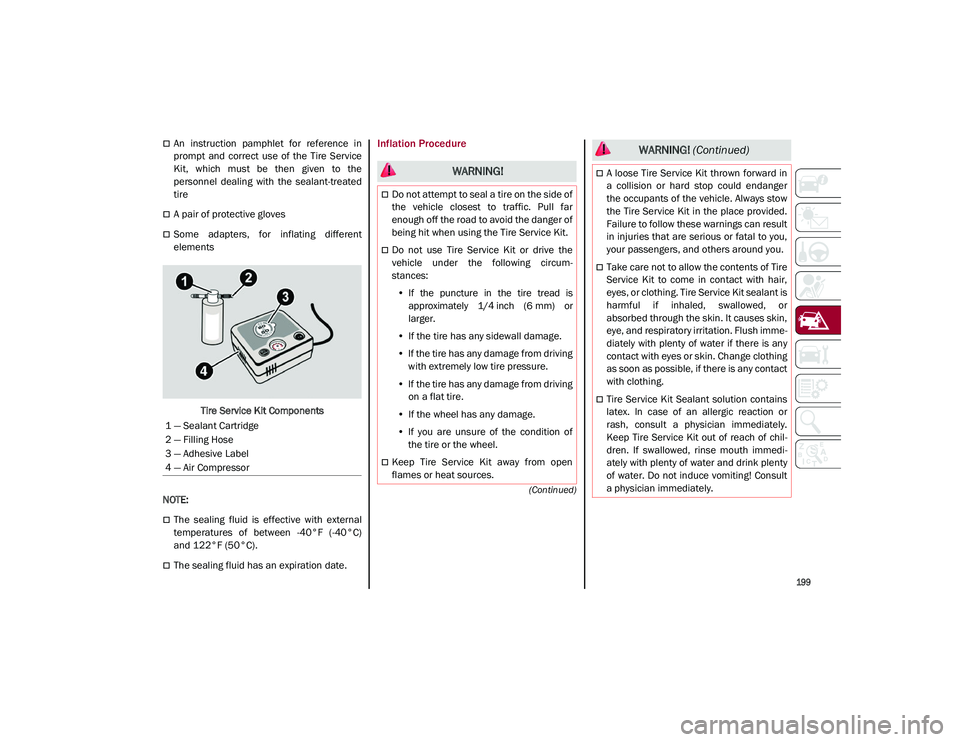
elementsTire Service Kit Components
NOTE:
The sealing fluid is effective with external
temperatures of between -40°F (-40°C)
and 122°F (50°C).
The sealing fluid has an expiration date.
Inflation Procedure
1 — Sealant Cartridge
2 — Filling Hose
3 — Adhesive Label
4 — Air Compressor
WARNING!
Do not attempt to seal a tire on the side of
the vehicle closest to traffic. Pull far
enough off the road to avoid the danger of
being hit when using the Tire Service Kit.
Do not use Tire Service Kit or drive the
vehicle under the following circum -
stances:
• If the puncture in the tire tread is
approximately 1/4 inch (6 mm) or
larger.
• If the tire has any sidewall damage.
• If the tire has any damage from driving
with extremely low tire pressure.
• If the tire has any damage from driving
on a flat tire.
• If the wheel has any damage.
• If you are unsure of the condition of
the tire or the wheel.
Keep Tire Service Kit away from open
flames or heat sources.
A loose Tire Service Kit thrown forward in
a collision or hard stop could endanger
the occupants of the vehicle. Always stow
the Tire Service Kit in the place provided.
Failure to follow these warnings can result
in injuries that are serious or fatal to you,
your passengers, and others around you.
Take care not to allow the contents of Tire
Service Kit to come in contact with hair,
eyes, or clothing. Tire Service Kit sealant is
harmful if inhaled, swallowed, or
absorbed through the skin. It causes skin,
eye, and respiratory irritation. Flush imme -
diately with plenty of water if there is any
contact with eyes or skin. Change clothing
as soon as possible, if there is any contact
with clothing.
Tire Service Kit Sealant solution contains
latex. In case of an allergic reaction or
rash, consult a physician immediately.
Keep Tire Service Kit out of reach of chil -
dren. If swallowed, rinse mouth immedi -
ately with plenty of water and drink plenty
of water. Do not induce vomiting! Consult
a physician immediately.
WARNING! (Continued)
21_GU_OM_EN_USC_t.book Page 199
Page 202 of 280
IN CASE OF EMERGENCY
200
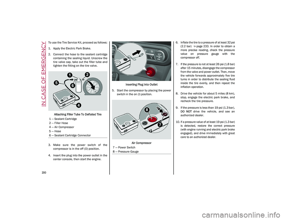
To use the Tire Service Kit, proceed as follows:
1. Apply the Electric Park Brake.
2. Connect the hose to the sealant cartridgecontaining the sealing liquid. Unscrew the
tire valve cap, take out the filler tube and
tighten the fitting on the tire valve.
Attaching Filler Tube To Deflated Tire
3. Make sure the power switch of the compressor is in the off (O) position.
4. Insert the plug into the power outlet in the center console, then start the engine. Inserting Plug Into Outlet
5. Start the compressor by placing the power switch in the on (I) position.
Air Compressor
6. Inflate the tire to a pressure of at least 32 psi
(2.2 bar)
Ú page 233. In order to obtain a
more precise reading, check the pressure
value on pressure gauge with the
compressor off.
7. If the pressure is not at least 26 psi (1.8 bar) after 15 minutes, disengage the compressor
from the valve and power outlet. Then, move
the vehicle forwards approximately five tire
turns in order to distribute the sealing fluid
inside the tire evenly, and then repeat the
inflation operation.
8. Drive the vehicle for about 5 miles (8 km), stop, engage the electric park brake, and
recheck the tire pressure.
9. If the pressure is less than 19 psi (1.3 bar), DO NOT drive the vehicle, and see an
authorized dealer.
10. If a pressure value of at least 19 psi (1.3 bar) is detected, restore the correct pressure
(with engine running and electric park brake
engaged), and drive immediately with great
care to an authorized dealer.
1 — Sealant Cartridge
2 — Filler Hose
4 — Air Compressor
5 — Hose
6 — Sealant Cartridge Connector
7 — Power Switch
8 — Pressure Gauge
21_GU_OM_EN_USC_t.book Page 200
Page 210 of 280
208
SERVICING AND MAINTENANCE
Correct servicing permits the performance of
the vehicle to be maintained over time, as well
as limited running costs and safeguarding the
efficiency of the safety systems.
SCHEDULED SERVICING
Correct servicing is crucial for guaranteeing a
long life for the vehicle under the best condi-
tions.
For this reason, Alfa Romeo has planned a
series of checks and services for your vehicle
at fixed intervals based on distance and time,
as described in the Scheduled Servicing Plan.
Before each service, it is always necessary to
carefully follow the instructions in the Sched -
uled Servicing Plan (e.g. periodically check
level of fluids, tire pressure, etc.).
Scheduled Servicing is offered by an autho -
rized dealer according to a set time schedule.
If, during each operation, in addition to the
ones scheduled, the need arises for further
replacements or repairs, these may be carried
out with the owner’s explicit consent only.
NOTE:
Scheduled Servicing intervals are required by
the manufacturer. Failure to have them
carried out may invalidate the New Vehicle
Limited Warranty.
You are advised to inform an authorized
dealer of any small operating irregularities
without waiting for the next service.
Periodic Checks
Every month or every 620 miles (1,000 km) or
before long trips check and, if necessary, top
off:
Engine coolant level.
Brake fluid level (if insufficient, see an
authorized dealer as soon as possible).
Windshield washer fluid level.
Tire inflation pressure and condition.
Operation of lighting system (headlights,
direction indicators, hazard warning lights,
etc.).
Operation of windshield washing/wiping
system and positioning/wear of wiper
blades.
Inspect the CV/Universal joints.
Oil consumption of the engine depends on
conditions and driving style. For this reason,
the engine oil level must be checked every
1,860 miles (3,000 km), and top off if neces -
sary; for further information
Ú
page 215.
Heavy Usage Of The Vehicle
If the vehicle is used under one of the following
conditions:
Dusty roads.
Short, repeated journeys less than 4 miles
(7 km) at sub-zero outside temperatures.
Engine often idling or driving long distances
at low speeds or long periods of inactivity.
In the event of a long period of inactivity.
The following checks must be carried out more
often than indicated in the Scheduled
Servicing Plan:
Check cleanliness of hood and liftgate
locks, cleanliness and lubrication of
linkage.
Visually inspect conditions of: engine, trans -
mission, pipes and hoses (exhaust/fuel
system/brakes) and rubber elements
(sleeves/bushes, etc.).
Check battery charge and battery fluid level
(electrolyte).
Visually inspect conditions of the accessory
drive belts.
Check and, if necessary, change engine oil
and replace oil filter.
Check and, if necessary, replace cabin air
filter.
Check and, if necessary, replace air cleaner.
Severe Duty All Models
Change engine oil at 4,000 miles (6,500 km)
if the vehicle is operated in a dusty and
off-road environment or is operated predomi -
nately at idle or only very low engine RPM. This
type of vehicle use is considered Severe Duty.
21_GU_OM_EN_USC_t.book Page 208
Page 237 of 280
235
65, 85, 80 = Aspect ratio in percent (%)
Ratio of section height to section width of tire, or
10.5 = Section width in inches (in)
R = Construction code
"R" means radial construction, or
"D" means diagonal or bias construction
15, 16, 18 = Rim diameter in inches (in)
Service Description:
95 = Load Index
A numerical code associated with the maximum load a tire can carry
H = Speed Symbol
A symbol indicating the range of speeds at which a tire can carry a load corresponding to its load index under certain operating conditions
The maximum speed corresponding to the speed symbol should only be achieved under specified operating conditions (i.e., tire pressure,
vehicle loading, road conditions, and posted speed limits)
Load Identification:
Absence of the following load identification symbols on the sidewall of the tire indicates a Standard Load (SL) tire:
XL = Extra load (or reinforced) tire, or
LL = Light load tire or
C, D, E, F, G = Load range associated with the maximum load a tire can carry at a specified pressure
Maximum Load – Maximum load indicates the maximum load this tire is designed to carry
Maximum Pressure – Maximum pressure indicates the maximum permissible cold tire inflation pressure for this tire
EXAMPLE:
21_GU_OM_EN_USC_t.book Page 235
Page 238 of 280
SERVICING AND MAINTENANCE
236
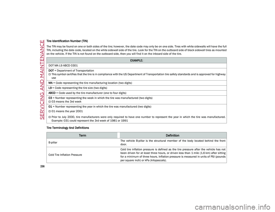
Tire Identification Number (TIN)
The TIN may be found on one or both sides of the tire; however, the date code may only be on one side. Tires with white sidewalls will have the full
TIN, including the date code, located on the white sidewall side of the tire. Look for the TIN on the outboard side of black sidewall tires as mounted
on the vehicle. If the TIN is not found on the outboard side, then you will find it on the inboard side of the tire.
Tire Terminology And Definitions
EXAMPLE:
DOT MA L9 ABCD 0301
DOT = Department of Transportation
This symbol certifies that the tire is in compliance with the US Department of Transportation tire safety standards and is approved for highway
use
MA = Code representing the tire manufacturing location (two digits)
L9 = Code representing the tire size (two digits)
ABCD = Code used by the tire manufacturer (one to four digits)
03 = Number representing the week in which the tire was manufactured (two digits)
03 means the 3rd week
01 = Number representing the year in which the tire was manufactured (two digits)
01 means the year 2001
Prior to July 2000, tire manufacturers were only required to have one number to represent the year in which the tire was manufactured.
Example: 031 could represent the 3rd week of 1981 or 1991
TermDefinition
B-pillar The vehicle B-pillar is the structural member of the body located behind the front
door.
Cold Tire Inflation Pressure Cold tire inflation pressure is defined as the tire pressure after the vehicle has not
been driven for at least three hours, or driven less than 1 mile (1.6 km) after sitting
for a minimum of three hours. Inflation pressure is measured in units of PSI (pounds
per square inch) or kPa (kilopascals).
21_GU_OM_EN_USC_t.book Page 236
Page 239 of 280
237
Tire Loading And Tire Pressure
NOTE:
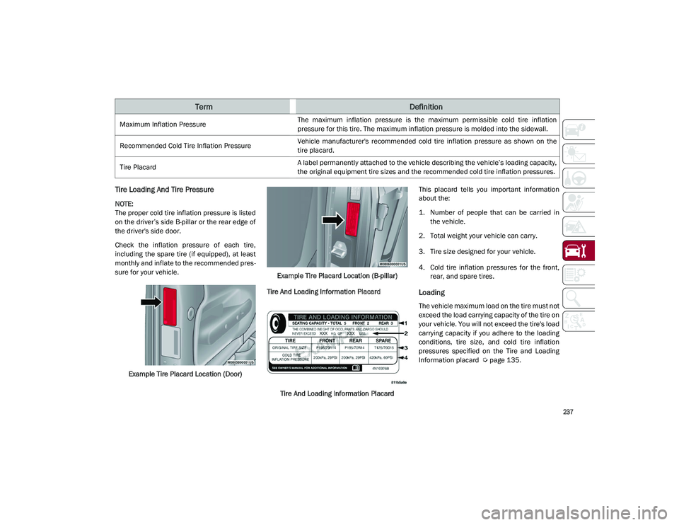
The proper cold tire inflation pressure is listed
on the driver’s side B-pillar or the rear edge of
the driver's side door.
Check the inflation pressure of each tire,
including the spare tire (if equipped), at least
monthly and inflate to the recommended pres-
sure for your vehicle.
Example Tire Placard Location (Door) Example Tire Placard Location (B-pillar)
Tire And Loading Information Placard
Tire And Loading Information Placard This placard tells you important information
about the:
1. Number of people that can be carried in
the vehicle.
2. Total weight your vehicle can carry.
3. Tire size designed for your vehicle.
4. Cold tire inflation pressures for the front, rear, and spare tires.
Loading
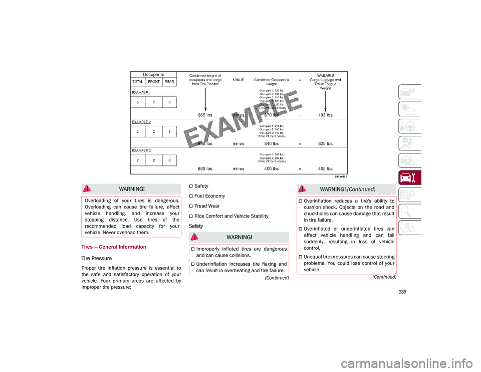
The vehicle maximum load on the tire must not
exceed the load carrying capacity of the tire on
your vehicle. You will not exceed the tire's load
carrying capacity if you adhere to the loading
conditions, tire size, and cold tire inflation
pressures specified on the Tire and Loading
Information placard
Ú
page 135.
Maximum Inflation Pressure
The maximum inflation pressure is the maximum permissible cold tire inflation
pressure for this tire. The maximum inflation pressure is molded into the sidewall.
Recommended Cold Tire Inflation Pressure Vehicle manufacturer's recommended cold tire inflation pressure as shown on the
tire placard.
Tire Placard A label permanently attached to the vehicle describing the vehicle’s loading capacity,
the original equipment tire sizes and the recommended cold tire inflation pressures.
TermDefinition
21_GU_OM_EN_USC_t.book Page 237
Page 241 of 280
239
(Continued)
(Conti n
ued)
Tires — General Information
Tire Pressure
Proper tire inflation pressure is essential to
the safe and satisfactory operation of your
vehicle. Four primary areas are affected by
improper tire pressure:
Safety
Fuel Economy
Tread Wear
Ride Comfort and Vehicle Stability
Safety
WARNING!
Overloading of your tires is dangerous.
Overloading can cause tire failure, affect
vehicle handling, and increase your
stopping distance. Use tires of the
recommended load capacity for your
vehicle. Never overload them.
WARNING!
Improperly inflated tires are dangerous
and can cause collisions.
Underinflation increases tire flexing and
can result in overheating and tire failure.
Overinflation reduces a tire's ability to
cushion shock. Objects on the road and
chuckholes can cause damage that result
in tire failure.
Overinflated or underinflated tires can
affect vehicle handling and can fail
suddenly, resulting in loss of vehicle
control.
Unequal tire pressures can cause steering
problems. You could lose control of your
vehicle.
WARNING! (Continued)
21_GU_OM_EN_USC_t.book Page 239