Page 199 of 280

197
13. Rotate the extension lever clockwise untilthe round pin on the jack engages in the
hole in the lifting block located about
6 inches (15 cm) from the outside edge of
the body. The lifting points are marked by
triangles visible on the plastic body
panel.
Jacking Point Indicators
14. Raise the vehicle by turning the jack screw clockwise, using the swivel wrench. Raise
the vehicle only until the tire just clears the
surface and enough clearance is obtained
to install the compact spare tire. Minimum
tire lift provides maximum stability. 15. Remove the five wheel bolts and take the
wheel off.
16. Make sure the contact surfaces between compact spare tire and hub are clean so
that the fastening bolts will not come
loose.
17. Fit the compact spare tire by inserting the first wheel bolt for two threads into the
hole closest to the valve.
18. Take the wheel wrench and tighten the wheel bolts.
19. Inflate the compact spare tire by removing the cap from its inflation valve and
screwing on the compressor inflation hose
fitting. 20. Make sure that the switch on the
compressor is in the (off) O position, open
the liftgate and insert the plug into the
power socket in the cargo area, or on the
center console and start the engine. Place
the on/off switch in the (on) I position.
Attaching Compressor To Tire
21. Inflate the compact spare tire to a pres -
sure of 43.5 psi (3 bar).
NOTE:
If spare tire is overinflated, be sure to lower
the psi in the tire to the recommended amount
by using the deflation button on the air
compressor.
22. Operate the wheel wrench on the jack to lower the vehicle.
CAUTION!
Do not attempt to raise the vehicle by
jacking on locations other than those
indicated in the Jacking Instructions for this
vehicle.
WARNING!
Raising the vehicle higher than necessary
can make the vehicle less stable. It could
slip off the jack and hurt someone near it.
Raise the vehicle only enough to remove
the tire.
CAUTION!
Be sure to mount the spare tire with the
valve stem facing outward. The vehicle
could be damaged if the spare tire is
mounted incorrectly.
6 — Air Compressor
7 — Pressure Gauge
8 — Power Button
21_GU_OM_EN_USC_t.book Page 197
Page 232 of 280
SERVICING AND MAINTENANCE
230
Types Of Bulbs
Replacement Bulbs
The vehicle may be equipped with the following bulbs
Glass Bulbs (Type A) : They are press-fitted. Pull to extract.
Bayonet-Type Bulbs (Type B) : To remove them from their holder, press the bulb and turn it counterclockwise,
then extract it.
Tubular Bulbs (Type C) : Release them from their contacts to remove.
Halogen Bulbs (Type D) : To remove the bulb, turn the connector to the side and pull it out.
Halogen Bulbs (Type E) : To remove the bulb, turn it counterclockwise.
Xenon Gas Discharge Bulb (Type F) : to remove the bulb, contact an authorized dealer.
Light bulbsTypePower
Front direction indicators* PY24W24W
Rear Fog lights * H1155 W
Main beam headlights, front side lights/daylight running lights (DRL)* H1555/15W
Dipped beam headlights* H755W
Main beam/dipped beam headlights (Xenon gas discharge) D3S35W
21_GU_OM_EN_USC_t.book Page 230
Page 233 of 280

231
*Only for basic version headlight with halogen main beam/dipped beam headlights
Replacing Exterior Bulbs
NOTE:
Only replace bulbs when the engine is off. Also
ensure that the engine is cold, to prevent the
risk of burns.
Front Light Cluster
Direction Indicators
Proceed with the directions below to change
bulbs:
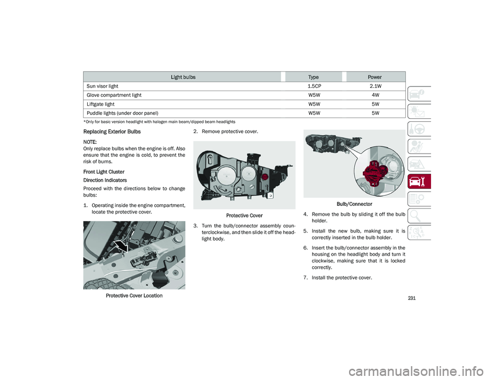
1. Operating inside the engine compartment,locate the protective cover.
Protective Cover Location 2. Remove protective cover.
Protective Cover
3. Turn the bulb/connector assembly coun -
terclockwise, and then slide it off the head -
light body. Bulb/Connector
4. Remove the bulb by sliding it off the bulb holder.
5. Install the new bulb, making sure it is correctly inserted in the bulb holder.
6. Insert the bulb/connector assembly in the housing on the headlight body and turn it
clockwise, making sure that it is locked
correctly.
7. Install the protective cover.
Sun visor light
1.5CP2.1W
Glove compartment light W5W4W
Liftgate light W5W5W
Puddle lights (under door panel) W5W5W
Light bulbsTypePower
21_GU_OM_EN_USC_t.book Page 231