2021 ALFA ROMEO GIULIA width
[x] Cancel search: widthPage 30 of 284

GETTING TO KNOW YOUR VEHICLE
28
When the function is enabled, the indicator on
the button will illuminate.Heated Steering Wheel Button
NOTE:
The engine must be running for the heated
steering wheel to operate.
For information on use with the Remote Start
system, see
Ú
page 21.DRIVER MEMORY SETTINGS — IF
EQUIPPED
This feature allows the driver to store up to
three different memory profiles for easy recall
through a memory switch. Each memory
profile saves desired position settings for the
following features:
Driver seat
Side mirrors
The memory setting switch is located on the
outboard side of the driver’s seat. The switch
consists of three buttons, one for each
memory profile.
Seatback Width Adjustment
Programming The Memory Feature
To create a new memory profile, perform the
following:
1. Place the vehicle’s ignition in the ACC posi -
tion (do not start the engine), and make
sure the driver’s door is closed.
NOTE:
A memory profile can also be set for three
minutes after the driver’s door has been
opened.
2. Adjust all memory profile settings to desired preferences, driver’s seat and
mirror positions.
3. Push and hold the memory button you want to program for 1.5 seconds.
NOTE:
When a new profile as been set, the previously
set profile for that button will be overwritten.
Memory Position Recall
To recall a previously set position, push and
release the memory profile button assigned to
the desired positions.
NOTE:
Memory position recall can be done for
approximately three minutes after the doors
have been opened, and for approximately one
minute after the ignition is placed in the OFF
position.
WARNING!
Persons who are unable to feel pain to the
skin because of advanced age, chronic
illness, diabetes, spinal cord injury, medi -
cation, alcohol use, exhaustion, or other
physical conditions must exercise care
when using the steering wheel heater. It
may cause burns even at low tempera -
tures, especially if used for long periods.
Do not place anything on the steering
wheel that insulates against heat, such as
a blanket or steering wheel covers of any
type and material. This may cause the
steering wheel heater to overheat.
4 — Power Adjustable Bolster Buttons
5 — Driver Memory Settings Buttons
21_GA_OM_EN_USC_t.book Page 28
Page 35 of 284

33
Power Lumbar
The power lumbar switch is located on the
outboard side of the power seat. Push the
switch forward or rearward to increase or
decrease the lumbar support. Push the switch
upward or downward to raise or lower the
lumbar support.
Seat Cushion Extension — If Equipped
Lift the adjustment lever and push the front of
the cushion forward or rearward to extend the
cushion by a few inches (centimeters).Seat Cushion Extension
Power Bolster Adjustment — If Equipped
Push the power bolster adjustment buttons to
regulate the width of the backrest through the
lateral padding.
Seatback Width Adjustment
Easy Entry Function
The Easy Entry function is designed to move
the driver side seat forward automatically by
2.36 inches (60 mm) to make it easier for the
driver to get in and out of the car.
The movement is activated only if the seat is
set to a driving position which is in front of the
B-Pillar of the vehicle. The function is associated with power driver
seats for each of the three stored positions.
The Easy Entry function can be activated/
deactivated through the radio system. Refer to
the Information and Entertainment System
Owner’s Manual Supplement for further infor
-
mation.
Heated Seats — If Equipped
For information on use with the Remote Start
system, see
Ú
page 21.
6 — Adjustment Lever
4 — Power Adjustable Bolster Buttons
5 — Driver Memory Settings Buttons
WARNING!
Persons who are unable to feel pain to the
skin because of advanced age, chronic
illness, diabetes, spinal cord injury, medi
-
cation, alcohol use, exhaustion or other
physical condition must exercise care
when using the seat heater. It may cause
burns even at low temperatures, espe -
cially if used for long periods of time.
Do not place anything on the seat or seat -
back that insulates against heat, such as
a blanket or cushion. This may cause the
seat heater to overheat. Sitting in a seat
that has been overheated could cause
serious burns due to the increased
surface temperature of the seat.
21_GA_OM_EN_USC_t.book Page 33
Page 119 of 284

117
The right and left lane boundaries must be
visible
The vehicle speed must be between 0 and
90 mph (0 and 145 km/h)
The camera, radar, and radio system must
be functioning properly
The road lane width must be between 8.5 ft
and 13.7 ft (2.6 m and 4.2 m)
The turn signals must not be activated
The HAS system must be functioning prop-
erly
Other operating limits:
If the speed of ACC can be set to a higher
value (top speed 110 mph (180 km/h), HAS
is only available as long as the vehicle
speed is equal to or less than 90 mph
(145 km/h).
When the ACC speed is reduced and the
vehicle speed is less than 90 mph
(145 km/h), the system will automatically
reactivate.
If the ACC speed is set to 90 mph (145 km/h),
traveling downhill may increase the vehicle
speed. The HAS system will deactivate until
the speed returns to 90 mph (145 km/h).
Indications On The Display
The HAS system status can always be viewed
in the instrument cluster display.
The system status is indicated by the color of
the symbol on the display.
The HAS system uses sensors in the steering
wheel to detect if the driver’s hands are on it.
If the driver’s hands are not on the steering
wheel, a series of warnings will appear in the
instrument cluster display to alert the driver to
reposition their hands on the steering wheel.
An acoustic signal will also sound. After a
period of time, the HAS system will disable if
the driver’s hands do not return to the steering
wheel.
After a period of time, the HAS system will
disable if the driver has not repositioned their
hands on the steering wheel.
When the system does not detect hands on
the steering wheel, it will warn the driver by
displaying a dedicated screen on the instru -
ment cluster display.
System Status
Active System
When the system is active, the screen below
will appear in the “Driver Assistance” menu on
the instrument cluster display.
HAS Active
If on a different menu screen, a symbol will
appear on the instrument cluster display indi -
cating that the system is active.
When the driver’s hands are removed from the
steering wheel, the system disables after a few
seconds. A screen will appear in the instru-
ment cluster display warning the driver to
return their hands to the steering wheel.
21_GA_OM_EN_USC_t.book Page 117
Page 122 of 284

STARTING AND OPERATING
120
Suspension Conditions
The following operations will suspend the TJA
system:
Pressing the brake pedal
Opening the driver’s door
Disabling ACC
If the vehicle speed exceeds 37 mph
(60 km/h)
Releasing the driver’s seat belt
Placing the gear selector in PARK,
REVERSE, or NEUTRAL
If the Forward Collision Warning system or
“Active Braking” intervenes
Automatic Deactivation
System operation will be temporarily disabled
under the following conditions:
When traveling around narrow bends
If the lane boundaries are not detected
One of the two lines is interrupted
The sun is low and reflects on the radar
camera
If the turn signals are activated
If the driver intentionally changes lanes
without using the turn signal
If manual steering begins
If the driver’s hands are removed from the
steering wheel
When there is no surrounding traffic and
there are no horizontal lane boundaries
If the system is not functioning properly
If lateral acceleration is high
NOTE:
When TJA is turned off, the symbol in the
instrument cluster display will turn red, and
then grey.
A sensor in the steering wheel detects
whether the driver’s hands are placed on
the steering wheel.
When the automatic suspension conditions
are over, the TJA system will be automatically
reactivated.
Operation
The TJA system can only operate when the
driver’s hands are on the steering wheel.
If the system detects that the driver’s hands
have been removed from the steering wheel, a
message will appear in the instrument cluster
display to alert the driver to place their hands
back on the wheel.
NOTE:
If the vehicle begins to cross the lane
boundary, the steering wheel will vibrate
and a dedicated screen will appear in the
instrument cluster display.
The TJA system may take up to five seconds
to become active once all conditions are met.
The following conditions must be met in order
to activate the system:
The TJA system must be enabled
The Adaptive Cruise Control (ACC) system
must be turned on
The right and left lane boundaries must be
recognized by the system
The vehicle must be traveling at a speed
between 0 and 37 mph (0 and 60 km/h)
The camera, radar, and radio system must
be functioning properly
The road lane width must be between 8.5 ft
and 13.7 ft (2.6 m and 4.2 m)
The turn signals must be turned off
The TJA system must be functioning properly
If the ACC speed is set to 37 mph (60 km/h)
or less, traveling downhill may increase the
vehicle speed. The system will remain inac -
tive until the speed returns to 37 mph
(60 km/h) or less.
21_GA_OM_EN_USC_t.book Page 120
Page 136 of 284

STARTING AND OPERATING
134
REAR BACK UP CAMERA /
DYNAMIC GRIDLINES
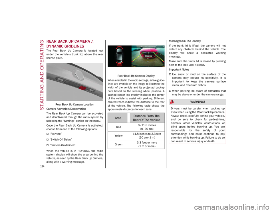
The Rear Back Up Camera is located just
under the vehicle’s trunk lid, above the rear
license plate.Rear Back Up Camera Location
Camera Activation/Deactivation
The Rear Back Up Camera can be activated
and deactivated through the radio system by
selecting the “Settings” option on the menu.
Once the Rear Back Up Camera is activated,
choose from one of the following options:
“Activate”
“Switch-Off Delay”
“Camera Guidelines”
When the vehicle is in REVERSE, the radio
system display will show the area behind the
vehicle, as seen by the Rear Back Up Camera,
along with a warning message. Rear Back Up Camera Display
When enabled in the radio settings, active guide -
lines are overlaid on the image to illustrate the
width of the vehicle and its projected backup
path based on the steering wheel position. A
dashed center line overlay indicates the center
of the vehicle to assist with parking. Different
colored zones indicate the distance to the rear
of the vehicle. The following table shows the
approximate distances for each zone:
Messages On The Display
If the trunk lid is lifted, the camera will not
detect any obstacle behind the vehicle. The
display will show a dedicated warning
message.
Make sure the trunk lid is closed by pushing
next to the lock until it clicks.
Important Notes
Ice, snow or mud on the surface of the
camera may reduce its sensitivity. It is
important to keep the camera surface
clean, and free from debris.
When parking, be aware of obstacles that
may be above or under the camera range.
AreaDistance From The
Rear Of The Vehicle
Red 0–11.8 inches
(0–30 cm)
Yellow 11.8 inches to 3.3 feet
(30 cm–1 m)
Green 3.3 feet or more
(1 m or more)
WARNING!
Drivers must be careful when backing up
even when using the Rear Back Up Camera.
Always check carefully behind your vehicle,
and be sure to check for pedestrians,
animals, other vehicles, obstructions, or
blind spots before backing up. You are
responsible for the safety of your
surroundings and must continue to pay
attention while backing up. Failure to do so
can result in serious injury or death.
21_GA_OM_EN_USC_t.book Page 134
Page 151 of 284

149
System Availability
Aggressive driving of the car, or driving on the
median lines, will prevent the correct opera-
tion of the system.
In case of intervention of the stability and
braking systems (FCW, ESC, ABS) they will
prevent the system from operating.
Lane change will disable the system for a
certain period of time.
The road must also comply with some specific
characteristics, such as:
Maximum/minimum lane width.
Clearly identified and defined double yellow
lines and, for a limited period of time, a lane
with a single demarcation line.
NOTE:
In some cases, for a limited period of time, the
system may be activated by a lane with a
single median line.
In cases of good road surface conditions, the
system could correctly recognize other types
of valid lane markings (e.g. road edges, side -
walks, etc.). Hands Presence On The Steering Wheel
Detection
The system is able to detect the presence of
the driver’s hands on the steering wheel.
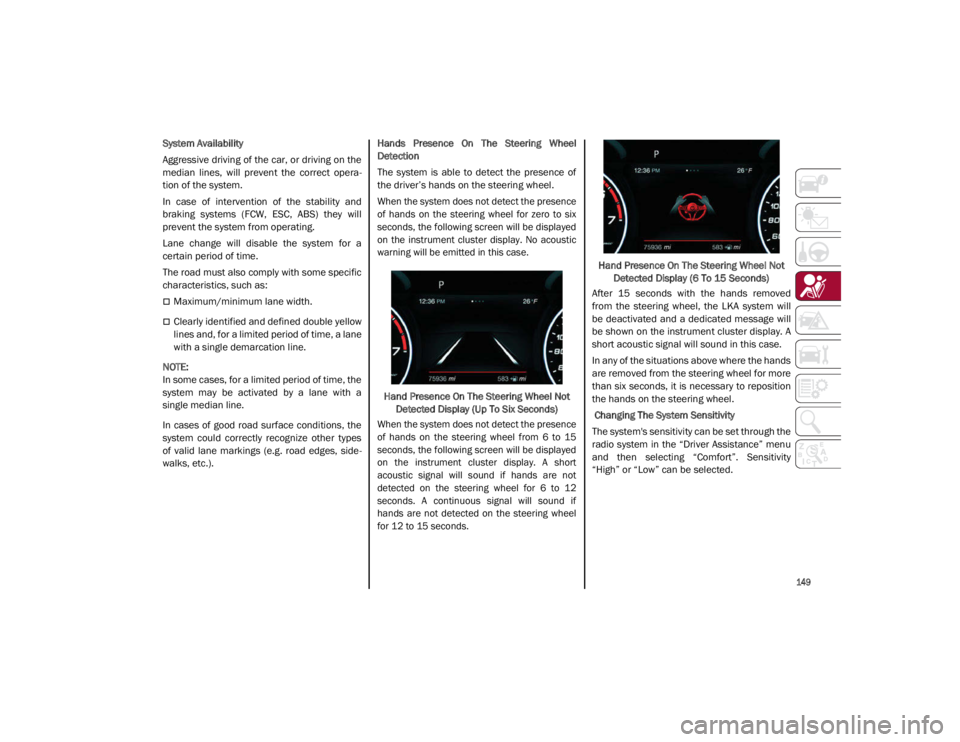
When the system does not detect the presence
of hands on the steering wheel for zero to six
seconds, the following screen will be displayed
on the instrument cluster display. No acoustic
warning will be emitted in this case.
Hand Presence On The Steering Wheel Not Detected Display (Up To Six Seconds)
When the system does not detect the presence
of hands on the steering wheel from 6 to 15
seconds, the following screen will be displayed
on the instrument cluster display. A short
acoustic signal will sound if hands are not
detected on the steering wheel for 6 to 12
seconds. A continuous signal will sound if
hands are not detected on the steering wheel
for 12 to 15 seconds.
Hand Presence On The Steering Wheel Not
Detected Display (6 To 15 Seconds)
After 15 seconds with the hands removed
from the steering wheel, the LKA system will
be deactivated and a dedicated message will
be shown on the instrument cluster display. A
short acoustic signal will sound in this case.
In any of the situations above where the hands
are removed from the steering wheel for more
than six seconds, it is necessary to reposition
the hands on the steering wheel.
Changing The System Sensitivity
The system's sensitivity can be set through the
radio system in the “Driver Assistance” menu
and then selecting “Comfort”. Sensitivity
“High” or “Low” can be selected.
21_GA_OM_EN_USC_t.book Page 149
Page 236 of 284

SERVICING AND MAINTENANCE
234
TIRES
Tire Safety Information
Tire safety information will cover aspects of
the following information: Tire Markings, Tire
Identification Numbers, Tire Terminology and
Definitions, Tire Pressures, and Tire Loading.
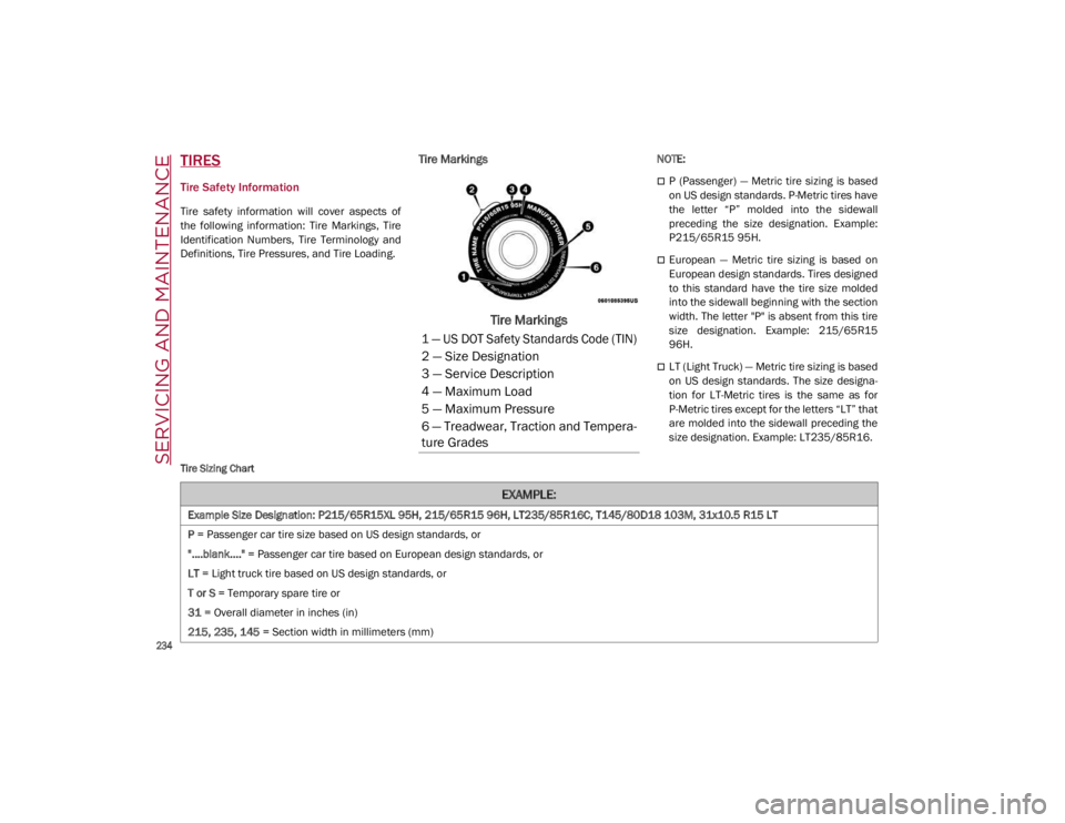
Tire Markings
Tire Markings
NOTE:
P (Passenger) — Metric tire sizing is based
on US design standards. P-Metric tires have
the letter “P” molded into the sidewall
preceding the size designation. Example:
P215/65R15 95H.
European — Metric tire sizing is based on
European design standards. Tires designed
to this standard have the tire size molded
into the sidewall beginning with the section
width. The letter "P" is absent from this tire
size designation. Example: 215/65R15
96H.
LT (Light Truck) — Metric tire sizing is based
on US design standards. The size designa-
tion for LT-Metric tires is the same as for
P-Metric tires except for the letters “LT” that
are molded into the sidewall preceding the
size designation. Example: LT235/85R16.
Tire Sizing Chart
1 — US DOT Safety Standards Code (TIN)
2 — Size Designation
3 — Service Description
4 — Maximum Load
5 — Maximum Pressure
6 — Treadwear, Traction and Tempera -
ture Grades
EXAMPLE:
Example Size Designation: P215/65R15XL 95H, 215/65R15 96H, LT235/85R16C, T145/80D18 103M, 31x10.5 R15 LT
P = Passenger car tire size based on US design standards, or
"....blank...." = Passenger car tire based on European design standards, or
LT = Light truck tire based on US design standards, or
T or S = Temporary spare tire or
31 = Overall diameter in inches (in)
215, 235, 145 = Section width in millimeters (mm)
21_GA_OM_EN_USC_t.book Page 234
Page 237 of 284

235
65, 85, 80 = Aspect ratio in percent (%)
Ratio of section height to section width of tire, or
10.5 = Section width in inches (in)
R = Construction code
"R" means radial construction, or
"D" means diagonal or bias construction
15, 16, 18 = Rim diameter in inches (in)
Service Description:
95 = Load Index
A numerical code associated with the maximum load a tire can carry
H = Speed Symbol
A symbol indicating the range of speeds at which a tire can carry a load corresponding to its load index under certain operating conditions
The maximum speed corresponding to the speed symbol should only be achieved under specified operating conditions (i.e., tire pressure,
vehicle loading, road conditions, and posted speed limits)
Load Identification:
Absence of the following load identification symbols on the sidewall of the tire indicates a Standard Load (SL) tire:
XL = Extra load (or reinforced) tire, or
LL = Light load tire or
C, D, E, F, G = Load range associated with the maximum load a tire can carry at a specified pressure
Maximum Load – Maximum load indicates the maximum load this tire is designed to carry
Maximum Pressure – Maximum pressure indicates the maximum permissible cold tire inflation pressure for this tire
EXAMPLE:
21_GA_OM_EN_USC_t.book Page 235