2021 ALFA ROMEO GIULIA gas type
[x] Cancel search: gas typePage 14 of 284

12
Exhaust System ...................................220
Engine Cooling System ........................ 220
Braking System ....................................222
Automatic Transmission ......................222
Replacing The Battery ......................... 223
FUSES ..................................................223
BULB REPLACEMENT ..........................228
TIRES ...................................................... 234
Tire Safety Information ....................... 234
Tires — General Information ...............241
Spare Tires — If Equipped .................. 246
Wheel And Wheel Trim Care ...............246
Tire Types ............................................. 247
Snow Traction Devices ........................ 248
Tire Rotation Recommendations ........249
DEPARTMENT OF TRANSPORTATION
UNIFORM TIRE QUALITY GRADES ........ 250
Treadwear ............................................ 250
Traction Grades ...................................250
Temperature Grades ...........................250
STORING THE VEHICLE ........................ 250
BODYWORK ........................................... 252
Protection Against Atmospheric
Agents ................................................... 252 Corrosion Warranty .............................. 252
Preserving The Bodywork ....................252
INTERIORS ............................................. 253
Seats And Fabric Parts ........................ 253
Leather Seats....................................... 254
Plastic And Coated Parts .....................254
Alcantara Parts — If Equipped.............254
Genuine Leather Surfaces —
If Equipped ...........................................254 Carbon Fiber Parts ............................... 254
TECHNICAL SPECIFICATIONS
VEHICLE IDENTIFICATION
NUMBER (VIN)........................................ 255
Vehicle Identification Number (VIN)
Plate ..................................................... 255
ENGINE ................................................... 256
POWER SUPPLY ..................................... 257
TRANSMISSION...................................... 258 BRAKES .................................................. 258SUSPENSION.......................................... 259
STEERING SYSTEM ................................ 259
DIMENSIONS — 2.0L ENGINE ............... 260
DIMENSIONS — 2.9L Engine ................. 261
WEIGHTS — 2.0L ENGINE ...................... 262
WEIGHTS — 2.9L ENGINE ...................... 262
FUEL REQUIREMENTS ........................... 263
Reformulated Gasoline ...................... 263
Gasoline/Oxygenate Blends ............... 263
CNG And LP Fuel System
Modifications ....................................... 263 Methylcyclopentadienyl Manganese
Tricarbonyl (MMT) In Gasoline ............ 263 Materials Added To Fuel ..................... 264
Fuel System Cautions ......................... 264
FLUID CAPACITIES.................................. 265
2.0L Engine.......................................... 265
2.9L V6 Engine .................................... 266
ENGINE FLUIDS AND LUBRICANTS ....... 267CHASSIS FLUIDS AND LUBRICANTS ..... 268
PERFORMANCE — 2.0L ENGINE ........... 269
PERFORMANCE — 2.9L ENGINE ........... 269 CUSTOMER ASSISTANCE
SUGGESTIONS FOR OBTAINING SERVICE
FOR YOUR VEHICLE .............................. 270
Prepare For The Appointment ............ 270
Prepare A List ...................................... 270
Be Reasonable With Requests........... 270
IF YOU NEED ASSISTANCE ................... 270
Alfa Romeo Customer Center............. 270
Alfa Romeo Customer Care
(Canada) .............................................. 270 Customer Assistance For The Hearing
Or Speech Impaired (TDD/TTY) .......... 271 Service Contract ................................. 271
WARRANTY INFORMATION .................. 272
REPORTING SAFETY DEFECTS ............. 272
In The 50 United States And
Washington, D.C. ................................. 272 In Canada ............................................ 272
PUBLICATION ORDER FORMS .............. 272General Information .............................. 273
21_GA_OM_EN_USC_t.book Page 12
Page 104 of 284

STARTING AND OPERATING
102
ALFA ACTIVE SUSPENSION
(AAS) — IF EQUIPPED
The system continuously monitors the
damping of the suspension through the actu-
ator installed on each shock absorber. The
calibration of the shock absorbers can be
adjusted to the conditions of the road surface
and to the dynamic conditions of the vehicle,
improving its comfort and road handling.
The driver can choose, while driving, (only in
“d” or “RACE” mode), between two types of
suspension calibration: a more sporty or a
more comfortable type.
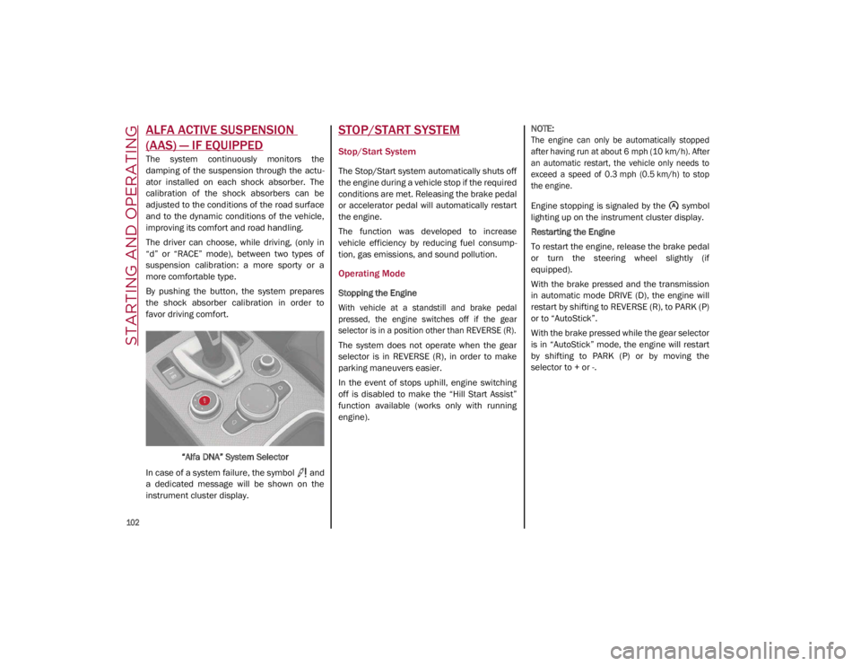
By pushing the button, the system prepares
the shock absorber calibration in order to
favor driving comfort.
“Alfa DNA” System Selector
In case of a system failure, the symbol and
a dedicated message will be shown on the
instrument cluster display.
STOP/START SYSTEM
Stop/Start System
The Stop/Start system automatically shuts off
the engine during a vehicle stop if the required
conditions are met. Releasing the brake pedal
or accelerator pedal will automatically restart
the engine.
The function was developed to increase
vehicle efficiency by reducing fuel consump -
tion, gas emissions, and sound pollution.
Operating Mode
Stopping the Engine
With vehicle at a standstill and brake pedal
pressed, the engine switches off if the gear
selector is in a position other than REVERSE (R).
The system does not operate when the gear
selector is in REVERSE (R), in order to make
parking maneuvers easier.
In the event of stops uphill, engine switching
off is disabled to make the “Hill Start Assist”
function available (works only with running
engine).
NOTE:
The engine can only be automatically stopped
after having run at about 6 mph (10 km/h). After
an automatic restart, the vehicle only needs to
exceed a speed of 0.3 mph (0.5 km/h) to stop
the engine.
Engine stopping is signaled by the symbol
lighting up on the instrument cluster display.
Restarting the Engine
To restart the engine, release the brake pedal
or turn the steering wheel slightly (if
equipped).
With the brake pressed and the transmission
in automatic mode DRIVE (D), the engine will
restart by shifting to REVERSE (R), to PARK (P)
or to “AutoStick”.
With the brake pressed while the gear selector
is in “AutoStick” mode, the engine will restart
by shifting to PARK (P) or by moving the
selector to + or -.
21_GA_OM_EN_USC_t.book Page 102
Page 138 of 284

STARTING AND OPERATING
136
(Continued)
4. When the fuel nozzle “clicks” or shuts off,before removing the nozzle, wait for at
least 10 seconds in order for the fuel to
flow inside the tank.
5. Remove the fuel filler nozzle, tighten the gas cap about a quarter turn until you hear
one click. This is an indication that cap is
properly tightened.
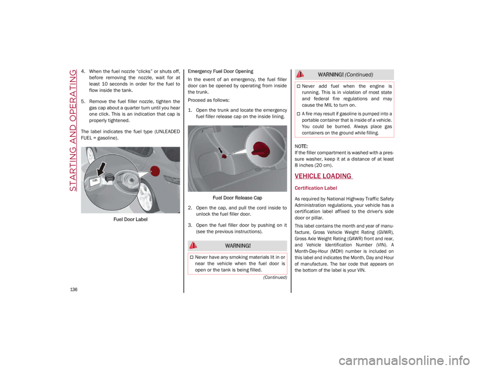
The label indicates the fuel type (UNLEADED
FUEL = gasoline).
Fuel Door Label Emergency Fuel Door Opening
In the event of an emergency, the fuel filler
door can be opened by operating from inside
the trunk.
Proceed as follows:
1. Open the trunk and locate the emergency
fuel filler release cap on the inside lining.
Fuel Door Release Cap
2. Open the cap, and pull the cord inside to unlock the fuel filler door.
3. Open the fuel filler door by pushing on it (see the previous instructions).
NOTE:
If the filler compartment is washed with a pres
-
sure washer, keep it at a distance of at least
8 inches (20 cm).
VEHICLE LOADING
Certification Label
As required by National Highway Traffic Safety
Administration regulations, your vehicle has a
certification label affixed to the driver's side
door or pillar.
This label contains the month and year of manu -
facture, Gross Vehicle Weight Rating (GVWR),
Gross Axle Weight Rating (GAWR) front and rear,
and Vehicle Identification Number (VIN). A
Month-Day-Hour (MDH) number is included on
this label and indicates the Month, Day and Hour
of manufacture. The bar code that appears on
the bottom of the label is your VIN.
WARNING!
Never have any smoking materials lit in or
near the vehicle when the fuel door is
open or the tank is being filled.
Never add fuel when the engine is
running. This is in violation of most state
and federal fire regulations and may
cause the MIL to turn on.
A fire may result if gasoline is pumped into a
portable container that is inside of a vehicle.
You could be burned. Always place gas
containers on the ground while filling.
WARNING! (Continued)
21_GA_OM_EN_USC_t.book Page 136
Page 170 of 284

SAFETY
168
Front Air Bag Operation
Front Air Bags are designed to provide addi-
tional protection by supplementing the seat
belts. Front air bags are not expected to
reduce the risk of injury in rear, side, or roll -
over collisions. The front air bags will not
deploy in all frontal collisions, including some
that may produce substantial vehicle damage
— for example, some pole collisions, truck
underrides, and angle offset collisions.
On the other hand, depending on the type and
location of impact, front air bags may deploy in
crashes with little vehicle front-end damage
but that produce a severe initial deceleration.
Because air bag sensors measure vehicle
deceleration over time, vehicle speed and
damage by themselves are not good indicators
of whether or not an air bag should have
deployed.
Seat belts are necessary for your protection in
all collisions, and also are needed to help keep
you in position, away from an inflating air bag.
When the Occupant Restraint Controller (ORC)
detects a collision requiring the front air bags,
it signals the inflator units. A large quantity of
non-toxic gas is generated to inflate the front
air bags. The steering wheel hub trim cover and the
upper passenger side of the instrument panel
separate and fold out of the way as the air
bags inflate to their full size. The front air bags
fully inflate in less time than it takes to blink
your eyes. The front air bags then quickly
deflate while helping to restrain the driver and
front passenger.
Knee Impact Bolsters
The Knee Impact Bolsters help protect the
knees of the driver and front passenger, and
position the front occupants for improved
interaction with the front air bags.
Supplemental Driver And Front Passenger
Knee Air Bags
This vehicle is equipped with a Supplemental
Driver Knee Air Bag mounted in the instrument
panel below the steering column and a
Supplemental Passenger Knee Air Bag
mounted in the instrument panel below the
glove compartment. The Supplemental Knee
Air Bags provide enhanced protection during a
frontal impact by working together with the
seat belts, pretensioners, and front air bags.
Driver Knee Air Bag
Front Passenger Knee Air Bag
WARNING!
Do not drill, cut, or tamper with the knee
impact bolsters in any way.
Do not mount any accessories to the knee
impact bolsters such as alarm lights,
stereos, citizen band radios, etc.
21_GA_OM_EN_USC_t.book Page 168
Page 231 of 284

229
Types Of Bulbs
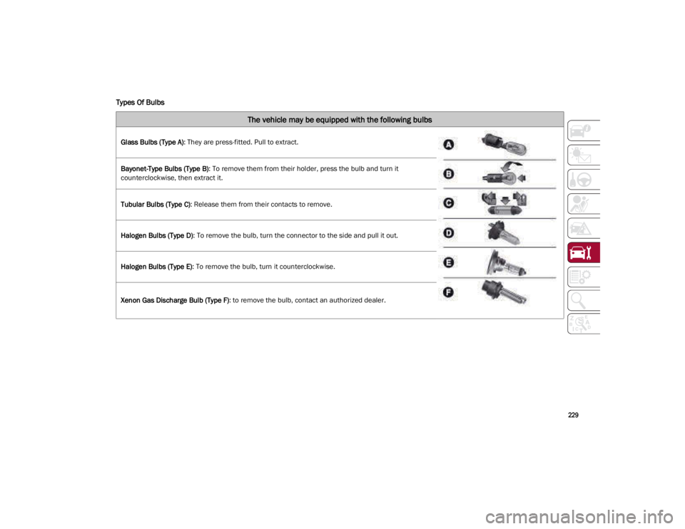
The vehicle may be equipped with the following bulbs
Glass Bulbs (Type A): They are press-fitted. Pull to extract.
Bayonet-Type Bulbs (Type B) : To remove them from their holder, press the bulb and turn it
counterclockwise, then extract it.
Tubular Bulbs (Type C) : Release them from their contacts to remove.
Halogen Bulbs (Type D) : To remove the bulb, turn the connector to the side and pull it out.
Halogen Bulbs (Type E) : To remove the bulb, turn it counterclockwise.
Xenon Gas Discharge Bulb (Type F) : to remove the bulb, contact an authorized dealer.
21_GA_OM_EN_USC_t.book Page 229
Page 232 of 284

SERVICING AND MAINTENANCE
230
Replacement Bulbs
Light bulbsTypePower
Front direction indicatorsPY24W24 W
Rear Fog lights H1155 W
Main beam headlights (Xenon gas discharge) D5S25 W
Main beam headlights (Xenon gas discharge) D3S35 W
Sun visor light 1.5CP2.1 W
Glove compartment light W5W4 W
Trunk lid light W5W5 W
Puddle lights (under door panel) W5W5 W
21_GA_OM_EN_USC_t.book Page 230