2021 ALFA ROMEO GIULIA warning lights
[x] Cancel search: warning lightsPage 93 of 284
91
(Continued)
If, under exceptional circumstances, the use of
the brake is required with the vehicle in motion,
keep the switch on the center console pulled as
long as the brake action is necessary.
The BRAKE warning light may turn on with the
hydraulic system temporarily unavailable; in
this case braking is controlled by the motors.
The brake lights will also automatically turn on
in the same way as for normal braking with the
use of the brake pedal.
Release the switch on the center console to
stop the braking action with the vehicle in
motion.
If, through this procedure, the vehicle is
braked until a speed below 1.9 mph (3 km/h)
is reached and the switch is kept pulled, the
parking brake will definitively engage.
NOTE:
Driving the vehicle with the EPB engaged, or
using it several times to slow down the vehicle,
may cause severe damage to the braking
system.Disengaging The EPB Manually
In order to manually release the parking brake,
the ignition should be in the ACC mode. Press
the brake pedal, and then push the switch on
the center console briefly.
Noise may be heard from the rear of the
vehicle, and a slight movement of the brake
pedal may be detected during disengagement.
After disengaging the Electric Park Brake, the
BRAKE warning light on the instrument panel
and the light on the switch will turn off.
If the BRAKE warning light on the instrument
panel remains on with the EPB disengaged,
this indicates a fault: in this case, contact an
authorized dealer.
WARNING!
Never leave children alone in a vehicle, or
with access to an unlocked vehicle.
Allowing children to be in a vehicle unat
-
tended is dangerous for a number of
reasons. A child or others could be seri -
ously or fatally injured. Children should be
warned not to touch the parking brake,
brake pedal or the gear selector.
Do not leave the key fob in or near the
vehicle or in a location accessible to chil -
dren. A child could operate power windows,
other controls, or move the vehicle.
Be sure the parking brake is fully disen -
gaged before driving; failure to do so can
lead to brake failure and a collision.
Always fully apply the parking brake when
leaving your vehicle, or it may roll and
cause damage or injury.
CAUTION!
Never use gear position PARK (P) instead of
the EPB. Always engage the EPB when
parking the vehicle to prevent injury or
damage caused by the unexpected
movement of the vehicle.
WARNING! (Continued)
21_GA_OM_EN_USC_t.book Page 91
Page 101 of 284
99
ALFA DNA / PRO SELECTOR
Alfa DNA System
This vehicle is equipped with an Alfa DNA
system selector (located on the center
console). There are four modes of operation to
be selected according to driving style and road
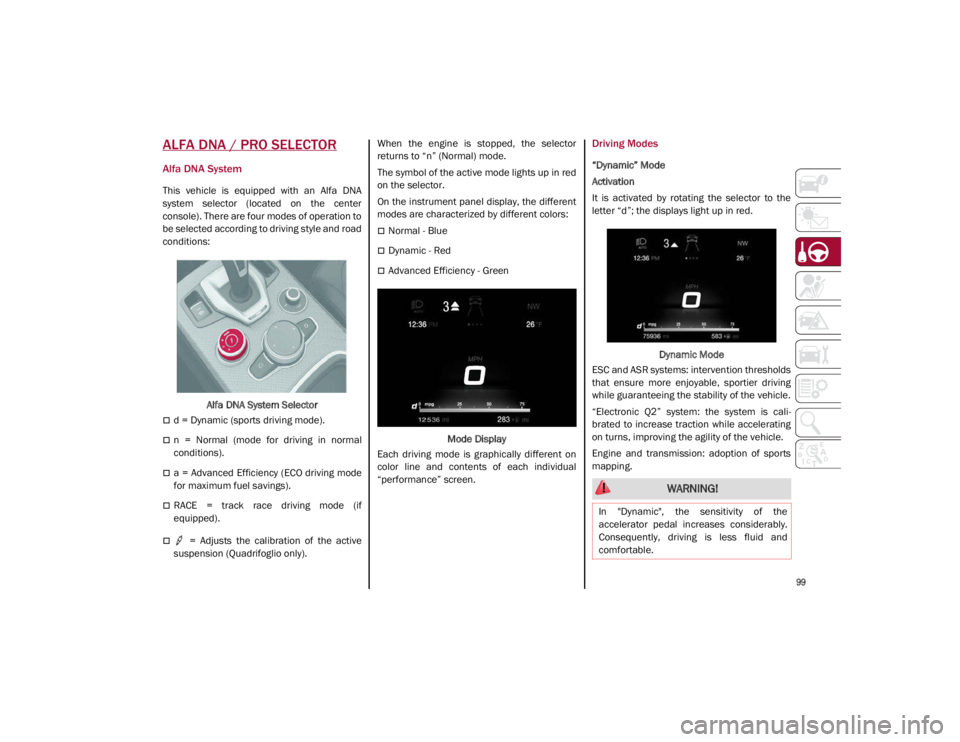
conditions:Alfa DNA System Selector
d = Dynamic (sports driving mode).
n = Normal (mode for driving in normal
conditions).
a = Advanced Efficiency (ECO driving mode
for maximum fuel savings).
RACE = track race driving mode (if
equipped).
= Adjusts the calibration of the active
suspension (Quadrifoglio only). When the engine is stopped, the selector
returns to “n” (Normal) mode.
The symbol of the active mode lights up in red
on the selector.
On the instrument panel display, the different
modes are characterized by different colors:
Normal - Blue
Dynamic - Red
Advanced Efficiency - Green
Mode Display
Each driving mode is graphically different on
color line and contents of each individual
“performance” screen.
Driving Modes
“Dynamic” Mode
Activation
It is activated by rotating the selector to the
letter “d”; the displays light up in red.
Dynamic Mode
ESC and ASR systems: intervention thresholds
that ensure more enjoyable, sportier driving
while guaranteeing the stability of the vehicle.
“Electronic Q2” system: the system is cali -
brated to increase traction while accelerating
on turns, improving the agility of the vehicle.
Engine and transmission: adoption of sports
mapping.
WARNING!
In "Dynamic", the sensitivity of the
accelerator pedal increases considerably.
Consequently, driving is less fluid and
comfortable.
21_GA_OM_EN_USC_t.book Page 99
Page 120 of 284
STARTING AND OPERATING
118
Active System (Hands Removed From The
Steering Wheel For A Short Time)
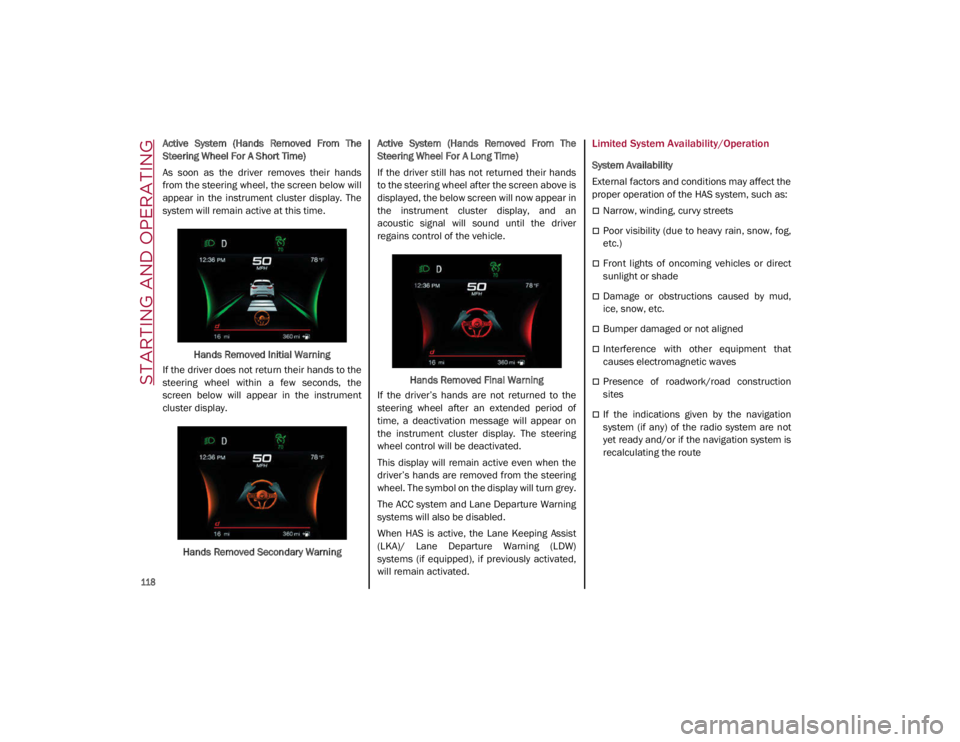
As soon as the driver removes their hands
from the steering wheel, the screen below will
appear in the instrument cluster display. The
system will remain active at this time.Hands Removed Initial Warning
If the driver does not return their hands to the
steering wheel within a few seconds, the
screen below will appear in the instrument
cluster display.
Hands Removed Secondary Warning Active System (Hands Removed From The
Steering Wheel For A Long Time)
If the driver still has not returned their hands
to the steering wheel after the screen above is
displayed, the below screen will now appear in
the instrument cluster display, and an
acoustic signal will sound until the driver
regains control of the vehicle.
Hands Removed Final Warning
If the driver’s hands are not returned to the
steering wheel after an extended period of
time, a deactivation message will appear on
the instrument cluster display. The steering
wheel control will be deactivated.
This display will remain active even when the
driver’s hands are removed from the steering
wheel. The symbol on the display will turn grey.
The ACC system and Lane Departure Warning
systems will also be disabled.
When HAS is active, the Lane Keeping Assist
(LKA)/ Lane Departure Warning (LDW)
systems (if equipped), if previously activated,
will remain activated.Limited System Availability/Operation
System Availability
External factors and conditions may affect the
proper operation of the HAS system, such as:
Narrow, winding, curvy streets
Poor visibility (due to heavy rain, snow, fog,
etc.)
Front lights of oncoming vehicles or direct
sunlight or shade
Damage or obstructions caused by mud,
ice, snow, etc.
Bumper damaged or not aligned
Interference with other equipment that
causes electromagnetic waves
Presence of roadwork/road construction
sites
If the indications given by the navigation
system (if any) of the radio system are not
yet ready and/or if the navigation system is
recalculating the route
21_GA_OM_EN_USC_t.book Page 118
Page 124 of 284

STARTING AND OPERATING
122
When the TJA system is active, the Lane
Keeping Assist (LKA)/Lane Departure Warning
(LDW) systems (if equipped) will be tempo-
rarily disabled. When TJA is not active, the LKA
system
Ú
page 130 and LDW system
Ú
page 128 will remain active.
Limited System Availability/Operation
System Availability
Performance of the TJA system may be
affected by the following factors:
Narrow, winding, curvy streets
Lane boundaries that are not clear or in
conditions of poor visibility (e.g. heavy rain,
snow, fog, etc.)
If the camera is exposed to glare from direct
sunlight or headlights of an oncoming
vehicle
If the camera or sensor is damaged,
covered, or obstructed (e.g. by mud, ice,
snow, etc.)
The bumper is damaged or misaligned
Interference with other equipment causes
electromagnetic waves
Construction sites
If the indications given by the navigation
system of the radio system are not yet ready
or if the system is recalculating System Limited Operation
The TJA system may have limited or reduced
functionality when one of the following condi
-
tions occurs:
Lane boundaries are not clear or in condi -
tions of poor visibility (e.g. in heavy rain,
snow, fog, etc.)
Either the camera or radar are damaged,
covered, or obstructed (e.g. by mud, ice,
snow, etc.)
When driving on hills or narrow bends
Near highway toll booths
When the highway entrance or exit is more
than 20 ft (6 m) wide
If the camera is exposed to glare from
reflections or direct sunlight
NOTE:
If damage to the windshield occurs, have
the windshield replaced by an authorized
dealer as soon as possible.
If the vehicle approaches a bend that is too
narrow with respect to the current speed,
the TJA system will deactivate.
WARNING!
To prevent serious injury or death:
Always remain alert and be ready to take
control of the car in the event that the TJA
system disables.
Always keep your hands on the steering
wheel when the TJA system is activated.
Maintain a safe distance from other vehi -
cles and pay attention to traffic condi -
tions.
The TJA system should only be used as a
driving aid. The drive must always pay
attention to their surroundings when the
system is operating and be ready to take
control of the vehicle at any time.
Do not place any objects on the steering
wheel (e.g. steering wheel covers) that
could interfere with the hand detection
sensor on the steering wheel.
21_GA_OM_EN_USC_t.book Page 122
Page 133 of 284
131
Turning Lane Keeping Assist On Or Off
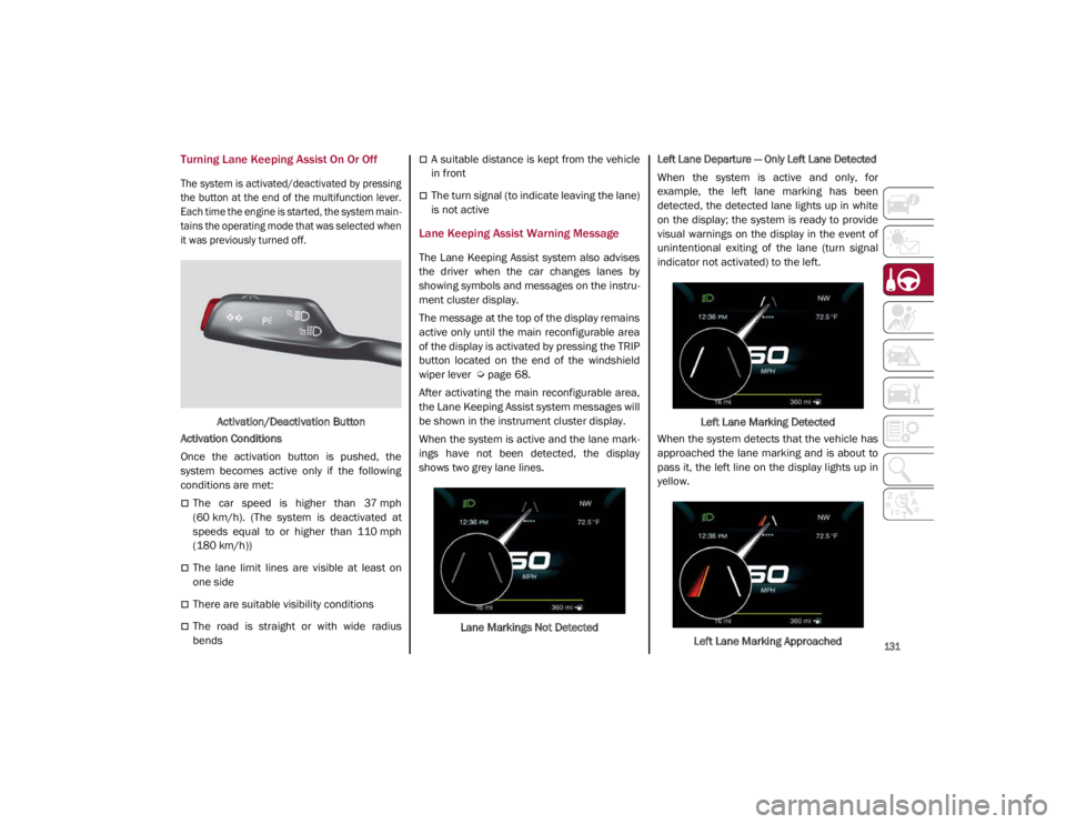
The system is activated/deactivated by pressing
the button at the end of the multifunction lever.
Each time the engine is started, the system main-
tains the operating mode that was selected when
it was previously turned off.
Activation/Deactivation Button
Activation Conditions
Once the activation button is pushed, the
system becomes active only if the following
conditions are met:
The car speed is higher than 37 mph
(60 km/h). (The system is deactivated at
speeds equal to or higher than 110 mph
(180 km/h))
The lane limit lines are visible at least on
one side
There are suitable visibility conditions
The road is straight or with wide radius
bends
A suitable distance is kept from the vehicle
in front
The turn signal (to indicate leaving the lane)
is not active
Lane Keeping Assist Warning Message
The Lane Keeping Assist system also advises
the driver when the car changes lanes by
showing symbols and messages on the instru -
ment cluster display.
The message at the top of the display remains
active only until the main reconfigurable area
of the display is activated by pressing the TRIP
button located on the end of the windshield
wiper lever
Ú
page 68.
After activating the main reconfigurable area,
the Lane Keeping Assist system messages will
be shown in the instrument cluster display.
When the system is active and the lane mark -
ings have not been detected, the display
shows two grey lane lines.
Lane Markings Not Detected
Left Lane Departure — Only Left Lane Detected
When the system is active and only, for
example, the left lane marking has been
detected, the detected lane lights up in white
on the display; the system is ready to provide
visual warnings on the display in the event of
unintentional exiting of the lane (turn signal
indicator not activated) to the left.
Left Lane Marking Detected
When the system detects that the vehicle has
approached the lane marking and is about to
pass it, the left line on the display lights up in
yellow.
Left Lane Marking Approached
21_GA_OM_EN_USC_t.book Page 131
Page 170 of 284

SAFETY
168
Front Air Bag Operation
Front Air Bags are designed to provide addi-
tional protection by supplementing the seat
belts. Front air bags are not expected to
reduce the risk of injury in rear, side, or roll -
over collisions. The front air bags will not
deploy in all frontal collisions, including some
that may produce substantial vehicle damage
— for example, some pole collisions, truck
underrides, and angle offset collisions.
On the other hand, depending on the type and
location of impact, front air bags may deploy in
crashes with little vehicle front-end damage
but that produce a severe initial deceleration.
Because air bag sensors measure vehicle
deceleration over time, vehicle speed and
damage by themselves are not good indicators
of whether or not an air bag should have
deployed.
Seat belts are necessary for your protection in
all collisions, and also are needed to help keep
you in position, away from an inflating air bag.
When the Occupant Restraint Controller (ORC)
detects a collision requiring the front air bags,
it signals the inflator units. A large quantity of
non-toxic gas is generated to inflate the front
air bags. The steering wheel hub trim cover and the
upper passenger side of the instrument panel
separate and fold out of the way as the air
bags inflate to their full size. The front air bags
fully inflate in less time than it takes to blink
your eyes. The front air bags then quickly
deflate while helping to restrain the driver and
front passenger.
Knee Impact Bolsters
The Knee Impact Bolsters help protect the
knees of the driver and front passenger, and
position the front occupants for improved
interaction with the front air bags.
Supplemental Driver And Front Passenger
Knee Air Bags
This vehicle is equipped with a Supplemental
Driver Knee Air Bag mounted in the instrument
panel below the steering column and a
Supplemental Passenger Knee Air Bag
mounted in the instrument panel below the
glove compartment. The Supplemental Knee
Air Bags provide enhanced protection during a
frontal impact by working together with the
seat belts, pretensioners, and front air bags.
Driver Knee Air Bag
Front Passenger Knee Air Bag
WARNING!
Do not drill, cut, or tamper with the knee
impact bolsters in any way.
Do not mount any accessories to the knee
impact bolsters such as alarm lights,
stereos, citizen band radios, etc.
21_GA_OM_EN_USC_t.book Page 168
Page 190 of 284

SAFETY
188
(Continued)
Periodic Safety Checks You Should Make
Outside The Vehicle
Tires
Examine tires for excessive tread wear and
uneven wear patterns. Check for stones, nails,
glass, or other objects lodged in the tread or
sidewall. Inspect the tread for cuts and cracks.
Inspect sidewalls for cuts, cracks, and bulges.
Check the wheel nuts for tightness. Check the
tires (including spare) for proper cold inflation
pressure.
Lights
Have someone observe the operation of brake
lights and exterior lights while you work the
controls. Check turn signal and high beam
indicator lights on the instrument panel.
Door Latches
Check for proper closing, latching, and locking.
Fluid Leaks
Check area under the vehicle after overnight
parking for fuel, coolant, oil, or other fluid
leaks. Also, if gasoline fumes are detected or if
fuel or brake fluid leaks are suspected the
cause should be located and corrected imme-
diately.
ALWAYS REMOVE THE EXISTING FLOOR
MAT FROM THE VEHICLE before
installing any other floor mat. NEVER
install or stack an additional floor mat on
top of an existing floor mat.
ONLY install floor mats designed to fit your
vehicle. NEVER install a floor mat that
cannot be properly attached and secured
to your vehicle. If a floor mat needs to be
replaced, only use a FCA approved floor
mat for the specific make, model, and
year of your vehicle.
ONLY use the driver’s side floor mat on the
driver’s side floor area. To check for inter -
ference, with the vehicle properly parked
with the engine off, fully depress the
accelerator, the brake, and the clutch
pedal (if present) to check for interfer -
ence. If your floor mat interferes with the
operation of any pedal, or is not secure to
the floor, remove the floor mat from the
vehicle and place the floor mat in your
trunk.
ONLY use the passenger’s side floor mat
on the passenger’s side floor area.
WARNING! (Continued)
ALWAYS make sure objects cannot fall or
slide into the driver’s side floor area when
the vehicle is moving. Objects can become
trapped under accelerator, brake, or
clutch pedals and could cause a loss of
vehicle control.
NEVER place any objects under the floor
mat (e.g., towels, keys, etc.). These
objects could change the position of the
floor mat and may cause interference with
the accelerator, brake, or clutch pedals.
If the vehicle carpet has been removed
and re-installed, always properly attach
carpet to the floor and check the floor mat
fasteners are secure to the vehicle carpet.
Fully depress each pedal to check for
interference with the accelerator, brake,
or clutch pedals then re-install the floor
mats.
It is recommended to only use mild soap
and water to clean your floor mats. After
cleaning, always check your floor mat has
been properly installed and is secured to
your vehicle using the floor mat fasteners
by lightly pulling mat.
WARNING! (Continued)
21_GA_OM_EN_USC_t.book Page 188
Page 199 of 284
197
12. Apply the adhesive label from the sealantbottle where it can be easily seen by the
driver as a reminder that the tire has been
treated with a Tire Service Kit, as well as
not to exceed the speed restriction for the
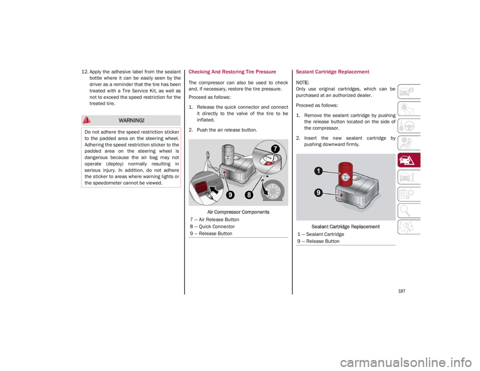
treated tire.Checking And Restoring Tire Pressure
The compressor can also be used to check
and, if necessary, restore the tire pressure.
Proceed as follows:
1. Release the quick connector and connectit directly to the valve of the tire to be
inflated.
2. Push the air release button.
Air Compressor Components
Sealant Cartridge Replacement
NOTE:
Only use original cartridges, which can be
purchased at an authorized dealer.
Proceed as follows:
1. Remove the sealant cartridge by pushingthe release button located on the side of
the compressor.
2. Insert the new sealant cartridge by pushing downward firmly.
Sealant Cartridge Replacement
WARNING!
Do not adhere the speed restriction sticker
to the padded area on the steering wheel.
Adhering the speed restriction sticker to the
padded area on the steering wheel is
dangerous because the air bag may not
operate (deploy) normally resulting in
serious injury. In addition, do not adhere
the sticker to areas where warning lights or
the speedometer cannot be viewed.
7 — Air Release Button
8 — Quick Connector
9 — Release Button
1 — Sealant Cartridge
9 — Release Button
21_GA_OM_EN_USC_t.book Page 197