2021 ALFA ROMEO GIULIA tires
[x] Cancel search: tiresPage 158 of 284

SAFETY
156
(Continued)
Vehicles Traveling At Right Angles To The
Vehicle
The system may temporarily react to a vehicle
that is passing through the radar sensor’s
operating range at right angles.Other Vehicle Passing Through Radar RangeTire Pressure Monitoring System (TPMS)
The vehicle is equipped with a TPMS that
sends the inflation pressure information of
each tire to the control unit, and will signal the
driver in the event of insufficient tire pressure.
The TPMS uses wireless technology with wheel
rim mounted electronic sensors to monitor tire
pressure levels. Sensors, mounted to each
wheel as part of the valve stem, transmit tire
pressure readings to the receiver module.
Tire pressure will vary with temperature by
approximately 1 psi (7 kPa) for every 12°F
(6.5°C). This means that when the outside
temperature decreases, the tire pressure will
also decrease. Tire pressure should always be
set based on cold inflation tire pressure. This
is defined as the tire pressure after the vehicle
has not been driven for at least three hours, or
driven less than 1 mile (1.6 km) after a three
hour period. The cold tire inflation pressure
must not exceed the maximum inflation pres -
sure molded into the tire sidewall. The tire
pressure will also increase as the vehicle is
driven. This is normal, and there should be no
adjustment for this increased pressure. See
Ú
page 234 for information on how to properly
inflate the vehicle’s tires.
The TPMS will signal the driver if pressure falls
below the warning limit for any reason,
including the effects of low temperature and
normal loss of pressure from the tire.
WARNING!
The system has not been designed to
prevent impacts and cannot detect
possible conditions leading to an accident
in advance. Failure to take into account
this warning may lead to serious or fatal
injuries.
The system may activate, assessing the
trajectory of the vehicle, for the presence
of reflecting metal objects different from
other vehicles, such as safety barriers,
road signs, barriers before parking lots,
tollgates, level crossings, gates, railways,
objects near road constructions sites or
higher than the vehicle (e.g. a fly-over). In
the same way, the system may intervene
inside multi-story parking lots or tunnels,
or due to a glare on the road surface.
These possible activations are a conse -
quence of the real driving scenario
coverage by the system and must not be
regarded as faults.
The system has been designed for road
use only. If the vehicle is driven on a track,
the system must be deactivated to avoid
unnecessary warnings. Automatic deacti -
vation is signaled by the dedicated
warning light/symbol switching on in the
instrument panel
Ú
page 73.
WARNING! (Continued)
21_GA_OM_EN_USC_t.book Page 156
Page 159 of 284

157
The TPMS will stop indicating insufficient tire
pressure when pressure is equal to or greater
than the prescribed cold inflation level. There-
fore, if insufficient tire pressure is indicated by
the ( ) warning light displaying in the instru -
ment cluster, increase the inflation pressure
up to the prescribed cold inflation value.
The system will automatically update, and the
Tire Pressure Monitoring System Warning
Light will turn off once the system receives the
updated tire pressures. The vehicle may need
to be driven for up to 20 minutes above
15 mph (24 km/h) in order for the TPMS to
receive this information.
NOTE:
The TPMS cannot indicate sudden tire pres -
sure drops (e.g. if a tire bursts). In this case,
proceed with caution and avoid abrupt
steering.
Operating Example
For example, your vehicle may have a
recommended cold (parked for more than three
hours) placard pressure of 33 psi (227 kPa). If the
ambient temperature is 68°F (20°C), and the
measured tire pressure is 28 psi (193 kPa), a
temperature drop to 20°F (-7°C) will decrease the
tire pressure to approximately 24 psi (165 kPa).
This tire pressure is low enough to turn on the Tire
Pressure Monitoring System Warning Light. Driving
the vehicle may cause the tire pressure to rise to
approximately 28 psi (193 kPa), but the Tire
Pressure Monitoring System Warning Light will still
be on. In this situation, the Tire Pressure Monitoring System Warning Light will turn off only after the tires
are inflated to the vehicle’s recommended cold
placard pressure value.
Insufficient Tire Pressure Indication
If an insufficient pressure value is detected on
one or more tires, the Warning Light in the
instrument cluster will display alongside the
dedicated messages, the system will highlight
the tire or tires with insufficient pressure
graphically, and an acoustic signal will be
emitted.
In this case, stop the vehicle, check the infla
-
tion pressure of each tire, and inflate the
necessary tire or tires to the correct cold infla -
tion pressure value, shown on the display or in
the dedicated TPMS menu.
CAUTION!
The TPMS has been optimized for the orig -
inal equipment tires and wheels. TPMS
pressures and warning have been estab -
lished for the tire size equipped on your
vehicle. Undesirable system operation or
sensor damage may result when using
replacement equipment that is not of the
same size, type, and/or style. The TPMS
sensor is not designed for use on after -
market wheels and may contribute to a
poor overall system performance or
sensor damage. Customers are encour -
aged to use Original Equipment Manufac -
turer (OEM) wheels to assure proper TPMS
feature operation.
Using aftermarket tire sealants may cause
the Tire Pressure Monitoring System
(TPMS) sensor to become inoperable.
After using an aftermarket tire sealant it is
recommended that you take your vehicle
to an authorized dealer to have your
sensor function checked.
After inspecting or adjusting the tire pres -
sure always reinstall the valve stem cap.
This will prevent moisture and dirt from
entering the valve stem, which could
damage the TPMS sensor.
21_GA_OM_EN_USC_t.book Page 157
Page 160 of 284

SAFETY
158
TPMS Temporarily Disabled:
TPMS Check Message
When a system fault is detected, the Tire Pres-
sure Monitoring System Warning Light will
flash on and off for 75 seconds, and then
remain on solid. The system fault will also
sound a chime. If the ignition is cycled, this
sequence will repeat, provided that the system
fault still exists. The Tire Pressure Monitoring
System Warning Light will turn off when the
fault condition no longer exists. A system fault
can occur due to any of the following:
Jamming due to electronic devices or
driving next to facilities emitting the same
radio frequencies as the TPMS sensors.
Installing some form of aftermarket window
tinting that affects radio wave signals.
Packed snow or ice around the wheels or
wheel housings.
Using tire chains on the vehicle.
Using wheels/tires not equipped with TPMS
sensors.
After the punctured tire has been repaired
with the original tire sealant contained in the
Tire Kit, the previous condition must be
restored so that the Warning Light is off
during normal driving. TPMS Deactivation
The TPMS can be deactivated by replacing all
four wheel and tire assemblies (road tires)
with wheel and tire assemblies that do not
have TPMS sensors, such as when installing
winter wheel and tire assemblies on your
vehicle.
To deactivate the TPMS, first replace all four
wheel and tire assemblies (road tires) with
tires not equipped with Tire Pressure Moni
-
toring System sensors. Then, drive the vehicle
for 20 minutes above 15 mph (24 km/h). The
TPMS will chime, the TPMS Warning Light will
flash on and off for 75 seconds and then
remain on. The instrument cluster will display
the “SERVICE TPM SYSTEM” message and
then display dashes (--) in place of the pres -
sure values.
Beginning with the next ignition switch cycle,
the TPMS will no longer chime or display the
“SERVICE TPM SYSTEM” message in the
instrument cluster. Instead, dashes (--) will
remain in place of the pressure values.
To reactivate the TPMS, replace all four wheel
and tire assemblies (road tires) with tires
equipped with TPMS sensors. Then, drive the
vehicle for up to 20 minutes above 15 mph
(24 km/h). The TPMS will chime, the TPMS
Warning Light will flash on and off for 75
seconds and then turn off. The instrument cluster will display the “SERVICE TPM
SYSTEM” message and then display pressure
values in place of the dashes. On the next igni
-
tion switch cycle the "SERVICE TPM SYSTEM"
message will no longer be displayed, as long
as no system fault exists.
NOTE:
The TPMS is not intended to replace normal
tire care and maintenance, or to provide
warning of a tire failure or condition.
The TPMS should not be used as a tire pres -
sure gauge while adjusting your tire pressure.
Driving on a significantly underinflated tire will
cause the tire to overheat, and can lead to tire
failure. Underinflation also reduces fuel effi -
ciency and tire tread life, and may affect the
vehicle’s handling and stopping ability.
The TPMS is not a substitute for proper tire
maintenance, and it is the driver’s responsi -
bility to maintain correct tire pressure using
an accurate tire pressure gauge, even if
underinflation has not reached the level to
trigger illumination of the Tire Pressure
Monitoring System Warning Light.
Seasonal temperature changes will affect
tire pressure, and the TPMS will monitor the
actual tire pressure in the tire
Ú
page 273.
21_GA_OM_EN_USC_t.book Page 158
Page 190 of 284

SAFETY
188
(Continued)
Periodic Safety Checks You Should Make
Outside The Vehicle
Tires
Examine tires for excessive tread wear and
uneven wear patterns. Check for stones, nails,
glass, or other objects lodged in the tread or
sidewall. Inspect the tread for cuts and cracks.
Inspect sidewalls for cuts, cracks, and bulges.
Check the wheel nuts for tightness. Check the
tires (including spare) for proper cold inflation
pressure.
Lights
Have someone observe the operation of brake
lights and exterior lights while you work the
controls. Check turn signal and high beam
indicator lights on the instrument panel.
Door Latches
Check for proper closing, latching, and locking.
Fluid Leaks
Check area under the vehicle after overnight
parking for fuel, coolant, oil, or other fluid
leaks. Also, if gasoline fumes are detected or if
fuel or brake fluid leaks are suspected the
cause should be located and corrected imme-
diately.
ALWAYS REMOVE THE EXISTING FLOOR
MAT FROM THE VEHICLE before
installing any other floor mat. NEVER
install or stack an additional floor mat on
top of an existing floor mat.
ONLY install floor mats designed to fit your
vehicle. NEVER install a floor mat that
cannot be properly attached and secured
to your vehicle. If a floor mat needs to be
replaced, only use a FCA approved floor
mat for the specific make, model, and
year of your vehicle.
ONLY use the driver’s side floor mat on the
driver’s side floor area. To check for inter -
ference, with the vehicle properly parked
with the engine off, fully depress the
accelerator, the brake, and the clutch
pedal (if present) to check for interfer -
ence. If your floor mat interferes with the
operation of any pedal, or is not secure to
the floor, remove the floor mat from the
vehicle and place the floor mat in your
trunk.
ONLY use the passenger’s side floor mat
on the passenger’s side floor area.
WARNING! (Continued)
ALWAYS make sure objects cannot fall or
slide into the driver’s side floor area when
the vehicle is moving. Objects can become
trapped under accelerator, brake, or
clutch pedals and could cause a loss of
vehicle control.
NEVER place any objects under the floor
mat (e.g., towels, keys, etc.). These
objects could change the position of the
floor mat and may cause interference with
the accelerator, brake, or clutch pedals.
If the vehicle carpet has been removed
and re-installed, always properly attach
carpet to the floor and check the floor mat
fasteners are secure to the vehicle carpet.
Fully depress each pedal to check for
interference with the accelerator, brake,
or clutch pedals then re-install the floor
mats.
It is recommended to only use mild soap
and water to clean your floor mats. After
cleaning, always check your floor mat has
been properly installed and is secured to
your vehicle using the floor mat fasteners
by lightly pulling mat.
WARNING! (Continued)
21_GA_OM_EN_USC_t.book Page 188
Page 236 of 284

SERVICING AND MAINTENANCE
234
TIRES
Tire Safety Information
Tire safety information will cover aspects of
the following information: Tire Markings, Tire
Identification Numbers, Tire Terminology and
Definitions, Tire Pressures, and Tire Loading.
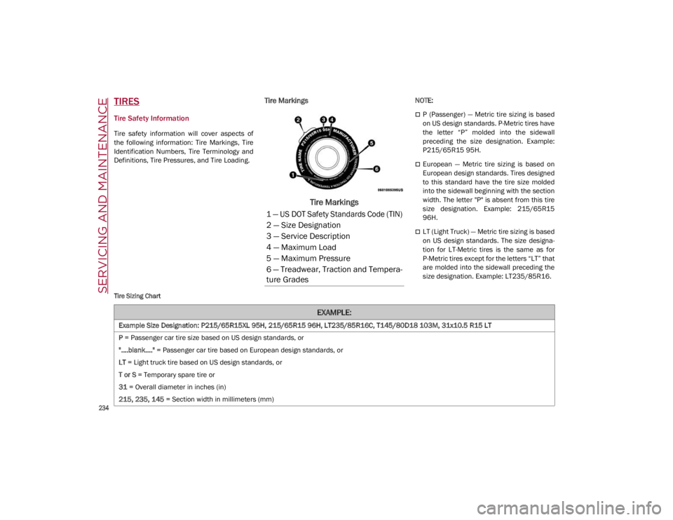
Tire Markings
Tire Markings
NOTE:
P (Passenger) — Metric tire sizing is based
on US design standards. P-Metric tires have
the letter “P” molded into the sidewall
preceding the size designation. Example:
P215/65R15 95H.
European — Metric tire sizing is based on
European design standards. Tires designed
to this standard have the tire size molded
into the sidewall beginning with the section
width. The letter "P" is absent from this tire
size designation. Example: 215/65R15
96H.
LT (Light Truck) — Metric tire sizing is based
on US design standards. The size designa-
tion for LT-Metric tires is the same as for
P-Metric tires except for the letters “LT” that
are molded into the sidewall preceding the
size designation. Example: LT235/85R16.
Tire Sizing Chart
1 — US DOT Safety Standards Code (TIN)
2 — Size Designation
3 — Service Description
4 — Maximum Load
5 — Maximum Pressure
6 — Treadwear, Traction and Tempera -
ture Grades
EXAMPLE:
Example Size Designation: P215/65R15XL 95H, 215/65R15 96H, LT235/85R16C, T145/80D18 103M, 31x10.5 R15 LT
P = Passenger car tire size based on US design standards, or
"....blank...." = Passenger car tire based on European design standards, or
LT = Light truck tire based on US design standards, or
T or S = Temporary spare tire or
31 = Overall diameter in inches (in)
215, 235, 145 = Section width in millimeters (mm)
21_GA_OM_EN_USC_t.book Page 234
Page 238 of 284

SERVICING AND MAINTENANCE
236
Tire Identification Number (TIN)
The TIN may be found on one or both sides of the tire; however, the date code may only be on one side. Tires with white sidewalls will have the full
TIN, including the date code, located on the white sidewall side of the tire. Look for the TIN on the outboard side of black sidewall tires as mounted
on the vehicle. If the TIN is not found on the outboard side, then you will find it on the inboard side of the tire.
EXAMPLE:
DOT MA L9 ABCD 0301
DOT = Department of Transportation
This symbol certifies that the tire is in compliance with the US Department of Transportation tire safety standards and is approved for highway use
MA = Code representing the tire manufacturing location (two digits)
L9 = Code representing the tire size (two digits)
ABCD = Code used by the tire manufacturer (one to four digits)
03 = Number representing the week in which the tire was manufactured (two digits)
03 means the 3rd week
01 = Number representing the year in which the tire was manufactured (two digits)
01 means the year 2001
Prior to July 2000, tire manufacturers were only required to have one number to represent the year in which the tire was manufactured.
Example: 031 could represent the 3rd week of 1981 or 1991
21_GA_OM_EN_USC_t.book Page 236
Page 240 of 284

SERVICING AND MAINTENANCE
238
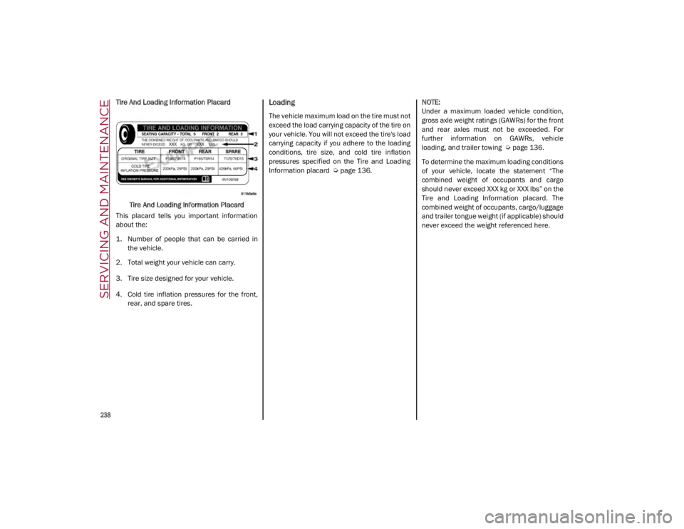
Tire And Loading Information PlacardTire And Loading Information Placard
This placard tells you important information
about the:
1. Number of people that can be carried in the vehicle.
2. Total weight your vehicle can carry.
3. Tire size designed for your vehicle.
4. Cold tire inflation pressures for the front, rear, and spare tires.Loading
The vehicle maximum load on the tire must not
exceed the load carrying capacity of the tire on
your vehicle. You will not exceed the tire's load
carrying capacity if you adhere to the loading
conditions, tire size, and cold tire inflation
pressures specified on the Tire and Loading
Information placard
Ú
page 136.
NOTE:
Under a maximum loaded vehicle condition,
gross axle weight ratings (GAWRs) for the front
and rear axles must not be exceeded. For
further information on GAWRs, vehicle
loading, and trailer towing
Ú
page 136.
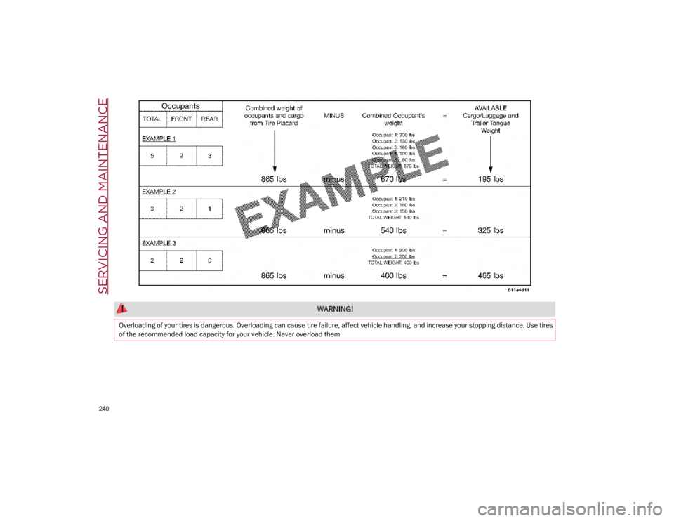
To determine the maximum loading conditions
of your vehicle, locate the statement “The
combined weight of occupants and cargo
should never exceed XXX kg or XXX lbs” on the
Tire and Loading Information placard. The
combined weight of occupants, cargo/luggage
and trailer tongue weight (if applicable) should
never exceed the weight referenced here.
21_GA_OM_EN_USC_t.book Page 238
Page 242 of 284

SERVICING AND MAINTENANCE
240
WARNING!
Overloading of your tires is dangerous. Overloading can cause tire failure, affect vehicle handling, and increase your stopping distance. Use tires
of the recommended load capacity for your vehicle. Never overload them.
21_GA_OM_EN_USC_t.book Page 240