2020 YAMAHA XSR 900 ESP
[x] Cancel search: ESPPage 8 of 102

1-1
1
2
3
4
5
6
7
8
9
10
11
12
Safety information
EAU1028C
Be a Responsible Owner
As the vehicle’s owner, you are respon-
sible for the safe and proper operation
of your motorcycle.
Motorcycles are single-track vehicles.
Their safe use and operation are de-
pendent upon the use of proper riding
techniques as well as the expertise of
the operator. Every operator should
know the following requirements before
riding this motorcycle.
He or she should:
Obtain thorough instructions from
a competent source on all aspects
of motorcycle operation.
Observe the warnings and mainte-
nance requirements in this Own-
er’s Manual.
Obtain qualified training in safe
and proper riding techniques.
Obtain professional technical ser-
vice as indicated in this Owner’s
Manual and/or when made neces-
sary by mechanical conditions.
Never operate a motorcycle with-
out proper training or instruction. Take a training course. Beginners
should receive training from a cer-
tified instructor. Contact an autho-
rized motorcycle dealer to find out
about the training courses nearest
you.
Safe Riding
Perform the pre-operation checks each
time you use the vehicle to make sure it
is in safe operating condition. Failure to
inspect or maintain the vehicle properly
increases the possibility of an accident
or equipment damage. See page 4-1
for a list of pre-operation checks.
This motorcycle is designed to car-
ry the operator and a passenger.
The failure of motorists to detect
and recognize motorcycles in traf-
fic is the predominating cause of
automobile/motorcycle accidents.
Many accidents have been caused
by an automobile driver who did
not see the motorcycle. Making
yourself conspicuous appears to
be very effective in reducing the
chance of this type of accident.
Therefore:
Wear a brightly colored jacket. Use extra caution when you are
approaching and passing
through intersections, since in-
tersections are the most likely
places for motorcycle accidents
to occur.
Ride where other motorists can see you. Avoid riding in another
motorist’s blind spot.
Never maintain a motorcycle without proper knowledge. Con-
tact an authorized motorcycle
dealer to inform you on basic
motorcycle maintenance. Cer-
tain maintenance can only be
carried out by certified staff.
Many accidents involve inexperi-
enced operators. In fact, many op-
erators who have been involved in
accidents do not even have a cur-
rent motorcycle license.
Make sure that you are qualifiedand that you only lend your mo-
torcycle to other qualified opera-
tors.
Know your skills and limits. Staying within your limits may
help you to avoid an accident.
We recommend that you prac-
BAE-28199-E1.book 1 ページ 2019年8月23日 金曜日 午後3時56分
Page 11 of 102

Safety information
1-4
12
3
4
5
6
7
8
9
10
11
12
dorse nor recommend the use of ac-
cessories not sold by Yamaha or
modifications not specifically recom-
mended by Yamaha, even if sold and
installed by a Yamaha dealer.
Aftermarket Parts, Accessories,
and Modifications
While you may find aftermarket prod-
ucts similar in design and quality to
genuine Yamaha accessories, recog-
nize that some aftermarket accessories
or modifications are not suitable be-
cause of potential safety hazards to you
or others. Installing aftermarket prod-
ucts or having other modifications per-
formed to your vehicle that change any
of the vehicle’s design or operation
characteristics can put you and others
at greater risk of serious injury or death.
You are responsible for injuries related
to changes in the vehicle.
Keep the following guidelines in mind,
as well as those provided under “Load-
ing” when mounting accessories.
Never install accessories or carry
cargo that would impair the perfor-
mance of your motorcycle. Care-
fully inspect the accessory before using it to make sure that it does
not in any way reduce ground
clearance or cornering clearance,
limit suspension travel, steering
travel or control operation, or ob-
scure lights or reflectors.
Accessories fitted to the handle-
bar or the front fork area can
create instability due to improper
weight distribution or aerody-
namic changes. If accessories
are added to the handlebar or
front fork area, they must be as
lightweight as possible and
should be kept to a minimum.
Bulky or large accessories may seriously affect the stability of
the motorcycle due to aerody-
namic effects. Wind may at-
tempt to lift the motorcycle, or
the motorcycle may become un-
stable in cross winds. These ac-
cessories may also cause
instability when passing or being
passed by large vehicles.
Certain accessories can dis- place the operator from his or
her normal riding position. This
improper position limits the free- dom of movement of the opera-
tor and may limit control ability,
therefore, such accessories are
not recommended.
Use caution when adding electri-
cal accessories. If electrical acces-
sories exceed the capacity of the
motorcycle’s electrical system, an
electric failure could result, which
could cause a dangerous loss of
lights or engine power.
Aftermarket Tires and Rims
The tires and rims that came with your
motorcycle were designed to match the
performance capabilities and to provide
the best combination of handling, brak-
ing, and comfort. Other tires, rims, siz-
es, and combinations may not be
appropriate. See page 6-16 for tire
specifications and for information on
servicing and replacing your tires.
Transporting the Motorcycle
Be sure to observe following instruc-
tions before transporting the motorcy-
cle in another vehicle.
Remove all loose items from the
motorcycle.
BAE-28199-E1.book 4 ページ 2019年8月23日 金曜日 午後3時56分
Page 18 of 102

Instrument and control functions
3-3
1
23
4
5
6
7
8
9
10
11
12 To unlock the steering
From the “LOCK” position, push the
key in and turn it to “OFF”.
EAU59681
(Parking)
The hazard lights and turn signal lights
can be turned on, but all other electrical
systems are off. The key can be re-
moved.NOTICE
ECA20760
Using the hazard or turn signal
lights for an extended length of timemay cause the battery to discharge.
EAU4939H
Indicator lights and warning
lights
EAU11032
Turn signal indicator lights “ ” and
“”
Each indicator light will flash when its
corresponding turn signal lights are flashing.
EAU11061
Neutral indicator light “ ”
This indicator light comes on when the
transmission is in the neutral position.
EAU11081
High beam indicator light “ ”
This indicator light comes on when the
high beam of the headlight is switched
on.
EAU11259
Oil level warning light “ ”
This warning light comes on when the
engine oil level is low. To prevent en-
gine damage, replenish the engine oil
as soon as possible.
Even if the oil level is sufficient, the
warning light may flicker when riding on
a slope or during sudden acceleration
or deceleration, but this is not a mal-
function. If a problem is detected in the
oil level detection circuit, the oil level
warning light will flash repeatedly. If this
occurs, have a Yamaha dealer check
the vehicle.
1. Push.
2. Turn.12
1. Traction control system indicator light
“”
2. ABS warning light “ ”
3. Engine trouble warning light “ ”
4. Coolant temperature warning light “ ”
5. Oil level warning light “ ”
6. Left turn signal indicator light “ ”
7. Neutral indicator light “ ”
8. High beam indicator light “ ”
9. Right turn signal indicator light “ ”
10.Immobilizer system indicator light “ ”
2
13
4
5
6
7
8
9
10
ABS
BAE-28199-E1.book 3 ページ 2019年8月23日 金曜日 午後3時56分
Page 22 of 102

Instrument and control functions
3-7
1
23
4
5
6
7
8
9
10
11
12 Fuel meter
The fuel meter indicates the amount of
fuel in the fuel tank. The display seg-
ments of the fuel meter disappear from
“F” (full tank) towards “E” (empty tank)
as the fuel level decreases. When the
last segment and frame start flashing,
refuel as soon as possible.
TIPIf a problem is detected in the fuel tank
electrical circuit, the fuel level seg-
ments, frame, and “ ” will flash repeat-
edly. Have a Yamaha dealer check thevehicle.
Eco indicator
This indicator comes on when the vehi-
cle is being operated in an environmen-
tally friendly, fuel-efficient manner. The
indicator goes off when the vehicle is
stopped.
TIPConsider the following tips to reduce
fuel consumption:
Avoid high engine speeds during
acceleration.
Travel at a constant speed.
Select the transmission gear that
is appropriate for the vehiclespeed.Transmission gear display
This display shows the selected gear.
The neutral position is indicated by “ ”
and by the neutral indicator light.
Drive mode display
1. Frame
2. Segment1
2
1. Eco indicator “ECO”
1
1. Neutral indicator light “ ”
2. Transmission gear display
1. Drive mode display12
1
BAE-28199-E1.book 7 ページ 2019年8月23日 金曜日 午後3時56分
Page 27 of 102

Instrument and control functions
3-12
1
234
5
6
7
8
9
10
11
12
EAU47636
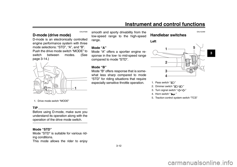
D-mode (drive mode)D-mode is an electronically controlled
engine performance system with three
mode selections: “STD”, “A”, and “B”.
Push the drive mode switch “MODE” to
switch between modes. (See
page 3-14.)TIPBefore using D-mode, make sure you
understand its operation along with theoperation of the drive mode switch.
Mode “STD”
Mode “STD” is suitable for various rid-
ing conditions.
This mode allows the rider to enjoy smooth and sporty drivability from the
low-speed range to the high-speed
range.
Mode “A”
Mode “A” offers a sportier engine re-
sponse in the low- to mid-speed range
compared to mode “STD”.
Mode “B”
Mode “B” offers response that is some-
what less sharp compared to mode
“STD” for riding situations that require
especially sensitive throttle operation.
EAU1234M
Handlebar switchesLeft
1. Drive mode switch “MODE”
1
1. Pass switch “ ”
2. Dimmer switch “ / ”
3. Turn signal switch “ / ”
4. Horn switch “ ”
5. Traction control system switch “TCS”
2341
5
BAE-28199-E1.book 12 ページ 2019年8月23日 金曜日 午後3時56分
Page 31 of 102

Instrument and control functions
3-16
1
234
5
6
7
8
9
10
11
12
TIP
The ABS performs a self-diagno-
sis test each time the vehicle first
starts off after the key is turned to
“ON” and the vehicle has traveled
at a speed of 10 km/h (6 mi/h) or
higher. During this test, a “clicking”
noise can be heard from the hy-
draulic control unit, and if the brake
lever or brake pedal is even slight-
ly applied, a vibration can be felt at
the lever and pedal, but these do
not indicate a malfunction.
This ABS has a test mode which
allows the owner to experience the
pulsation at the brake lever or
brake pedal when the ABS is oper-
ating. However, special tools are
required, so please consult yourYamaha dealer.
NOTICE
ECA20100
Be careful not to damage the wheel
sensor or wheel sensor rotor; other-
wise, improper performance of theABS will result.
EAU74351
Traction control systemThe traction control system (TCS)
helps maintain traction when accelerat-
ing on slippery surfaces, such as un-
paved or wet roads. If sensors detect
that the rear wheel is starting to slip (un-
controlled spinning), the traction control
system assists by regulating engine
power as needed until traction is re-
stored.
WARNING
EWA15433
The traction control system is not a
substitute for riding appropriately
for the conditions. Traction control
cannot prevent loss of traction due
to excessive speed when entering
turns, when accelerating hard at a
sharp lean angle, or while braking,
and cannot prevent front wheel slip-
ping. As with any vehicle, approach
surfaces that may be slippery with
caution and avoid especially slip-pery surfaces.
The “ ” indicator light flashes when
traction control has engaged. You may
notice slight changes in engine and ex-
1. Front wheel sensor
2. Front wheel sensor rotor
1. Rear wheel sensor
2. Rear wheel sensor rotor
1
2
12
BAE-28199-E1.book 16 ページ 2019年8月23日 金曜日 午後3時56分
Page 41 of 102

Instrument and control functions
3-26
1
234
5
6
7
8
9
10
11
12
EAU70641
Auxiliary DC connectorThis vehicle is equipped with an auxilia-
ry DC connector. Consult your Yamaha
dealer before installing any accesso-
ries.
EAU15306
SidestandThe sidestand is located on the left side
of the frame. Raise the sidestand or
lower it with your foot while holding the
vehicle upright.TIPThe built-in sidestand switch is part of
the ignition circuit cut-off system, which
cuts the ignition in certain situations.
(See the following section for an expla-
nation of the ignition circuit cut-off sys-tem.)
WARNING
EWA10242
The vehicle must not be ridden with
the sidestand down, or if the sides-
tand cannot be properly moved up
(or does not stay up), otherwise the
sidestand could contact the ground
and distract the operator, resulting
in a possible loss of control.
Yamaha’s ignition circuit cut-off
system has been designed to assist
the operator in fulfilling the respon-
sibility of raising the sidestand be-
fore starting off. Therefore, check
this system regularly and have a Yamaha dealer repair it if it does not
function properly.
BAE-28199-E1.book 26 ページ 2019年8月23日 金曜日 午後3時56分
Page 74 of 102

Periodic maintenance and adjustment
6-24
1
2
3
4
56
7
8
9
10
11
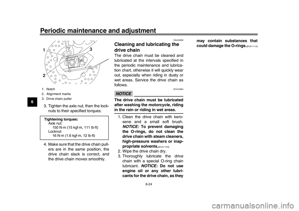
12 3. Tighten the axle nut, then the lock-
nuts to their specified torques.
4. Make sure that the drive chain pull- ers are in the same position, the
drive chain slack is correct, and
the drive chain moves smoothly.
EAU23026
Cleaning and lubricating the
drive chainThe drive chain must be cleaned and
lubricated at the intervals specified in
the periodic maintenance and lubrica-
tion chart, otherwise it will quickly wear
out, especially when riding in dusty or
wet areas. Service the drive chain as
follows.NOTICE
ECA10584
The drive chain must be lubricated
after washing the motorcycle, ridingin the rain or riding in wet areas.
1. Clean the drive chain with kero- sene and a small soft brush.
NOTICE: To prevent damaging
the O-rings, do not clean the
drive chain with steam cleaners,
high-pressure washers or inap-
propriate solvents.
[ECA11122]
2. Wipe the drive chain dry.
3. Thoroughly lubricate the drive chain with a special O-ring chain
lubricant. NOTICE: Do not use
engine oil or any other lubri-
cants for the drive chain, as they may contain substances that
could damage the O-rings.
[ECA11112]
1. Notch
2. Alignment marks
3. Drive chain pullerTightening torques:
Axle nut:150 N·m (15 kgf·m, 111 lb·ft)
Locknut:
16 N·m (1.6 kgf·m, 12 lb·ft)
3
12
BAE-28199-E1.book 24 ページ 2019年8月23日 金曜日 午後3時56分