Page 25 of 102

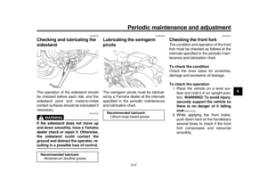
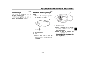
Instrument and control functions
3-10
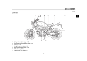
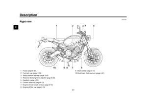
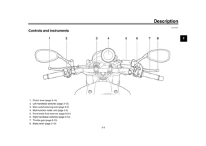
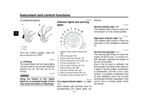
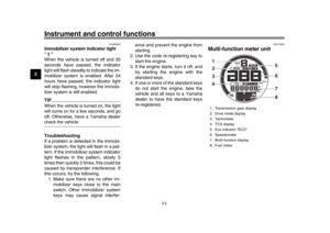
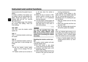
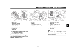
1
234
5
6
7
8
9
10
11
12
amount of fuel necessary to travel
100 km.
“AVE_ _._ MPG”: The average
distance that can be traveled on
1.0 Imp.gal of fuel.
To switch the average fuel consump-
tion display settings, push the bottom
set button until the display changes.
To reset the average fuel consumption,
select it by pushing the bottom set but-
ton. The average fuel consumption dis-
play will flash for a few seconds. While
the display is flashing, push the top set
button until the display is reset.
TIPAfter resetting the average fuel con-
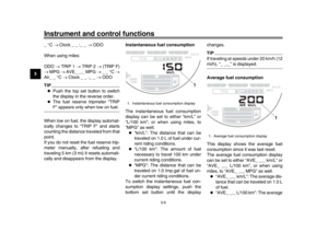
sumption, “_ _._” will be shown until thevehicle has traveled 1 km (0.6 mi). Coolant temperature
This display shows the coolant temper-
ature from 40
C to 116 C in 1 C incre-
ments.
If the message “HI” flashes, stop the
vehicle, then stop the engine and let it
cool. (See page 6-39.)
TIP
When the coolant temperature is
below 40 C, “Lo” will be displayed.
The coolant temperature varies
with changes in the weather andengine load. Air temperature
This display shows the air temperature
from –9
C to 99 C in 1 C increments.
The temperature displayed may vary
from the actual ambient temperature.
TIP
When the air temperature is below
–9 C, “Lo” will be displayed.
The accuracy of the temperature
reading may be affected when rid-
ing slowly (under 20 km/h [12 mi/h])
or when stopped at traffic signals,railroad crossings, etc.
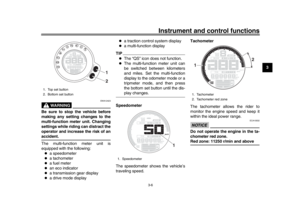
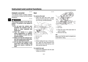
1. Coolant temperature display
1
1. Air temperature display
1
BAE-28199-E1.book 10 ページ 2019年8月23日 金曜日 午後3時56分
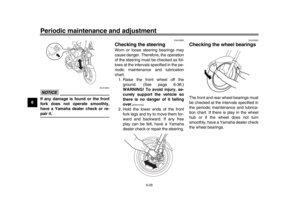
Page 26 of 102

Instrument and control functions
3-11
1
23
4
5
6
7
8
9
10
11
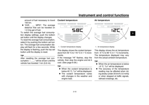
12 Clock
The clock uses a 12-hour time system.
When the vehicle is turned off, the clock
can be viewed by pushing the bottom
set button.
To set the clock
1. Turn the main switch on.
2. Switch the display to the clock.
3. Push the bottom set button and top
set button together for two sec-
onds and the hour digits will start
flashing.
4. Push the top set button to set the hours.
5. Push the bottom set button and the minute digits will start flashing. 6. Push the top set button to set the
minutes.
7. Push the bottom set button to con- firm settings and start the clock.
TIPWhen setting the hours and minutes,
push the top set button briefly to in-
crease the increment value one by one,
or push and hold the button to increasethe increment value continuously.
Display brightness
The brightness level of the multi-func-
tion meter unit panel can be adjusted to
six brightness level settings. To adjust the brightness
1. Turn the main switch off.
2. Push and hold the bottom set but-
ton.
3. Turn the main switch on and con- tinue pushing the bottom set but-
ton until the display switches to the
brightness level display.
4. Push the top set button to set the brightness level.
5. Push the bottom set button to con- firm the selected brightness level
and exit the brightness level dis-
play.
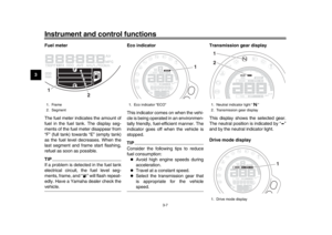
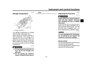
1. Clock
1
1. Brightness level display
1
BAE-28199-E1.book 11 ページ 2019年8月23日 金曜日 午後3時56分
Page 27 of 102
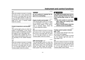
D-mode is an electronically controlled
engine performance system with three
mode selections: “STD”, “A�")
Instrument and control functions
3-12
1
234
5
6
7
8
9
10
11
12
EAU47636
D-mode (drive mode)D-mode is an electronically controlled
engine performance system with three
mode selections: “STD”, “A”, and “B”.
Push the drive mode switch “MODE” to
switch between modes. (See
page 3-14.)TIPBefore using D-mode, make sure you
understand its operation along with theoperation of the drive mode switch.
Mode “STD”
Mode “STD” is suitable for various rid-
ing conditions.
This mode allows the rider to enjoy smooth and sporty drivability from the
low-speed range to the high-speed
range.
Mode “A”
Mode “A” offers a sportier engine re-
sponse in the low- to mid-speed range
compared to mode “STD”.
Mode “B”
Mode “B” offers response that is some-
what less sharp compared to mode
“STD” for riding situations that require
especially sensitive throttle operation.
EAU1234M
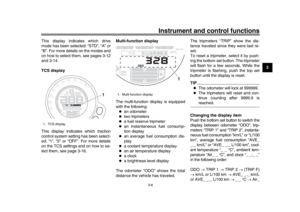
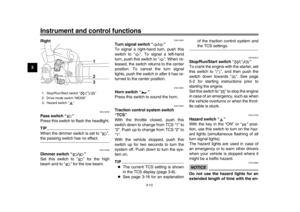
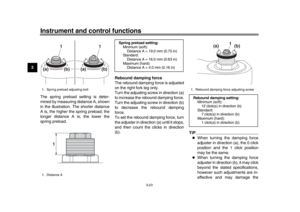
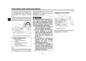
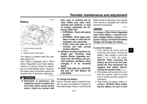
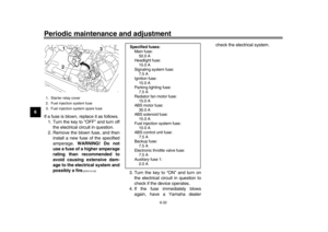
Handlebar switchesLeft
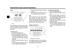
1. Drive mode switch “MODE”
1
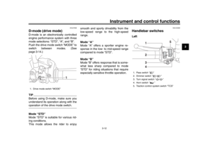
1. Pass switch “ ”
2. Dimmer switch “ / ”
3. Turn signal switch “ / ”
4. Horn switch “ ”
5. Traction control system switch “TCS”
2341
5
BAE-28199-E1.book 12 ページ 2019年8月23日 金曜日 午後3時56分
Page 28 of 102

Instrument and control functions
3-13
1
23
4
5
6
7
8
9
10
11
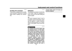
12 Right
EAU12352
Pass switch “ ”
Press this switch to flash the headlight.TIPWhen the dimmer switch is set to “ ”,the passing switch has no effect.
EAU12402
Dimmer switch “ / ”
Set this switch to “ ” for the high
beam and to “ ” for the low beam.
EAU12461
Turn signal switch “ / ”
To signal a right-hand turn, push this
switch to “ ”. To signal a left-hand
turn, push this switch to “ ”. When re-
leased, the switch returns to the center
position. To cancel the turn signal
lights, push the switch in after it has re-
turned to the center position.
EAU12501
Horn switch “ ”
Press this switch to sound the horn.
EAU73391
Traction control system switch
“TCS”
With the throttle closed, push this
switch down to change from TCS “1” to
“2”. Push up to change from TCS “2” to
“1”.
With the vehicle stopped, push this
switch up for two seconds to turn the
system off. Push down to turn the sys-
tem on.TIP
The current TCS setting is shown
in the TCS display (page 3-8).
See page 3-16 for an explanation of the traction control system and
the TCS settings.
EAU54212
Stop/Run/Start switch “ / / ”
To crank the engine with the starter, set
this switch to “ ”, and then push the
switch down towards “ ”. See page
5-2 for starting instructions prior to
starting the engine.
Set this switch to “ ” to stop the engine
in case of an emergency, such as when
the vehicle overturns or when the throt-
tle cable is stuck.
EAU12735
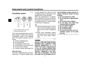
Hazard switch “ ”
With the key in the “ON” or “ ” posi-
tion, use this switch to turn on the haz-
ard lights (simultaneous
flashing of all
turn signal lights).
The hazard lights are used in case of
an emergency or to warn other drivers
when your vehicle is stopped where it
might be a traffic hazard.NOTICE
ECA10062
Do not use the hazard lights for an
extended length of time with the en-
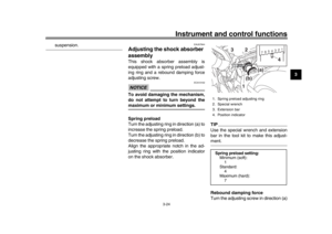
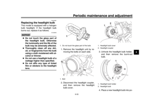
1. Stop/Run/Start switch “ / / ”
2. Drive mode switch “MODE”
3. Hazard switch “ ”
123
BAE-28199-E1.book 13 ページ 2019年8月23日 金曜日 午後3時56分
Page 29 of 102

Instrument and control functions
3-14
1
234
5
6
7
8
9
10
11
12
gine not running, otherwise the bat-
tery may discharge.
EAU73321
Drive mode switch “MODE”
WARNING
EWA18440
Do not change the drive mode whilethe vehicle is moving.
With the throttle grip closed, press this
switch to change the drive mode (page
3-12) in the following order:
A
B STD ATIP
The current drive mode is shown in
the drive mode display (page 3-7).
The current drive mode is savedwhen the vehicle is turned off.
EAU12823
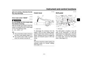
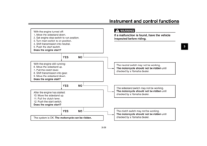
Clutch leverTo disengage the drivetrain from the
engine, such as when shifting gears,
pull the clutch lever toward to the han-
dlebar. Release the lever to engage the
clutch and transmit power to the rear
wheel.TIPThe lever should be pulled rapidly and
released slowly for smooth shifting.(See page 5-3.)
EAU12876
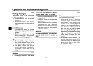
Shift pedalThe shift pedal is located on the left
side of the motorcycle. To shift the
transmission to a higher gear, move the
shift pedal up. To shift the transmission
to a lower gear, move the shift pedal
down. (See page 5-3.)
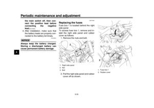
1. Clutch lever
1
1. Shift pedal
1
BAE-28199-E1.book 14 ページ 2019年8月23日 金曜日 午後3時56分
Page 30 of 102

Instrument and control functions
3-15
1
23
4
5
6
7
8
9
10
11
12
EAU26827
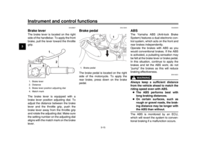
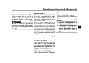
Brake leverThe brake lever is located on the right
side of the handlebar. To apply the front
brake, pull the lever toward the throttle
grip.
The brake lever is equipped with a
brake lever position adjusting dial. To
adjust the distance between the brake
lever and the throttle grip, push the
brake lever away from the throttle grip
and rotate the adjusting dial. Make sure
the setting number on the adjusting dial
aligns with the match mark on the brake
lever.
EAU12944
Brake pedalThe brake pedal is located on the right
side of the motorcycle. To apply the
rear brake, press down on the brake
pedal.
EAU63040
ABSThe Yamaha ABS (Anti-lock Brake
System) features a dual electronic con-
trol system, which acts on the front and
rear brakes independently.
Operate the brakes with ABS as you
would conventional brakes. If the ABS
is activated, a pulsating sensation may
be felt at the brake lever or brake pedal.
In this situation, continue to apply the
brakes and let the ABS work; do not
“pump” the brakes as this will reduce
braking effectiveness.
WARNING
EWA16051
Always keep a sufficient distance
from the vehicle ahead to match the
riding speed even with ABS.
The ABS performs best with
long braking distances.
On certain surfaces, such as
rough or gravel roads, the brak-
ing distance may be longer withthe ABS than without.
The ABS is monitored by an ECU,
which will revert the system to conven-
tional braking if a malfunction occurs.
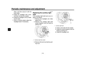
1. Brake lever
2. Distance
3. Brake lever position adjusting dial
4. Match mark
1
2
4
3
1. Brake pedal
1
BAE-28199-E1.book 15 ページ 2019年8月23日 金曜日 午後3時56分
Page 31 of 102

Instrument and control functions
3-16
1
234
5
6
7
8
9
10
11
12
TIP
The ABS performs a self-diagno-
sis test each time the vehicle first
starts off after the key is turned to
“ON” and the vehicle has traveled
at a speed of 10 km/h (6 mi/h) or
higher. During this test, a “clicking”
noise can be heard from the hy-
draulic control unit, and if the brake
lever or brake pedal is even slight-
ly applied, a vibration can be felt at
the lever and pedal, but these do
not indicate a malfunction.
This ABS has a test mode which
allows the owner to experience the
pulsation at the brake lever or
brake pedal when the ABS is oper-
ating. However, special tools are
required, so please consult yourYamaha dealer.
NOTICE
ECA20100
Be careful not to damage the wheel
sensor or wheel sensor rotor; other-
wise, improper performance of theABS will result.
EAU74351
Traction control systemThe traction control system (TCS)
helps maintain traction when accelerat-
ing on slippery surfaces, such as un-
paved or wet roads. If sensors detect
that the rear wheel is starting to slip (un-
controlled spinning), the traction control
system assists by regulating engine
power as needed until traction is re-
stored.
WARNING
EWA15433
The traction control system is not a
substitute for riding appropriately
for the conditions. Traction control
cannot prevent loss of traction due
to excessive speed when entering
turns, when accelerating hard at a
sharp lean angle, or while braking,
and cannot prevent front wheel slip-
ping. As with any vehicle, approach
surfaces that may be slippery with
caution and avoid especially slip-pery surfaces.
The “ ” indicator light flashes when
traction control has engaged. You may
notice slight changes in engine and ex-
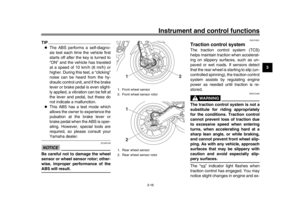
1. Front wheel sensor
2. Front wheel sensor rotor
1. Rear wheel sensor
2. Rear wheel sensor rotor
1
2
12
BAE-28199-E1.book 16 ページ 2019年8月23日 金曜日 午後3時56分
Page 32 of 102

Instrument and control functions
3-17
1
23
4
5
6
7
8
9
10
11
12 haust sounds when the system has en-
gaged.
In certain conditions, the traction con-
trol system may be automatically dis-
abled. Should this happen, the “ ”
indicator light and the “ ” warning
light will come on.
The TCS display (page 3-8) indicates
the current TCS setting. There are
three settings.
TCS “OFF”
TCS “OFF” turns the traction control
system off.
TCS “1”
TCS “1” minimizes traction control sys-
tem assist.
TCS “2”
TCS “2” maximizes traction control as-
sist; wheel spin is most strongly con-
trolled.
TIP
Use the traction control switch
(page 3-13) to change TCS set-
tings.
Traction control can be turned on or off only when the vehicle is
stopped.
When the key is turned to “ON”,
traction control is turned on and
set to TCS “1” or “2” (whichever
was last selected).
Turn the traction control system off
to help free the rear wheel if the ve-
hicle gets stuck in mud, sand, orother soft surfaces.
NOTICE
ECA16801
Use only the specified tires. (See
page 6-16.) Using different sized
tires will prevent the traction control
system from controlling tire rotationaccurately.
Resetting the traction control sys-
tem
The traction control system will auto-
matically disable when:
the front wheel or rear wheel
comes off the ground while riding.
excessive rear wheel spin is de-
tected while riding.
either wheel is rotated with the key
turned to “ON” (such as when per- forming maintenance).
If the traction control system is dis-
abled, both the “ ” indicator light and
the “ ” warning light will come on.
Should this occur, try resetting the sys-
tem as follows. 1. Stop the vehicle and turn the key to “OFF”.
2. Wait a few seconds and then turn key back “ON”.
3. The “ ” indicator light should turn off and the system be enabled.
TIPIf the “ ” indicator light remains on af-
ter resetting, the vehicle may still be rid-
den; however, have a Yamaha dealercheck the vehicle as soon as possible.
4. Have a Yamaha dealer check the vehicle and turn off the “ ” warn-
ing light.
BAE-28199-E1.book 17 ページ 2019年8月23日 金曜日 午後3時56分