2020 YAMAHA TRICITY 300 AUX
[x] Cancel search: AUXPage 8 of 114

Table of contentsSafety information ............................ 1-1
Further safe-riding points ............... 1-5
Description ....................................... 2-1
Left view ......................................... 2-1
Right view ....................................... 2-2
Controls and instruments ............... 2-3
Smart key system ........................... 3-1
Smart key system ........................... 3-1
Operating range of the smart key system......................................... 3-2
Handling of the smart key and mechanical keys ......................... 3-3
Smart key ....................................... 3-4
Replacing the smart key battery..... 3-6
Main switch .................................... 3-7
Stan din g assist ................................. 4-1
Standing assist ............................... 4-1
Instrument an d control functions ... 5-1
Indicator lights and warning
lights............................................ 5-1
Multi-function meter unit ................ 5-3
Handlebar switches ........................ 5-8
Front brake lever .......................... 5-10
Brake pedal .................................. 5-10
Rear brake lever ........................... 5-11
Parking brake lever ....................... 5-12
ABS .............................................. 5-12 Traction control system ................ 5-13
Fuel tank cap ................................ 5-15
Fuel ............................................... 5-16
Fuel tank overflow hose ................ 5-18
Catalytic converter ........................ 5-18
Storage compartment ................... 5-18
Adjusting the shock absorber
assemblies ................................. 5-20
Auxiliary DC jack ........................... 5-20
Sidestand ...................................... 5-21
Ignition circuit cut-off system ....... 5-22
For your safety – pre-operation
checks ............................................... 6-1
Operation an d important ri din g
points ................................................. 7-1
Engine break-in ............................... 7-1
Starting the engine .......................... 7-2
Starting off ...................................... 7-3
Acceleration and deceleration ........ 7-3
Braking ............................................ 7-3
Tips for reducing fuel consumption ................................ 7-4
Parking ............................................ 7-4
Perio dic maintenance an d
a d justment ........................................ 8-1
Tool kit ............................................ 8-2
Periodic maintenance charts .......... 8-3 Periodic maintenance chart for the
emission control system ............. 8-3
General maintenance and lubrication chart .......................... 8-4
Removing and installing the
panel............................................ 8-9
Checking the spark plug............... 8-10
Canister ........................................ 8-11
Engine oil and oil filter element..... 8-12
Why Yamalube.............................. 8-14
Final transmission oil .................... 8-14
Coolant ......................................... 8-15
Air filter and V-belt case air filter elements .................................... 8-17
Checking the throttle grip free play ............................................ 8-21
Valve clearance............................. 8-21
Tires .............................................. 8-22
Cast wheels .................................. 8-23
Checking the front brake lever
free play..................................... 8-24
Checking the rear brake lever free play..................................... 8-24
Checking the parking brake ......... 8-25
Checking the front and rear brake pads ................................ 8-25
Checking the brake fluid level ...... 8-26
Changing the brake fluid .............. 8-27
Checking the V-belt ...................... 8-27
Checking and lubricating the cables ........................................ 8-28UBX9E0E0.book Page 1 Monday, January 20, 2020 10:54 AM
Page 18 of 114
Description
2-3
2
EAU10431
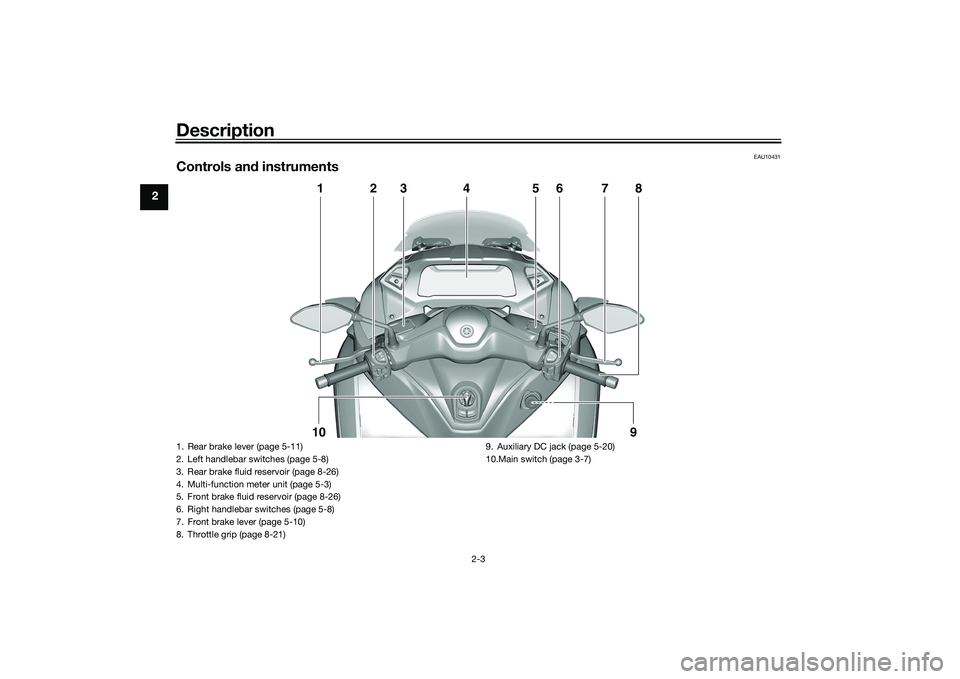
Controls and instruments
1
2
3
4
5
6
7
8
10
9
1. Rear brake lever (page 5-11)
2. Left handlebar switches (page 5-8)
3. Rear brake fluid reservoir (page 8-26)
4. Multi-function meter unit (page 5-3)
5. Front brake fluid reservoir (page 8-26)
6. Right handlebar switches (page 5-8)
7. Front brake lever (page 5-10)
8. Throttle grip (page 8-21) 9. Auxiliary DC jack (page 5-20)
10.Main switch (page 3-7)UBX9E0E0.book Page 3 Monday, January 20, 2020 10:54 AM
Page 51 of 114
Instrument and control functions
5-20
5
EAU14895
A djustin g the shock a bsor ber
assem blies
WARNING
EWA10211
Always a djust both shock a bsor ber
assem blies equally, otherwise poor
han dlin g an d loss of sta bility may re-
sult.Each shock absorber assembly is
equipped with a spring preload adjust-
ing ring.NOTICE
ECA10102
To avoi d d amag ing the mechanism,
d o not attempt to turn b eyond the
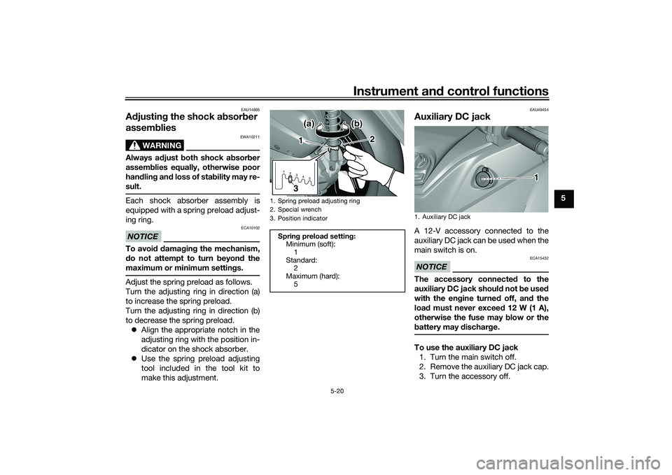
maximum or minimum settin gs.Adjust the spring preload as follows.
Turn the adjusting ring in direction (a)
to increase the spring preload.
Turn the adjusting ring in direction (b)
to decrease the spring preload.
Align the appropriate notch in the
adjusting ring with the position in-
dicator on the shock absorber.
Use the spring preload adjusting
tool included in the tool kit to
make this adjustment.
EAU49454
Auxiliary DC jackA 12-V accessory connected to the
auxiliary DC jack can be used when the
main switch is on.NOTICE
ECA15432
The accessory connecte d to the
auxiliary DC jack shoul d not b e used
with the en gine turne d off, an d the
loa d must never excee d 12 W (1 A),
otherwise the fuse may blow or the
b attery may dischar ge.To use the auxiliary DC jack
1. Turn the main switch off.
2. Remove the auxiliary DC jack cap.
3. Turn the accessory off.
1. Spring preload adjusting ring
2. Special wrench
3. Position indicator
Sprin g preloa d settin g:
Minimum (soft):
1
Standard: 2
Maximum (hard): 51 2345
1
2
3(a)
(a) (b) (b)
(a) (b)
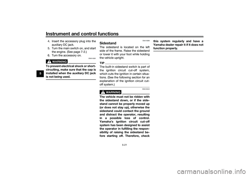
1. Auxiliary DC jack
1
UBX9E0E0.book Page 20 Monday, January 20, 2020 10:54 AM
Page 52 of 114
Instrument and control functions
5-21
5 4. Insert the accessory plug into the
auxiliary DC jack.
5. Turn the main switch on, and start the engine. (See page 7-2.)
6. Turn the accessory on.
WARNING
EWA14361
To prevent electrical shock or short-
circuiting , make sure that the cap is
installe d when the auxiliary DC jack
is not bein g use d.
EAU15306
Si destan dThe sidestand is located on the left
side of the frame. Raise the sidestand
or lower it with your foot while holding
the vehicle upright.TIPThe built-in sidestand switch is part of
the ignition circuit cut-off system,
which cuts the ignition in certain situa-
tions. (See the following section for an
explanation of the ignition circuit cut-
off system.)
WARNING
EWA10242
The vehicle must not be ri dden with
the si destan d d own, or if the si de-
stan d cannot b e properly moved up
(or does not stay up), otherwise the
si destan d coul d contact the groun d
an d d istract the operator, resultin g
in a possi ble loss of control.
Yamaha’s ig nition circuit cut-off
system has been desi gne d to assist
the operator in fulfillin g the respon-
si bility of raisin g the si destan d b e-
fore startin g off. Therefore, check this system reg
ularly and have a
Yamaha dealer repair it if it does not
function properly.
UBX9E0E0.book Page 21 Monday, January 20, 2020 10:54 AM
Page 93 of 114
![YAMAHA TRICITY 300 2020 Owners Manual Periodic maintenance an d a djustment
8-33
8
connect the positive lea
d b efore
connectin g the ne gative lea d.
[ECA16842]
4. After installation, make sure that
the battery leads are properly con-
ne YAMAHA TRICITY 300 2020 Owners Manual Periodic maintenance an d a djustment
8-33
8
connect the positive lea
d b efore
connectin g the ne gative lea d.
[ECA16842]
4. After installation, make sure that
the battery leads are properly con-
ne](/manual-img/51/51928/w960_51928-92.png)
Periodic maintenance an d a djustment
8-33
8
connect the positive lea
d b efore
connectin g the ne gative lea d.
[ECA16842]
4. After installation, make sure that
the battery leads are properly con-
nected to the battery terminals.NOTICE
ECA16531
Always keep the b attery charged .
Storin g a dischar ged battery can
cause permanent battery damag e.
EAU89081
Replacin g the fusesThe main fuse and the fuse boxes,
which contain the fuses for the individ-
ual circuits, are located behind panel A.
(See page 8-9.)TIPTo access the main fuse, remove the
starter relay cover as shown.1. Starter relay cover
2. Spare main fuse
3. Main fuse
2 2
3 2
3
1
1. Backup fuse
2. Radiator fan motor fuse
3. Ignition fuse
4. ABS control unit fuse
5. Signaling system fuse
6. Grip warmer fuse
7. Spare fuse
8. Headlight fuse
9. ABS motor fuse
10.ABS solenoid fuse
11.Hazard fuse
12.Auxiliary DC jack fuse
13.Answer back fuse
14.Standing assist battery fuse
15.Standing assist fuse
14157
910111213
7
123465
7
8
UBX9E0E0.book Page 33 Monday, January 20, 2020 10:54 AM
Page 94 of 114

Periodic maintenance an d a djustment
8-34
8 If a fuse is blown, replace it as follows.
1. Turn the main switch off and turn off the electrical circuit in ques-
tion.
2. Remove the blown fuse, and then install a new fuse of the specified
amperage. WARNING! Do not
use a fuse of a hi gher ampera ge
ratin g than recommen ded to
avoi d causin g extensive d am-
a g e to the electrical system an d
possi bly a fire.
[EWA15132]
3. Turn the main switch on and turn
on the electrical circuit in question
to check if the device operates.
4. If the fuse immediately blows again, have a Yamaha dealer
check the electrical system.
Specifie d fuses:
Main fuse:
20.0 A
Grip warmer fuse:
7.5 A
Headlight fuse: 7.5 A
Signaling system fuse: 10.0 A
Ignition fuse:
7.5 A
Radiator fan motor fuse: 7.5 A
Backup fuse: 7.5 A
Hazard fuse:
7.5 A
ABS control unit fuse: 7.5 A
ABS motor fuse: 30.0 A
ABS solenoid fuse:
20.0 A
Answer back fuse: 2.0 A
Auxiliary DC jack fuse: 2.0 A
Standing assist fuse:
7.5 A
Standing assist battery fuse: 20.0 A
UBX9E0E0.book Page 34 Monday, January 20, 2020 10:54 AM
Page 95 of 114
Periodic maintenance an d a djustment
8-35
8
EAUN2261
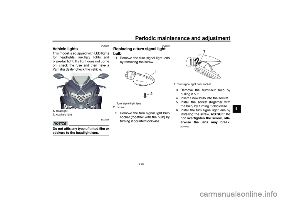
Vehicle li ghtsThis model is equipped with LED lights
for headlights, auxiliary lights and
brake/tail light. If a light does not come
on, check the fuse and then have a
Yamaha dealer check the vehicle.NOTICE
ECA16581
Do not affix any type of tinte d film or
stickers to the head lig ht lens.
EAU62590
Replacin g a turn sig nal light
b ul b1. Remove the turn signal light lens
by removing the screw.
2. Remove the turn signal light bulb socket (together with the bulb) by
turning it counterclockwise. 3. Remove the burnt-out bulb by
pulling it out.
4. Insert a new bulb into the socket.
5. Install the socket (together with the bulb) by turning it clockwise.
6. Install the turn signal light lens by installing the screw. NOTICE: Do
not overti ghten the screw, oth-
erwise the lens may break.
[ECA11192]
1. Headlight
2. Auxiliary light
1 1
1
2
2
1. Turn signal light lens
2. Screw
2
1
1. Turn signal light bulb socket
1
UBX9E0E0.book Page 35 Monday, January 20, 2020 10:54 AM
Page 107 of 114
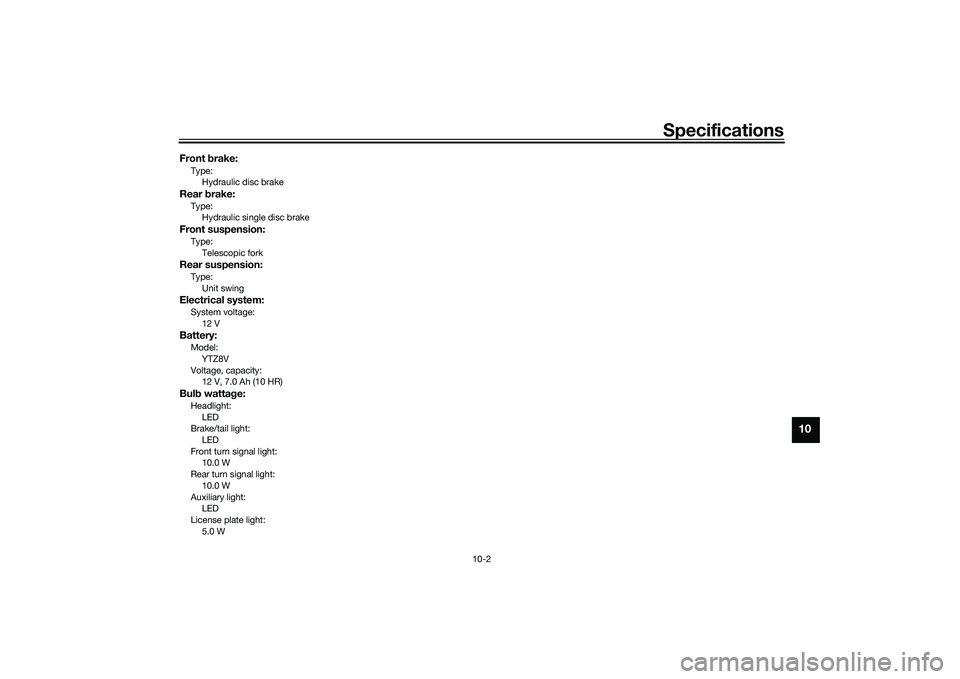
Specifications
10-2
10
Front brake:Type:
Hydraulic disc brakeRear brake:Type:
Hydraulic single disc brakeFront suspension:Type:
Telescopic forkRear suspension:Type:Unit swingElectrical system:System voltage:12 VBattery:Model:
YTZ8V
Voltage, capacity: 12 V, 7.0 Ah (10 HR)Bul b watta ge:Headlight:
LED
Brake/tail light: LED
Front turn signal light: 10.0 W
Rear turn signal light:
10.0 W
Auxiliary light: LED
License plate light: 5.0 W
UBX9E0E0.book Page 2 Monday, January 20, 2020 10:54 AM