2020 YAMAHA TRICITY 300 ECO mode
[x] Cancel search: ECO modePage 9 of 114
Table of contents
Checking and lubricating the
throttle grip and cable ................8-28
Lubricating the front and rear brake levers................................8-28
Checking and lubricating the
brake pedal ................................8-29
Checking and lubricating the centerstand and sidestand ........8-29
Checking the front fork..................8-30
Checking the steering ...................8-31
Lubricating the steering bearings .....................................8-31
Checking the wheel bearings ........8-31
Battery ...........................................8-32
Replacing the fuses .......................8-33
Vehicle lights .................................8-35
Replacing a turn signal light bulb ............................................8-35
Replacing the license plate light bulb ............................................8-36
Troubleshooting ............................8-36
Troubleshooting chart ...................8-38
Emergency mode .........................8-40
Vehicle care an d stora ge .................9-1
Matte color caution .........................9-1
Care .................................................9-1
Storage ............................................9-3 Specifications
................................. 10-1
Consumer information ................... 11-1
Identification numbers .................. 11-1
Diagnostic connector.................... 11-2
Vehicle data recording .................. 11-2
In dex ................................................ 12-1
UBX9E0E0.book Page 2 Monday, January 20, 2020 10:54 AM
Page 26 of 114

Smart key system
3-8
3main switch knob and confirmation
with the smart key has taken place, the
main switch can be turned while the
smart key system indicator light is on
(approximately 4 seconds).
WARNING
EWA18720
Never turn the main switch to
“OFF”, “ ”, or “OPEN” while the ve-
hicle is movin
g. Otherwise the elec-
trical systems will be switche d off,
which may result in loss of control or
an acci dent.TIPDo not push the main switch knob re-
peatedly or turn the main switch back
and forth beyond normal use. Other-
wise, to protect the main switch from
damage, the smart key system will
temporarily disable and the smart key
system indicator light will flash. If this
occurs, wait until the indicator light
stops flashing before operating the
main switch again.The main switch positions are de-
scribed below.
EAU76500
ON (on)
All electrical circuits are supplied with
the power, and the engine can be start-
ed.
To turn the vehicle power on1. Turn the smart key on and bring it
within operating range.
2. Push the main switch knob and the smart key indicator light will
come on for approximately 4 sec-
onds. 3. While the smart key system indi-
cator light is on, turn the main
switch to “ON”. All of the turn sig-
nal lights flash twice and the vehi-
cle power turns on.
TIPIf the vehicle battery voltage is
low, the turn signal lights will not
flash.
See “Emergency mode” on page
8-40 for information on turning the
vehicle power on without the
smart key.
EAU76510
OFF (off)
All electrical systems are off.
1. Push.
2. Turn.1
2
1. Turn.
1
UBX9E0E0.book Page 8 Monday, January 20, 2020 10:54 AM
Page 58 of 114

Operation and important rid ing points
7-2
7
EAU86720
Startin g the eng ineThe ignition circuit cut-off system will
enable starting when the sidestand is
be up.
To start the engine1. Turn the main switch on and set
the engine stop switch to the run
position.
2. Confirm the indicator and warning light(s) come on for a few sec-
onds, and the go off. (See page
5-1.)TIPDo not start the engine if the en-
gine trouble warning light remains
on.
The ABS warning light should
come on and stay on until the ve-
hicle reaches a speed of 10 km/h
(6 mi/h).NOTICE
ECA24110
If a warnin g or in dicator li ght does
not work as d escribed a bove, have a
Yamaha dealer check the vehicle.3. Close the throttle completely. 4. While applying the front or rear
brake, push the start switch.
5. Release the start switch when the engine starts, or after 5 seconds.
Wait 10 seconds before pressing
the switch again to allow battery
voltage to restore.
NOTICE
ECA11043
For maximum en gine life, never ac-
celerate har d when the en gine is
col d!
EAU78221
TIPThis model is equipped with a lean an-
gle sensor to stop the engine in case of
a turnover. In this case, the engine
trouble warning light will come on but
this is not a malfunction. Before re-
starting the engine, turn the main
switch off and then back on to reset the
engine trouble warning light. Failing to
do so will prevent the engine from
starting even though the engine will
crank when pushing the start switch.
UBX9E0E0.book Page 2 Monday, January 20, 2020 10:54 AM
Page 100 of 114
Periodic maintenance an d a djustment
8-40
8
EAU76561
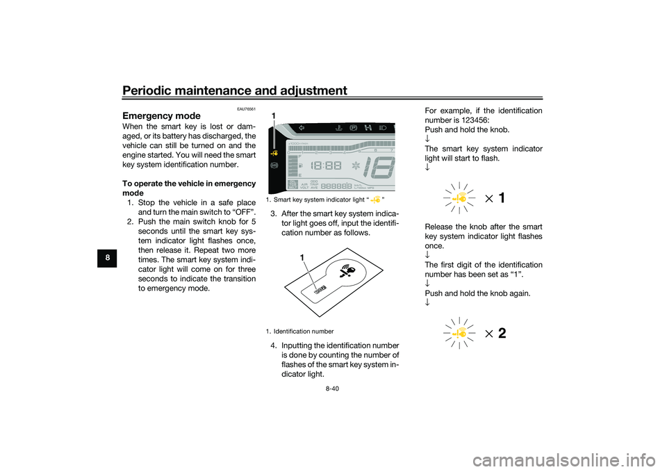
Emer gency mo de When the smart key is lost or dam-
aged, or its battery has discharged, the
vehicle can still be turned on and the
engine started. You will need the smart
key system identification number.
To operate the vehicle in emer gency
mo de
1. Stop the vehicle in a safe place and turn the main switch to “OFF”.
2. Push the main switch knob for 5 seconds until the smart key sys-
tem indicator light flashes once,
then release it. Repeat two more
times. The smart key system indi-
cator light will come on for three
seconds to indicate the transition
to emergency mode. 3. After the smart key system indica-
tor light goes off, input the identifi-
cation number as follows.
4. Inputting the identification number is done by counting the number of
flashes of the smart key system in-
dicator light. For example, if the identification
number is 123456:
Push and hold the knob.
↓
The smart key system indicator
light will start to flash.
↓
Release the knob after the smart
key system indicator light flashes
once.
↓
The first digit of the identification
number has been set as “1”.
↓
Push and hold the knob again.
↓
1. Smart key system indicator light “ ”
1. Identification number1
123456
1
UBX9E0E0.book Page 40 Monday, January 20, 2020 10:54 AM
Page 101 of 114

Periodic maintenance an d a djustment
8-41
8
Release the knob after the smart
key system indicator light flashes
twice.
↓
The second digit has been set as
“2”.
↓
Repeat the above procedure until
all digits of the identification num-
ber have been set. The smart key
system indicator light will flash for
10 seconds if the correct identifi-
cation number was entered.
TIPWhen one of the following situations
applies, emergency mode will be ter-
minated and the smart key system in-
dicator light will flash quickly for 3
seconds. In this case, start over again
from step 2.
When there are no knob opera-
tions for 10 seconds during the
identification number input pro-
cess.
When the smart key system indi-
cator light is allowed to flash nine
or more times.
The identification number is not
entered correctly.
5. While the smart key system indi-
cator light is on, push the knob
once more to complete emergen-
cy mode access. The smart key
indicator light will go off and then
come back on for approximately 4
seconds.
6. While the smart key system indi- cator light is on, turn the main
switch to “ON”. The vehicle can
now be operated normally.
UBX9E0E0.book Page 41 Monday, January 20, 2020 10:54 AM
Page 106 of 114
Specifications
10-1
10
Dimensions:Overall length:2250 mm (88.6 in)
Overall width:
815 mm (32.1 in)
Overall height: 1470 mm (57.9 in)
Seat height: 795 mm (31.3 in)
Wheelbase:
1595 mm (62.8 in)
Ground clearance: 130 mm (5.12 in)
Minimum turning radius: 3.2 m (10.50 ft)Wei ght:Curb weight:
239 kg (527 lb)Engine:Combustion cycle:
4-stroke
Cooling system: Liquid cooled
Valve train: SOHC
Number of cylinders:
Single cylinder
Displacement: 292 cm³
Bore × stroke:
70.0 × 75.9 mm (2.76 × 2.99 in)
Starting system:
Electric starter
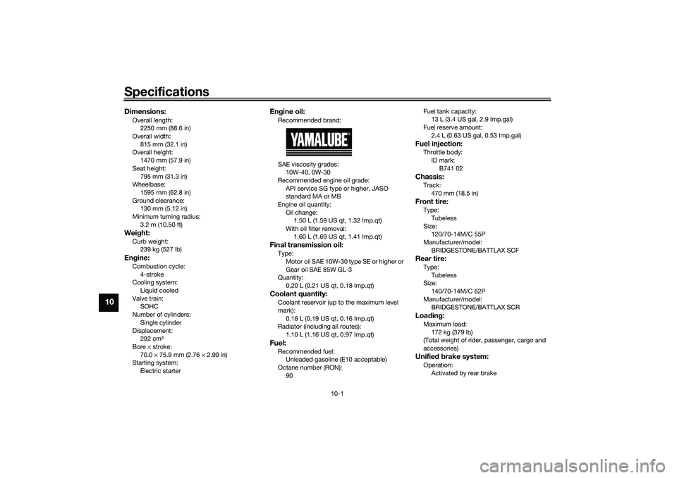
Engine oil:Recommended brand:
SAE viscosity grades:
10W-40, 0W-30
Recommended engine oil grade: API service SG type or higher, JASO
standard MA or MB
Engine oil quantity: Oil change: 1.50 L (1.59 US qt, 1.32 Imp.qt)
With oil filter removal: 1.60 L (1.69 US qt, 1.41 Imp.qt)Final transmission oil:Type:Motor oil SAE 10W-30 type SE or higher or
Gear oil SAE 85W GL-3
Quantity: 0.20 L (0.21 US qt, 0.18 Imp.qt)Coolant quantity:Coolant reservoir (up to the maximum level
mark):0.18 L (0.19 US qt, 0.16 Imp.qt)
Radiator (including all routes):
1.10 L (1.16 US qt, 0.97 Imp.qt)Fuel:Recommended fuel:Unleaded gasoline (E10 acceptable)
Octane number (RON):
90 Fuel tank capacity:
13 L (3.4 US gal, 2.9 Imp.gal)
Fuel reserve amount: 2.4 L (0.63 US gal, 0.53 Imp.gal)
Fuel injection:Throttle body:ID mark:
B741 02Chassis:Track:470 mm (18.5 in)Front tire:Type:Tubeless
Size: 120/70-14M/C 55P
Manufacturer/model:
BRIDGESTONE/BATTLAX SCFRear tire:Type:Tubeless
Size:
140/70-14M/C 62P
Manufacturer/model: BRIDGESTONE/BATTLAX SCRLoa din g:Maximum load:
172 kg (379 lb)
(Total weight of rider, passenger, cargo and
accessories)Unifie d b rake system:Operation:
Activated by rear brake
UBX9E0E0.book Page 1 Monday, January 20, 2020 10:54 AM
Page 108 of 114
Consumer information
11-1
11
EAU53562
Id entification num bersRecord the vehicle identification num-
ber, engine serial number, and the
model label information in the spaces
provided below. These identification
numbers are needed when registering
the vehicle with the authorities in your
area and when ordering spare parts
from a Yamaha dealer.
VEHICLE IDENTIFICATION NUMBER:
ENGINE SERIAL NUMBER:
MODEL LABEL INFORMATION:
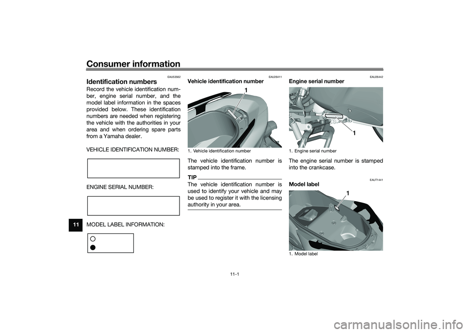
EAU26411
Vehicle i dentification num ber
The vehicle identification number is
stamped into the frame.TIPThe vehicle identification number is
used to identify your vehicle and may
be used to register it with the licensing
authority in your area.
EAU26442
En gine serial num ber
The engine serial number is stamped
into the crankcase.
EAUT1441
Mo del la bel
1. Vehicle identification number
1
1. Engine serial number
1. Model label
1
1
UBX9E0E0.book Page 1 Monday, January 20, 2020 10:54 AM
Page 109 of 114
Consumer information
11-2
11
The model label is affixed to the inside
of the storage compartment. (See
page 5-18.) Record the information on
this label in the space provided. This
information will be needed when order-
ing spare parts from a Yamaha dealer.
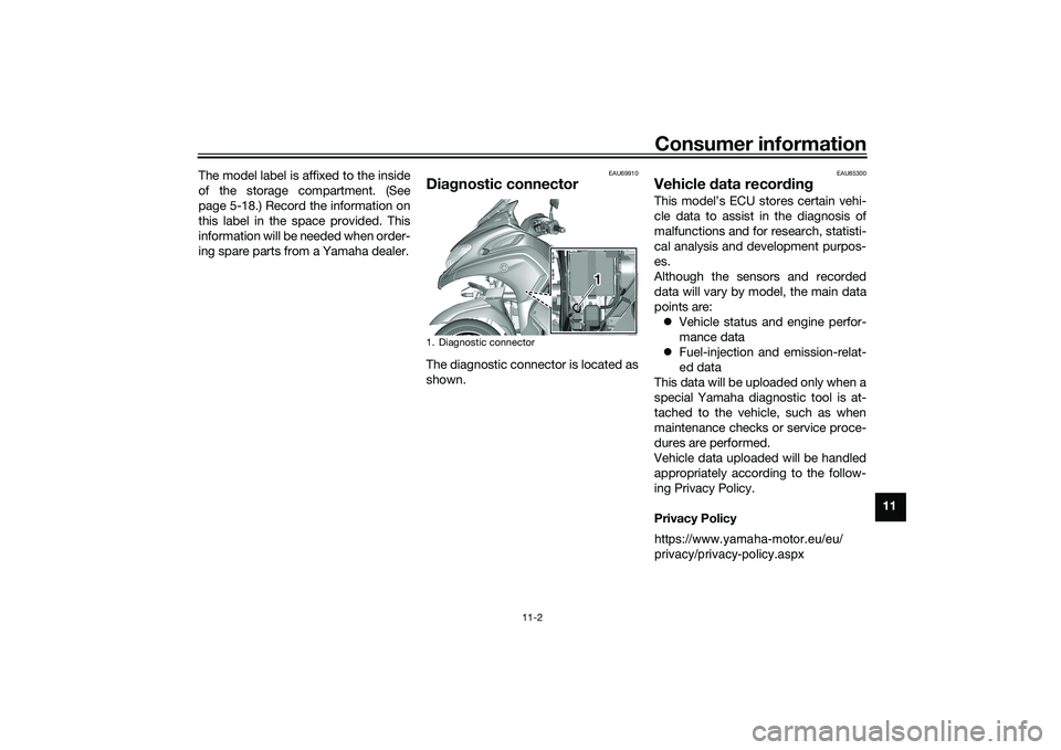
EAU69910
Dia
gnostic connectorThe diagnostic connector is located as
shown.
EAU85300
Vehicle data recor din gThis model’s ECU stores certain vehi-
cle data to assist in the diagnosis of
malfunctions and for research, statisti-
cal analysis and development purpos-
es.
Although the sensors and recorded
data will vary by model, the main data
points are:
Vehicle status and engine perfor-
mance data
Fuel-injection and emission-relat-
ed data
This data will be uploaded only when a
special Yamaha diagnostic tool is at-
tached to the vehicle, such as when
maintenance checks or service proce-
dures are performed.
Vehicle data uploaded will be handled
appropriately according to the follow-
ing Privacy Policy.
Privacy Policy
1. Diagnostic connector
1 1
https://www.yamaha-motor.eu/eu/
privacy/privacy-policy.aspx
UBX9E0E0.book Page 2 Monday, January 20, 2020 10:54 AM