Page 57 of 80
Periodic maintenance an d a djustment
7-17
7
EAU22153
A djustin g the front an d rear
b rake lever free play
The front and rear brake lever free play
should be measured at the positions as
shown.
Front
Rear
Periodically check the front and rear
brake lever free play and, if necessary,
adjust them as follows.
To increase the brake lever free play,
turn the adjusting nut at the brake shoe
plate in direction (a). To decrease the
brake lever free play, turn the adjusting
nut in direction (b). Front
Rear
WARNING
EWA10651
If proper a
djustment cannot b e ob-
taine d as d escri bed , have a Yamaha
d ealer make this a djustment.
1. Front brake lever free play
1. Rear brake lever free play
Front brake lever free play:
10.0–20.0 mm (0.39–0.79 in)
Rear brake lever free play:
10.0–20.0 mm (0.39–0.79 in)
1
1
1. Front brake lever free play adjusting nut
1. Rear brake lever free play adjusting nut
1
(a)
(b)
1
(a)(b)
U2SA86E0.book Page 17 Tuesday, April 30, 2019 11:57 AM
Page 58 of 80
Periodic maintenance an d a djustment
7-18
7
EAU41054
Checkin g the front an d rear
b rake shoes
The front and rear brake shoes must be
checked for wear at the intervals spec-
ified in the periodic maintenance and
lubrication chart.
TIP
The wheels must be removed to check
brake shoe lining thickness.
To remove the front wheel: See
page 7-23.
To remove the rear wheel: See
page 7-24.
Front
Rear
If the lining thickness of a brake shoe is
less than 1.5 mm (0.06 in), have a
Yamaha dealer replace the brake shoes as a set.
TIP
Be sure to measure the brake lining at
the thinnest portion.
U2SA86E0.book Page 18 Tuesday, April 30, 2019 11:57 AM
Page 59 of 80

Periodic maintenance an d a djustment
7-19
7
EAU23098
Checkin g an d lu bricatin g the
ca bles
The operation of all control cables and
the condition of the cables should be
checked before each ride, and the ca-
bles and cable ends should be lubri-
cated if necessary. If a cable is
damaged or does not move smoothly,
have a Yamaha dealer check or re-
place it. WARNING! Dama ge to the
outer housin g of cab les may result
in internal rustin g an d cause inter-
ference with cab le movement. Re-
place dama ged cab les as soon as
possi ble to prevent unsafe con di-
tions.
[EWA10712] EAU23115
Checkin
g an d lu bricatin g the
throttle grip an d ca ble
The operation of the throttle grip
should be checked before each ride. In
addition, the cable should be lubricat-
ed by a Yamaha dealer at the intervals
specified in the periodic maintenance
chart.
The throttle cable is equipped with a
rubber cover. Make sure that the cover
is securely installed. Even though the
cover is installed correctly, it does not
completely protect the cable from wa-
ter entry. Therefore, use care not to
pour water directly onto the cover or
cable when washing the vehicle. If the
cable or cover becomes dirty, wipe
clean with a moist cloth.
Recommen ded lu bricant:
Yamaha cable lubricant or other
suitable cable lubricant
U2SA86E0.book Page 19 Tuesday, April 30, 2019 11:57 AM
Page 60 of 80
Periodic maintenance an d a djustment
7-20
7
EAU23121
A djustin g the Autolu be pump
The Autolube pump is a vital and so-
phisticated component of the engine,
which must be adjusted by a Yamaha
dealer at the intervals specified in the
periodic maintenance and lubrication
chart.
EAU43634
Lub ricatin g the front an d rear
b rake levers
The pivoting points of the front and rear
brake levers must be lubricated at the
intervals specified in the periodic main-
tenance and lubrication chart.
Recommen ded lu bricant:
Lithium-soap-based grease
U2SA86E0.book Page 20 Tuesday, April 30, 2019 11:57 AM
Page 61 of 80

Periodic maintenance an d a djustment
7-21
7
EAU23193
Checkin g an d lu bricatin g the
centerstand
The operation of the centerstand
should be checked before each ride,
and the pivots and metal-to-metal con-
tact surfaces should be lubricated if
necessary.
WARNING
EWA11302
If the centerstan d d oes not move up
an d d own smoothly, have a Yamaha
d ealer check or repair it. Otherwise,
the centerstan d coul d contact the
g roun d an d d istract the operator, re-
sultin g in a possi ble loss of control.
EAU23273
Checkin g the front fork
The condition and operation of the
front fork must be checked as follows
at the intervals specified in the periodic
maintenance and lubrication chart.
To check the con dition
Check the inner tubes for scratches,
damage and excessive oil leakage.
To check the operation 1. Place the vehicle on a level surfa- ce and hold it in an upright posi-
tion. WARNING! To avoi d injury,
securely support the vehicle so
there is no d anger of it fallin g
over.
[EWA10752]
2. While applying the front brake, push down hard on the handle-
bars several times to check if the
front fork compresses and re-
bounds smoothly.
NOTICE
ECA10591
If any damag e is foun d or the front
fork does not operate smoothly,
have a Yamaha d ealer check or re-
pair it.
Recommen ded lu bricant:
Lithium-soap-based grease
U2SA86E0.book Page 21 Tuesday, April 30, 2019 11:57 AM
Page 62 of 80
Periodic maintenance an d a djustment
7-22
7
EAU45512
Checkin g the steerin g
Worn or loose steering bearings may
cause danger. Therefore, the operation
of the steering must be checked as fol-
lows at the intervals specified in the
periodic maintenance and lubrication
chart.
1. Place the vehicle on the center- stand. WARNING! To avoi d inju-
ry, securely support the vehicle
so there is no dan ger of it fallin g
over.
[EWA10752]
2. Hold the lower ends of the front fork legs and try to move them for-
ward and backward. If any free
play can be felt, have a Yamaha
dealer check or repair the steer-
ing.
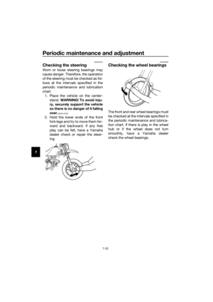
EAU23292
Checkin g the wheel b earings
The front and rear wheel bearings must
be checked at the intervals specified in
the periodic maintenance and lubrica-
tion chart. If there is play in the wheel
hub or if the wheel does not turn
smoothly, have a Yamaha dealer
check the wheel bearings.
U2SA86E0.book Page 22 Tuesday, April 30, 2019 11:57 AM
Page 63 of 80
Periodic maintenance an d a djustment
7-23
7
EAU24361
Front wheel
EAU56510
To remove the front wheel
WARNING
EWA10822
To avoi d injury, securely support the
vehicle so there is no d anger of it
fallin g over.
1. Place the motorcycle on the cen-
terstand.
2. Disconnect the brake cable at the wheel hub by removing the front
brake lever free play adjusting nut,
then removing the cable from the
brake camshaft lever and brake
shoe plate.
3. Remove the axle nut and washer.
4. Pull the wheel axle out, and then remove the wheel. To install the front wheel
1. Install the brake shoe plate into the wheel hub as shown.
2. Lift the wheel up between the fork legs.
TIP
Make sure that the slot in the brake
shoe plate fits over the retainer on the
fork leg.
1. Brake camshaft lever
2. Brake shoe plate
3. Washer
4. Axle nut
5. Brake cable
6. Front brake lever free play adjusting nut
5
6
1 3
4
2
1. Wheel axle
1. Retainer
1
1
U2SA86E0.book Page 23 Tuesday, April 30, 2019 11:57 AM
Page 64 of 80

Periodic maintenance an d a djustment
7-24
7 3. Insert the wheel axle from the right
side.
4. Install the washer and axle nut, and then tighten the axle nut to the
specified torque.
5. Connect the brake cable at the wheel hub, and then install the
brake lever free play adjusting nut.
6. Adjust the brake lever free play. (See page 7-17.)
7. Take the motorcycle off the cen- terstand so that the front wheel is
on the ground.
8. Push down hard on the handlebar several times to check for proper
fork operation.
EAU25081
Rear wheel
EAU56822
To remove the rear wheel
WARNING
EWA10822
To avoi d injury, securely support the
vehicle so there is no dan ger of it
fallin g over.
1. Place the motorcycle on the cen-
terstand.
2. Remove the seat. (See page 4-8.)
3. Remove the muffler bolt and washers. WARNING! Always let
the exhaust system cool prior to
touching exhaust components.
[EWA14582]
4. Slide the spring clamp down, and
then remove the muffler.
5. Remove the exhaust chamber bolt and washers.
Tightenin g torque:
Axle nut: 36 N·m (3.6 kgf·m, 27 lb·ft)
1. Muffler
2. Washer
3. Muffler bolt
4. Spring clamp
312 4
U2SA86E0.book Page 24 Tuesday, April 30, 2019 11:57 AM