Page 65 of 98

Periodic maintenance an d a djustment
6-17
6
Tire inspection
The tires must be checked before each
ride. If the center tread depth reaches
the specified limit, if the tire has a nail
or glass fragments in it, or if the side-
wall is cracked, have a Yamaha dealer
replace the tire immediately.
TIPThe tire tread depth limits may differ
from country to country. Always com-
ply with the local regulations.
WARNING
EWA10472
Have a Yamaha d ealer replace
excessively worn tires. Besi des
b ein g ille gal, operatin g the vehi-
cle with excessively worn tires
d ecreases ri din g sta bility an d
can lea d to loss of control.
The replacement of all wheel
and b rake-relate d parts, inclu d-
in g the tires, shoul d b e left to a
Yamaha dealer, who has the
necessary professional knowl-
e dg e an d experience to do so.
Ride at mo derate spee ds after
chan gin g a tire since the tire
surface must first be “ broken
in” for it to d evelop its optimal
characteristics.
Tire information
This model is equipped with tubeless
tires and tire air valves.
Tires age, even if they have not been
used or have only been used occasion-
ally. Cracking of the tread and sidewall
rubber, sometimes accompanied by
carcass deformation, is an evidence of
ageing. Old and aged tires shall be
checked by tire specialists to ascertain
their suitability for further use.
WARNING
EWA10902
The front an d rear tires shoul d
b e of the same make an d d e-
si gn, otherwise the han dlin g
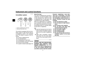
1. Tire sidewall
2. Tire tread depthMinimum tire trea d d epth (front an d
rear): 1.6 mm (0.06 in)
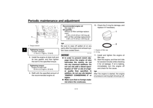
1. Tire air valve
2. Tire air valve core
3. Tire air valve cap with seal
UB4TE0E0.book Page 17 Monday, December 9, 2019 3:53 PM
Page 66 of 98

Periodic maintenance an d a djustment
6-18
6 characteristics of the motorcy-
cle may
be different, which
coul d lea d to an acci dent.
Always make sure that the valve
caps are securely installed to
prevent air pressure leakag e.
Use only the tire valves an d
valve cores listed below to
avoi d tire d eflation durin g a ri de.
After extensive tests, only the tires list-
ed below have been approved for this
model by Yamaha.
WARNING
EWA10601
This motorcycle is fitte d with super-
hi gh-spee d tires. Note the following
points in or der to make the most ef-
ficient use of these tires. Use only the specified replace-
ment tires. Other tires may run
the dan ger of burstin g at super
hi gh spee ds.
Bran d-new tires can have a rel-
atively poor g rip on certain roa d
surfaces until they have been
“ b roken in”. Therefore, it is a d-
visa ble before doin g any hi gh-
speed ridin g to ri de conserva-
tively for approximately 100 km
(60 mi) after installin g a new tire.
The tires must be warme d up
b efore a hi gh-spee d run.
Always a djust the tire air pres-
sure accor din g to the operating
con ditions.
EAU21963
Cast wheelsTo maximize the performance, durabil-
ity, and safe operation of your vehicle,
note the following points regarding the
specified wheels.
The wheel rims should be
checked for cracks, bends, warp-
age or other damage before each
ride. If any damage is found, have
a Yamaha dealer replace the
wheel. Do not attempt even the
smallest repair to the wheel. A de-
formed or cracked wheel must be
replaced.
The wheel should be balanced
whenever either the tire or wheel
has been changed or replaced. An
unbalanced wheel can result in
poor performance, adverse han-
dling characteristics, and a short-
ened tire life.
Front tire:
Size:120/70 ZR 17 M/C (58W)
Manufacturer/model: MICHELIN/PILOT ROAD 4
Rear tire:
Size:180/55 ZR 17 M/C (73W)
Manufacturer/model:
MICHELIN/PILOT ROAD 4 R TL
FRONT an d REAR:
Tire air valve:
TR412
Valve core: #9100 (original)
UB4TE0E0.book Page 18 Monday, December 9, 2019 3:53 PM
Page 67 of 98

Periodic maintenance an d a djustment
6-19
6
EAU33893
A djustin g the clutch lever free
playMeasure the clutch lever free play as
shown.
Periodically check the clutch lever free
play and, if necessary, adjust it as fol-
lows.
To increase the clutch lever free play,
turn the clutch lever free play adjusting
bolt at the clutch lever in direction (a).
To decrease the clutch lever free play,
turn the adjusting bolt in direction (b).
TIPIf the specified clutch lever free play
cannot be obtained as described
above, proceed as follows.1. Fully turn the adjusting bolt at the
clutch lever in direction (a) to loos-
en the clutch cable.
2. Loosen the locknut at the crank- case.
3. To increase the clutch lever free play, turn the clutch lever free play
adjusting nut in direction (a). To
decrease the clutch lever free
play, turn the adjusting nut in di-
rection (b).
4. Tighten the locknut.
EAU37914
Checkin g the brake lever free
playThere should be no free play at the
brake lever end. If there is free play,
have a Yamaha dealer inspect the
brake system.
WARNING
EWA14212
A soft or spon gy feelin g in the b rake
lever can in dicate the presence of
air in the hy draulic system. If there is
air in the hy draulic system, have a
Yamaha dealer blee d the system be-
fore operatin g the vehicle. Air in the
hy draulic system will diminish the
1. Clutch lever free play adjusting bolt
2. Clutch lever free playClutch lever free play:
5.0–10.0 mm (0.20–0.39 in)2
1
(b)(a)
1. Locknut
2. Clutch lever free play adjusting nut
1
2
(a)(b)
1. No brake lever free play
1
UB4TE0E0.book Page 19 Monday, December 9, 2019 3:53 PM
Page 68 of 98

Periodic maintenance an d a djustment
6-20
6 b
rakin g performance, which may re-
sult in loss of control and an acci-
d ent.
EAU36505
Brake li ght switchesThe brake light should come on just
before braking takes effect. The brake
light is activated by switches connect-
ed to the brake lever and brake pedal.
Since the brake light switches are
components of the anti-lock brake sys-
tem, they should only be serviced by a
Yamaha dealer.
EAU22393
Checkin g the front an d rear
b rake pa dsThe front and rear brake pads must be
checked for wear at the intervals spec-
ified in the periodic maintenance and
lubrication chart.
EAU36891
Front brake pa ds
Each front brake pad is provided with
wear indicators, which allows you to
check the brake pad wear without hav-
ing to disassemble the brake. To check
the brake pad wear, check the position
of the wear indicators while applying
the brake. If a brake pad has worn to
the point that a wear indicator almost1. Brake pad wear indicator
1
1
UB4TE0E0.book Page 20 Monday, December 9, 2019 3:53 PM
Page 69 of 98

Periodic maintenance an d a djustment
6-21
6
touches the brake disc, have a
Yamaha dealer replace the brake pads as a set.
EAU46292
Rear brake pa ds
Each rear brake pad is provided with
wear indicator grooves, which allow
you to check the brake pad wear with-
out having to disassemble the brake.
To check the brake pad wear, check
the wear indicator grooves. If a brake
pad has worn to the point that a wear
indicator groove almost appears, have
a Yamaha dealer replace the brake
pads as a set.
EAU40262
Checkin g the brake flui d levelBefore riding, check that the brake fluid
is above the minimum level mark.
Check the brake fluid level with the top
of the reservoir level. Replenish the
brake fluid if necessary.
Front brake Rear
brake
WARNING
EWA16011
Improper maintenance can result in
loss of b raking a bility. O bserve
these precautions: Insufficient brake flui d may al-
low air to enter the b rake sys-
tem, re ducing brakin g
performance.
Clean the filler cap before re-
moving . Use only DOT 4 b rake
flui d from a seale d container.
1. Brake pad wear indicator grooveZAUM1417
1
1
1. Minimum level mark
1
1. Minimum level mark
Specified b rake flui d:
DOT 4
1
UB4TE0E0.book Page 21 Monday, December 9, 2019 3:53 PM
Page 70 of 98

Periodic maintenance an d a djustment
6-22
6
Use only the specified b rake flu-
i d ; otherwise, the ru bber seals
may deteriorate, causin g leak-
a g e.
Refill with the same type of
brake flui d. A ddin g a brake flui d
other than DOT 4 may result in a
harmful chemical reaction.
Be careful that water or d ust
d oes not enter the brake flui d
reservoir when refillin g. Water
will si gnificantly lower the boil-
in g point of the flui d an d may re-
sult in vapor lock, an d d irt may
clo g the ABS hy draulic unit
valves.
NOTICE
ECA17641
Brake fluid may damag e painted
surfaces or plastic parts. Always
clean up spille d flui d imme diately.As the brake pads wear, it is normal for
the brake fluid level to gradually go
down. A low brake fluid level may indi-
cate worn brake pads and/or brake
system leakage; therefore, be sure to
check the brake pads for wear and the
brake system for leakage. If the brake fluid level goes down suddenly, have a
Yamaha dealer check the cause before further riding.
EAU22734
Chan gin g the brake flui dHave a Yamaha dealer change the
brake fluid every 2 years. In addition,
have the seals of the master cylinders
and brake calipers, as well as the brake
hoses replaced at the intervals listed
below or sooner if they are damaged or
leaking.
Brake seals: every 2 years
Brake hoses: every 4 years
UB4TE0E0.book Page 22 Monday, December 9, 2019 3:53 PM
Page 71 of 98

Periodic maintenance an d a djustment
6-23
6
EAU22762
Drive chain slackThe drive chain slack should be
checked before each ride and adjusted
if necessary.
EAU60046
To check the d rive chain slack
1. Place the motorcycle on the side- stand.TIPWhen checking and adjusting the drive
chain slack, there should be no weight
on the motorcycle.2. Shift the transmission into the neutral position.
3. Push down on the drive chain un- der the end of the drive chain
guard.
4. Measure distance A between the drive chain guard and the center
of the chain as shown. 5. If distance A is incorrect, adjust it
as follows. NOTICE: Improper
d rive chain slack will overloa d
the en gine as well as other vital
parts of the motorcycle an d can
lea d to chain slippa ge or b reak-
a g e. If d istance A is more than
40.0 mm (1.57 in), the chain can
d amag e the frame, swin garm,
an d other parts. To prevent this
from occurrin g, keep the drive
chain slack within the specified
limits.
[ECA23070] EAU74260
To a
djust the drive chain slack
Consult a Yamaha dealer before ad-
justing the drive chain slack. 1. Loosen the axle nut and the lock- nut on each side of the swingarm.
2. To tighten the drive chain, turn the drive chain slack adjusting bolt on
each side of the swingarm in di-
rection (a). To loosen the drive
chain, turn the adjusting bolt on
each side of the swingarm in di-
rection (b), and then push the rear
wheel forward.
1. Drive chain guide
2. Distance A
Distance A:30.0–35.0 mm (1.18–1.38 in)
2
1
1. Locknut
2. Axle nutZAUM14261
2
UB4TE0E0.book Page 23 Monday, December 9, 2019 3:53 PM
Page 72 of 98

Periodic maintenance an d a djustment
6-24
6
TIPUsing the alignment marks on each
side of the swingarm, make sure that
both drive chain pullers are in the same
position for proper wheel alignment.
3. Tighten the axle nut, then the lock-
nuts to their specified torques.
4. Make sure that the drive chain pullers are in the same position,
the drive chain slack is correct,
and the drive chain moves
smoothly.
EAU23026
Cleanin g an d lu bricatin g the
d rive chainThe drive chain must be cleaned and
lubricated at the intervals specified in
the periodic maintenance and lubrica-
tion chart, otherwise it will quickly wear
out, especially when riding in dusty or
wet areas. Service the drive chain as
follows.NOTICE
ECA10584
The drive chain must be lu bricated
after washin g the motorcycle, ri din g
in the rain or ri din g in wet areas.1. Clean the drive chain with kero-
sene and a small soft brush.
NOTICE: To prevent d amaging
the O-ring s, do not clean the
d rive chain with steam cleaners,
hi gh-pressure washers or inap-
propriate solvents.
[ECA11122]
2. Wipe the drive chain dry.
3. Thoroughly lubricate the drive chain with a special O-ring chain
lubricant. NOTICE: Do not use
en gine oil or any other lu bri-
cants for the drive chain, as they
1. Drive chain slack adjusting bolt
1. Drive chain puller
2. Notch
3. Alignment marksZAUM1427
(a)(b)
1
1
32
2
ZAUM1428
Ti ghtenin g torques:
Axle nut: 150 N·m (15 kgf·m, 108 lb·ft)
Locknut:
16 N·m (1.6 kgf·m, 12 lb·ft)
UB4TE0E0.book Page 24 Monday, December 9, 2019 3:53 PM