2020 VOLKSWAGEN TRANSPORTER battery
[x] Cancel search: batteryPage 146 of 486

m If the vehicle battery charge level is low, the W electrical connection to the trailer will be in-terrupted automatically.
Loading the trailer
ill1 First read and observe the introductory L-W.! information and safety warnings & on page 139.
Trailer weight and drawbar load
The trailer weight is the weight that the vehicle can pull &. The drawbar load is the weight that the towing bracket exerts on the ball coupling vertically from above.
The figures for trailer weights and draw bar weights that are given on the data plate of the towing bracket are for certification purposes only. The cor-rect values for your specific model, which may be lower than these figures, are given in the vehicle registration documents. All data in the official vehi-cle documents take precedence over these data.
In the interest of road safety, Volkswagen Commer-cial Vehicles recommends that you always trans-port the maximum drawbar load. The response of the trailer on the road will be poor if the drawbar load is too small.
The drawbar load increases the weight on the rear axle and reduces the maximum load level as a re-sult.
Gross combination weight rating
The combination weight is made up of the actual weight of the loaded vehicle and of the loaded trail-er.
Loading the trailer
The weight of the load should be distributed even-ly. The maximum permitted drawbar load should be utilised. Do not place the load only at the front or the rear of the trailer:
Towing a trailer
ill1 First read and observe the introductory L-W.! information and safety warnings & on page 139.
146 Before the Journey
m When the engine is running, electrical con-w sumers in the trailer are supplied with voltage via the electrical connection (pin 9 and pin 10 of the trailer socket).
• Secure all loads on the trailer properly.
Tyre pressure
Follow the trailer manufacturer's recommendations concerning the tyre pressure for the trailer tyres.
When towing a trailer, inflate the wheels on the towing vehicle with the maximum permitted tyre pressure 367.
A WARNING
Accidents and serious injuries can occur if you exceed the vehicle's maximum permitted gross axle weight rating, drawbar load, gross vehicle weight rating or gross combination weight rating.
• Never exceed the specified values .
• Never let the actual weights at the front and rear axles exceed the gross axle weight ratings. Never exceed the permissible gross vehicle weight for the vehicle with weight at the front and rear of the vehicle.
A wARNING
Loads that may slide can severely Impair sta-bility and driving safety, which can cause ac-cidents and severe injuries.
• Always load trailers correctly .
• Always secure loads using suitable and undamaged securing straps.
Headlight adjustment
Towing a trailer can raise the front end of the vehi-cle enough for the dipped beam to blind other road users. Use the headlight range control to lower the
Page 158 of 486
Removing the central table
The central table can be removed more easily by two people than by one person.
• Remove front protective covers from the central seat rails.
• Turn the single seats so that they face the di-rection of travel.
• Adjust the back rest of single seats to an upright position.
• Fold up the armrests of the single seats.
• Pull the handle @ up and hold the central table with the handle and the handle recess@.
• Push the central table forwards to the point where it can be lifted out of the slots in the seat rails.
• Lift the central table out.
• Put down the central table carefully so that the rollers and feet are not soiled or damaged.
• Place the removed covers on the open slots in the seat rails.
Fitting the central table
The central table can be installed more easily by two people than by one person.
• Remove front protective covers from the central seat rails.
• Turn the single seats so that they face the di-rection of travel.
Cool box
c:cn Introduction
This chapter contains information on the following subjects:
Fitting and removing the cool box
Switching the cool box on and off 159 161
The cool box may be used while the vehicle is in motion only if it is fitted to the adapter plate.
Power for the cool box can be supplied by any of the 12-volt sockets in the vehicle. The power con-sumption is approx. 33 watts. The cool box has a capacity of 32 litres.
Follow instructions provided for the installation and use of the cool box and keep it in the vehicle wal-let.
As far as possible, keep food and drinks in the cool box in leak-proof containers. Do not overfill the cool box such that air circulation is impaired.
158 Before the journey
• Adjust the backrest of single seats to an upright position.
• Fold up the armrests of the single seats.
• Pull the handle @ up and hold the central table with the handle and the handle recess®.
• Insert the central table guides into the recesses in the seat rails.
• Insert the central table into the seat rails and push them back, so that the removed covers can be placed on the open slots in the seat rails.
• Fold the handle@ back to engage the central table in the seat rails.
• Check that the central table is locked securely. it should now no longer be possible to move the central table.
• Do not raise the table module when the cen-tral table Is located between the single seats. This could cause damage to the table.
The vehicle battery will be drained if the cool box is used when the engine is switched off. For this rea-son, the cool box is fitted with a battery monitor. The battery monitor will switch the cool box off if the vehicle battery has a low charge level. The bat-tery monitor will switch the cool box on again as soon as the battery has reached a suitable charge level, for example, after a long journey.
Additional information and warnings:
• Seat functions, front =>page 69
• Seat functions, rear =>page 72
• Seat functions, rear, Business =>page 182
• Seat functions, rear, California =>page 193
• Electrical sockets =>page 163
• Battery =>page 350
Page 161 of 486
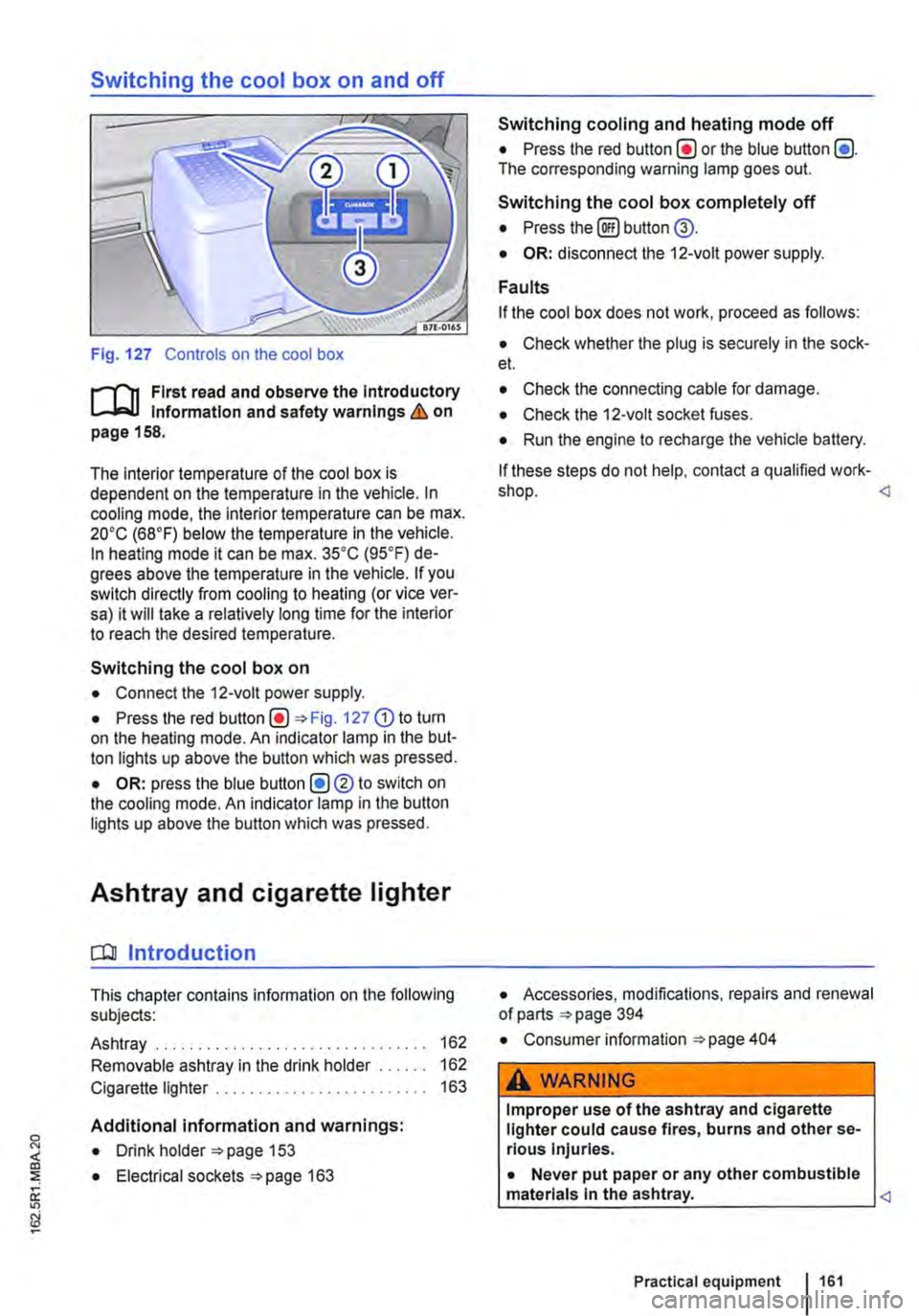
Switching the cool box on and off
Fig. 127 Controls on the cool box
r-f'n First read and observe the Introductory Information and safety warnings & on page 158.
The interior temperature of the cool box is dependent on the temperature in the vehicle. In cooling mode, the interior temperature can be max. 20•c (68°F) below the temperature in the vehicle. In heating mode it can be max. 35•c (95.F) de-grees above the temperature in the vehicle. If you switch directly from cooling to heating (or vice ver-sa) it will take a relatively long time for the interior to reach the desired temperature.
Switching the cool box on
• Connect the 12-volt power supply.
• Press the red Fig. 127 G) to turn on the heating mode. An indicator lamp in the but-ton lights up above the button which was pressed.
• OR: press the blue button (!)®to switch on the cooling mode. An indicator lamp in the button lights up above the button which was pressed.
Ashtray and cigarette lighter
o:n Introduction
This chapter contains information on the following subjects:
Ashtray . . . . . . . . . . . . . . . . . . . 162
Removable ashtray in the drink holder 162
Cigarette lighter . . . . . . . . . . . . . . . . . . . 163
Additional information and warnings:
• Drink holder 153
• Electrical sockets 163
Switching cooling and heating mode off
• Press the red button(!) or the blue button (!). The corresponding warning lamp goes out.
Switching the cool box completely off
• Press the@) button @.
• OR: disconnect the 12-volt power supply.
Faults
If the cool box does not work, proceed as follows:
• Check whether the plug is securely in the sock-et.
• Check the connecting cable for damage.
• Check the 12-volt socket fuses.
• Run the engine to recharge the vehicle battery.
If these steps do not help, contact a qualified work-shop.
• Consumer information 404
A WARNING
Improper use of the ashtray and cigarette lighter could cause fires, burns and other se-rious Injuries.
• Never put paper or any other combustible materials In the ashtray.
Page 163 of 486
Emptying the removable ashtray
• Lift the removable ashtray out of the drink hold-er.
• Open the removable ashtray and empty the cooled ashes into a suitable waste container.
• Once it has been emptied, place the removable ashtray back into the drink holder from above.
r-1'11 First read and observe the introductory L-J.::.IJ information and safety warnings & on page 161.
Depending on the vehicle equipment, a cigarette lighter may be fitted in the drink holder or in the stowage compartment in the dash panel.
• With the ignition switched on, press in the knob on the cigarette lighter.
• Wait for the lighter to pop out.
• Pull out the cigarette lighter and light the tobac-co product on the glowing
• Insert the cigarette lighter back into the socket.
Electrical sockets
c:r:n Introduction
This chapter contains information on the following subjects:
Sockets in the vehicle .......... . 164
Electrical equipment can be connected to the sock-ets in the vehicle.
The connected devices must be in good condition. Do not use faulty devices.
Additional information and warnings:
• Cigarette lighter 161
• Accessories, modifications, repairs and renewal of parts 394
• Consumer information 404
A WARNING
Improper use of the sockets and electrical ac-cessories can cause fires and severe injuries.
A WARNING
Improper use of the cigarette lighter can cause fires, burns and other serious injuries.
• Always use the cigarette lighter properly, and only use it to light tobacco products.
• Never leave children in the vehicle unat-tended. The cigarette lighter can be used when the ignition is switched on.
m The cigarette lighter can also be used as a L!..J 12-volt socket 163.
• Never leave children in the vehicle unat-tended. Sockets and the devices connected to them can be used when the ignition is switched on.
• If the electrical device gets too hot, switch off the device immediately and disconnect it from the socket.
CD
• In order to prevent damage to the electrical system, never connect equipment that gener-ates electricity, such as solar panels or battery chargers for charging the vehicle battery, to the 12-voit socket.
• Only use accessories that have been ap-proved in accordance with current guidelines concerning electromagnetic compatibility. .,..
Practical equipment 163
Page 164 of 486
CD
• In order to avoid damage due to voltage fluctuation, always switch any electrical con-sumers connected to the 12-volt sockets off be-fore switching the ignition or the engine on or off. When the start/stop system automatically switches off and restarts the engine, it Is not necessary to switch off any connected electri-cal consumers.
• Never connect electrical devices requiring more electrical power to a 12-volt socket. The vehicle's electrical system can be damaged If the maximum power output Is exceeded.
• Never feed electricity Into the socket.
Sockets in the vehicle
rT'n First read and observe the Introductory L-lo:J.I information and safety warnings&. on page 163.
There are two separate power circuits in the vehi-cle depending on the equipment:
• 12-volt DC circuit
• 230-volt AC circuit
Maximum power rating
Electrical Maximum power rating socket
12-volt 120 watts
230-volt 2500 watts
Do not exceed the maximum power rating. This al-so applies to the total power consumption of all connected devices if you connect several devices at the same time Introduction on page 163. The power rating of each device is stated on its type plate.
12-volt socket
Electrical equipment can be connected to the 12-volt sockets in the vehicle.
Using electrical appliances with the engine switch-ed off and the ignition switched on will drain the battery. Electrical consumers should therefore only be plugged into the sockets when the engine is running.
To prevent damage due to voltage fluctuation, switch off any connected devices before switching the ignition or engine on or off.
In the vehicle, there are 12-volt sockets in the fol-lowing locations, among others:
164 I Before the journey
Do not leave the engine running when the ve-l?1S hicle is stationary.
m Using electrical appliances with the engine L!..J switched off and the ignition switched on will drain the battery.
m Unshielded devices can cause interference L!..J with radio reception and vehicle electronics.
m Functional problems may occur with some L!..J devices when they are connected to the 230-volt socket due to the lower power output (wat-tage).
• In the stowage compartment on the dash panel under a small cover.
• In the stowage compartment in the dash panel.
• In the side trim panels in the passenger com-partment
• In the luggage compartment.
• In the roof frame of the pop-up roof.
230-volt grounded safety socket
The 230-volt grounded safety socket is supplied via electrical feed from the external socket 192.
The following electrical consumers are supplied from the 230-volt power supply via the external socket:
• Battery charger
• Depending on the vehicle equipment, the 230-volt grounded safety socket is located in the side trim panel behind the left front seat or on the side of the kitchen unit 192.
230-volt Euro socket
The 230-volt Euro socket is supplied via additional batteries or via an inverter and is located in the side trim panel behind the left front seat 192.
A DANGER !
High voltage In the electrical system!
• Never pour any liquid over the socket.
• Do not Insert any Items which will conduct electricity, such as knitting needles, Into the contacts of the 230-volt socket. .,.
Page 169 of 486
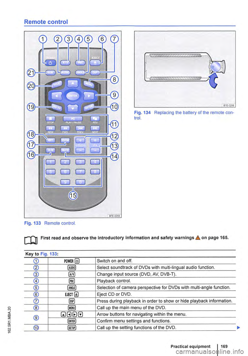
Remote control
Fig. 133 Remote control.
[::::::::::::::::::::::vm
81£.(256
Fig. 134 Replacing the battery of the remote con-trol.
[QJ First read and observe the Introductory Information and safety warnings & on page 165.
Key to Fig 133·
CD POWER@ Switch on and off.
@ Select soundtrack of DVDs with multi-lingual audio function.
® §) Change input source (DVD, AV, DVB-T).
0 @) Playback control.
® Selection of camera perspective for DVDs with multi-angle function.
® EJECT@ Eject CD or DVD.
0 @) Press during playback in order to show or hide playback information.
® Call up the main menu of the DVD.
® QGHtlG Arrow buttons for navigating within the menu.
Confirm menu settings and functions.
@ Call up the setting functions of the DVD.
Practical equipment 169
Page 170 of 486

Key to Fig 133·
8REW8FWD Fast forward or reverse during playback. Press the button repeatedly to increase forward or reverse speed. If the§) button is pressed be-forehand, the slow-motion function has been activated.
@ §)PREY 81£XT Change to previous or next title/chapter.
§) PLAY /PAUSE Press once to start or interrupt playback. Press twice during playback and then press the B or 8 button to jump from scene to scene.
@STOP Stop playback.
Call up settings menu for the screen.
© (!) U/D(CH) Q no function
@ (!)VO!.Q Increase or lower the volume.
®l Switch sound on and off.
@ (ij ... (i) Numerical buttons
® @ Repeat the section selected between the first and second time the button was pressed.
@ Zoom into the current image. Press the button repeatedly to increase the zoom factor and finally to switch the zoom function off.
@ @) Switch repeat function on and off.
@ Skip to a chapter or piece of music.
@ §D Call up the TITLE menu of the DVD.
@ @ Select subtitles of DVDs with a multi-lingual subtitle function.
Replacing the battery
If the remote control unit no longer reacts when you press a button. the battery is empty and must be replaced.
• Slide open the cover on the rear of the remote control unit.
• Using a suitable thin object, lever the battery out of the battery compartment.
• Insert a new battery in the direction of the arrow 134
• Close the cover.
Swallowing batteries with a diameter of 20 mm or other lithium batteries can result in severe or even fatal injuries within a very short period of time.
• Always keep the remote control unit, key ring with batteries, spare batteries, round cells and other batteries that are larger than 20 mm out of the reach of children.
Settings on the LCD screen
rl'11 First read and observe the introductory L-W.f information and safety warnings & on page 165.
170 I Before the journey
• Call for medical help immediately you sus-pect that someone has swallowed a battery.
CD
• The remote control can be damaged if the battery is not changed properly.
• Unsuitable batteries can damage the remote control. Replace discharged batteries only with new batteries of the same voltage rating, size and specification.
• Ensure that the battery Is fitted the right way round.
Dispose of discharged batteries in accord-W ance with regulations governing the protec-tion of the environment.
r::l If the 0 symbol is displayed when you press l!J a button, the button will not function when a CD or DVD is inserted in the slot.
Page 172 of 486
• Press the [ENTER! button to confirm your selec-tion.
• Press the [SETUP! button again to leave the main menu.
The following settings can be made in the subme-nus:
• Picture format.
• Camera perspective.
• Language.
• Subtitles.
• Screen saver.
• Saving the last item played.
Tachograph
o::D Introduction
This chapter contains information on the following subjects:
Notes on the tachograph . . . . . . . . . . . . . . . . . 172
The function and operation of the factory-fitted ta-chograph can be found in an additional operating manual delivered with the vehicle.
If you retro-fit a tachograph to the vehicle, ensure it complies with relevant legislation.
Additional information and warnings:
• Towing a trailer 139
• Accessories. modifications, repairs and renewal of parts 394
Notes on the tachograph
I""'""'J'n First read and observe the Introductory L-lo:.l.l Information given on page 172.
Location
Depending on the model, the factory-fitted tacho-graph could be located in the middle of the dash panel or in a console on the dash panel.
Time
For the time settings, refer to the additional operat-ing instructions for the tachograph.
Please note that in digital tachographs, the time must be displayed in local time. The time on the printouts is always given in UTC (Coordinated Uni-versal Time).
1721 Before the journey
• Various audio settings.
• Colour system.
• Playback control for video COs
• Parental lock 172.
• Reset to default settings.
• Password protection.
Childproof locks
This function is only available in the case of DVDs with restricted access for young people and chil-dren. This menu is used to specify whether a DVD with access restrictions is to be played or whether a password has to be entered first.
m Manipulation of the tachograph and its signal, l.!J and misuse of the tachograph discs can re-sult in prosecution.
The digital tachograph has a buffer battery to pre-vent data loss. The buffer battery can supply power for approx. one year without an external power supply. This function is used if, for example, the digital tachograph is removed from the vehicle and stored or if left in a vehicle with a battery fault or a flat battery.
Legal requirements
By law. the tachograph must be used in: