2020 VOLKSWAGEN TRANSPORTER key battery
[x] Cancel search: key batteryPage 109 of 486

Turn the light switch to the required position 86:
When the Ignition Is switched off
0 The fog lights, dipped beam headlights and side lights are switched off.
,. The orientation lighting can be switched on.
) , The side lights are switched on.
Dipped beam headlights are switched off.
"'D While the vehicle key is in lhe ignition lock, the side lights will stay on.
Fog lights
The indicator lamps or 0$ in the light switch or Instrument cluster indicate that the fog lights are switched on.
• To switch the fog light on, pull the light switch out of the position "" or tD to the first stop.
• To switch the rear fog light 0$ on, pull the light switch out of position ,.,, or gD as far as it will go.
• To switch the fog lights off, press the light switch or move it to position 0.
Signal tones if lights are not switched off
If the key is removed from the ignition lock and the driver door is opened, a signal tone will sound in any of the following situations. This will remind you to switch off the lights as necessary.
Lights and vision -functions
1""1'11 First read and observe the introductory L-lo:.U Information and safety warnings & on page 106.
Parking light
When the parking lights (left and right turn signals) are switched on, the headlight on the correspond-ing side of the vehicle lights up along with the tail light and parts of the tail light cluster. The parking light only lights up when the Ignition is switched off and if the turn signal and main beam lever was in the central position before being operated.
Side lights
If the light switch is in position ;.o; both headlights with side lights light up, along with parts of the rear light cluster, the number plate lighting, the instru-ment cluster lighting and the buttons in the centre console and the dash panel.
If the charge level of the battery is too low, the side lights will switch off automatically &. This pre-vents the vehicle battery from being discharged
When the Ignition Is switched on
Lights switched off or daytime headlights are switched on.
The automatic headlight control and, if applica-ble, the daytime headlights are switched on.
The side lights are switched on.
The dipped beam headlights are switched on.
• If the parking light is switched on 107.
• If the light switch is in position '"'·
• If the light switch is in position iD or 0$ 112.
A WARNING
The side lights or daytime running lights are not bright enough to Illuminate the road ahead and to ensure that other road users are able to see you.
• Always switch the dipped beam head-lights on if it is dark, raining or visibility Is
completely and thus allows for still starting the en-gine 366, Automatic switch-off for electri-cal consumers.
Daytime running lights
There are separate lights in the headlights for the daytime running lights.
Only the separate lights light up when the daytime running lights are switched on &.
The daytime running lights are switched on when the ignition is switched on if the light switch is in position 0 or AUTO.
If the light switch is in position AUTO, a rain sensor will switch the dipped beam and the lighting in the instruments and switches on and off automatically.
The daytime running lights cannot be switched on or off manually. ,._
Lights and vision 1109
Page 114 of 486

Interior and reading lights
0 ( )
ITT·0116
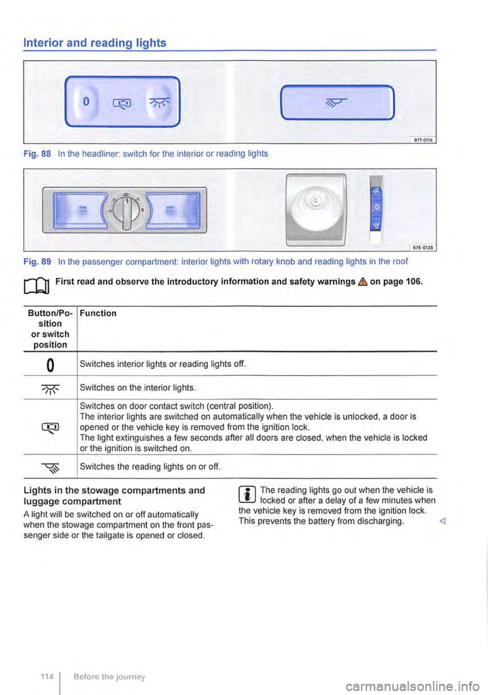
Fig. 88 In the headliner: switch for the interior or reading lights
871·01ll
Fig. 89 In the passenger compartment: interior lights with rotary knob and reading lights in the roof
[Q] First read and observe the Introductory information and safety warnings&. on page 106.
Button/Po-Function sition or switch position
0 Switches interior lights or reading lights off.
Switches on the interior lights.
Switches on door contact switch (central position). The interior lights are switched on automatically when the vehicle is unlocked, a door is opened or the vehicle key is removed from the ignition lock. The light extinguishes a few seconds after all doors are closed, when the vehicle is locked or the ignition is switched on.
Switches the reading lights on or off.
Lights in the stowage compartments and luggage compartment
A light will be switched on or off automatically when the stowage compartment on the front pas-senger side or the tailgate is opened or closed.
1141 Before the journey
m The reading lights go out when the vehicle is W locked or after a delay of a few minutes when the vehicle key is removed from the ignition lock. This prevents the battery from discharging.
Page 145 of 486

Key to diagram Fig. 114:
Pin Meaning
8 Reversing light
9 Permanent live
10 Charging cable plus
11 Earth pin 10, charging cable
12 Not assigned
13 Earth pin 9, permanent live
Trailer socket
A 13-pin trailer socket makes the electrical connec-tion between the towing vehicle and the trailer. When the engine is running, electrical consumers in the trailer are supplied with voltage (charging ca-ble) via the electrical connection (pin 10 of the trail-er socket). If required, the charging cable charges the caravan's battery.
When a trailer is electrically detected, electrical consumers in the trailer are supplied with voltage (permanent live) via the electrical connection (pin 9). Permanent live supplies a trailer's interior lighting for example. Electrical consumers such as a caravan refrigerator are supplied with voltage on-ly when the engine is running (pin 1 0).
To avoid overloading the electrical system, do not inter-connect the three earth wires (pins 3, 11 and 13).
If the trailer has a 7 -pin plug you will need to use a suitable adapter cable. Pin 10 (charging cable) is then without function.
Emergency breakaway cable
Always fasten the trailer's emergency breakaway cable properly to the towing vehicle. Leave enough slack in the emergency breakaway cable so that the vehicle can still drive around corners. However the emergency breakaway cable should not drag along the ground while you are driving.
Trailer rear lights
Ensure that the trailer lights work properly and meet legal requirements. Do not exceed the maxi-mum power consumption for the trailer 142.
Connection to the anti-theft alarm
The trailer is integrated in the anti-theft system if the following conditions are fulfilled:
• When the vehicle has a factory-fitted anti-theft alarm and a factory-fitted towing bracket.
• When the trailer is electrically connected to the towing vehicle via the trailer socket.
• When the vehicle and trailer electric systems are functional, fault-free and undamaged.
• When the vehicle is locked with the vehicle key and the anti-theft alarm is active.
When the vehicle is locked, the alarm will be trig-gered as soon as the electrical connection to the trailer is interrupted.
Always switch off the anti-theft alarm when a trailer is being hitched or unhitched. The tilt sensor could otherwise trigger an alarm unnecessarily.
Trailer with LED rear lights
For technical reasons, trailers with LED tail lights cannot be integrated into the anti-theft alarm sys-tem.
When the vehicle is locked, the alarm is not trig-gered as soon as the electrical connection to the trailer with LED rear lights is interrupted.
A WARNING
Any electrical cables that are not connected properly could cause a power surge to the trailer. This could cause faults tn the entire vehicle electronics system and also lead to accidents and serious Injuries.
• All work on the electric system should be carried out by a qualified workshop.
• Never connect the trailer's electrical sys-tem directly to the electrical connections of the tail lights or to other sources of electrici-ty.
CD
If you park the trailer using the support wheel or other trailer supports, disconnect the trailer from the vehicle. The vehicle could rock up and down if the load changes or if there is damage to the tyres. If this happens, a great deal of force will be exerted on the towing bracket and trailer, which could lead to damage to the vehi-cle and trailer.
CD
Maximum power consumption of the trailer should not be exceeded. Otherwise, the vehicle electrical system could be damaged.
m If there is a fault in the vehicle or trailer elec-L.:!.J trical systems or in the anti-theft alarm, have the systems checked by a qualified workshop.
m If the engine is not running and electrical L.:!.J equipment is switched on in the trailer via the trailer socket, the vehicle battery will discharge. .,.
Transporting Items 145
Page 169 of 486

Remote control
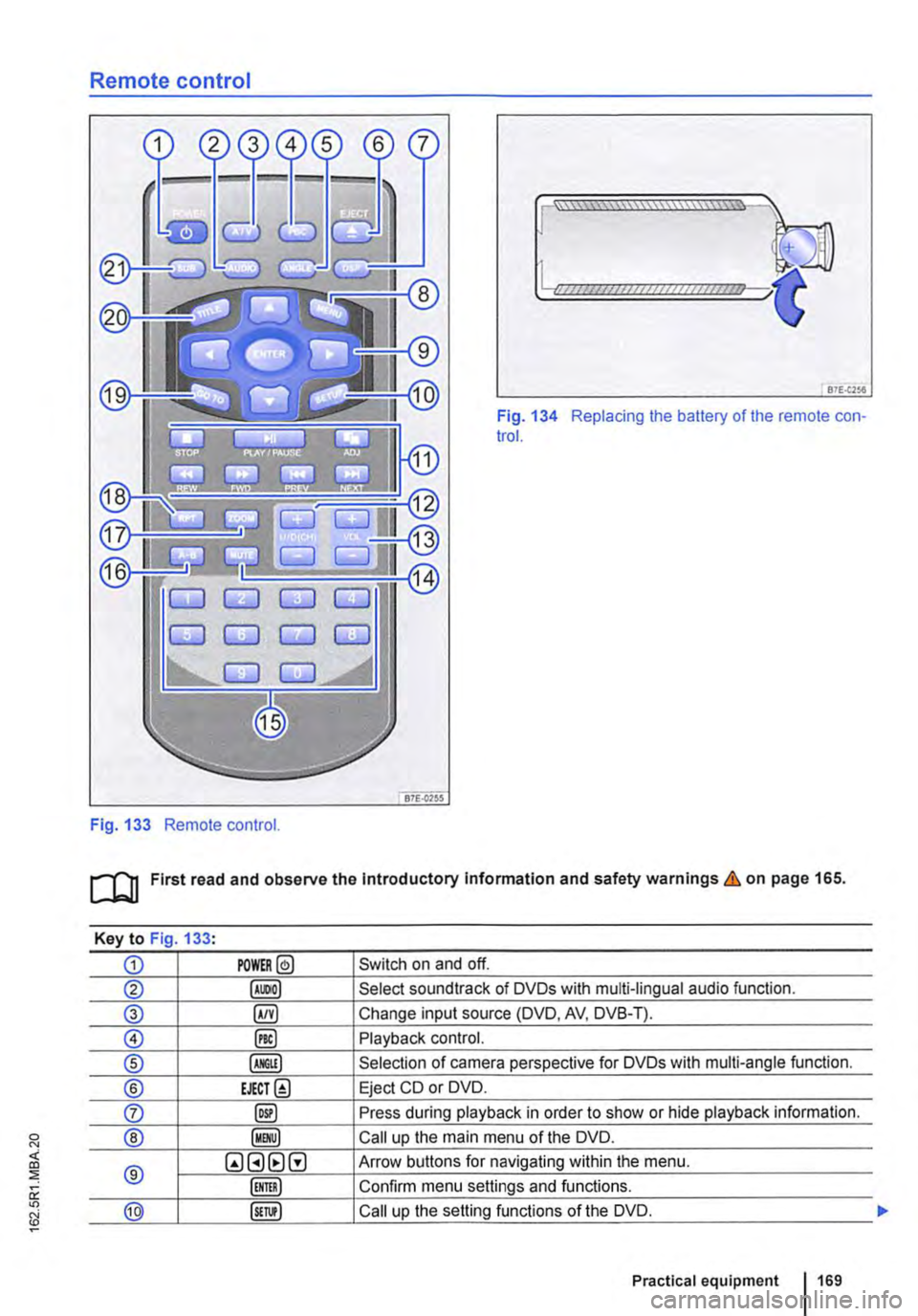
Fig. 133 Remote control.
[::::::::::::::::::::::vm
81£.(256
Fig. 134 Replacing the battery of the remote con-trol.
[QJ First read and observe the Introductory Information and safety warnings & on page 165.
Key to Fig 133·
CD POWER@ Switch on and off.
@ Select soundtrack of DVDs with multi-lingual audio function.
® §) Change input source (DVD, AV, DVB-T).
0 @) Playback control.
® Selection of camera perspective for DVDs with multi-angle function.
® EJECT@ Eject CD or DVD.
0 @) Press during playback in order to show or hide playback information.
® Call up the main menu of the DVD.
® QGHtlG Arrow buttons for navigating within the menu.
Confirm menu settings and functions.
@ Call up the setting functions of the DVD.
Practical equipment 169
Page 170 of 486

Key to Fig 133·
8REW8FWD Fast forward or reverse during playback. Press the button repeatedly to increase forward or reverse speed. If the§) button is pressed be-forehand, the slow-motion function has been activated.
@ §)PREY 81£XT Change to previous or next title/chapter.
§) PLAY /PAUSE Press once to start or interrupt playback. Press twice during playback and then press the B or 8 button to jump from scene to scene.
@STOP Stop playback.
Call up settings menu for the screen.
© (!) U/D(CH) Q no function
@ (!)VO!.Q Increase or lower the volume.
®l Switch sound on and off.
@ (ij ... (i) Numerical buttons
® @ Repeat the section selected between the first and second time the button was pressed.
@ Zoom into the current image. Press the button repeatedly to increase the zoom factor and finally to switch the zoom function off.
@ @) Switch repeat function on and off.
@ Skip to a chapter or piece of music.
@ §D Call up the TITLE menu of the DVD.
@ @ Select subtitles of DVDs with a multi-lingual subtitle function.
Replacing the battery
If the remote control unit no longer reacts when you press a button. the battery is empty and must be replaced.
• Slide open the cover on the rear of the remote control unit.
• Using a suitable thin object, lever the battery out of the battery compartment.
• Insert a new battery in the direction of the arrow 134
• Close the cover.
Swallowing batteries with a diameter of 20 mm or other lithium batteries can result in severe or even fatal injuries within a very short period of time.
• Always keep the remote control unit, key ring with batteries, spare batteries, round cells and other batteries that are larger than 20 mm out of the reach of children.
Settings on the LCD screen
rl'11 First read and observe the introductory L-W.f information and safety warnings & on page 165.
170 I Before the journey
• Call for medical help immediately you sus-pect that someone has swallowed a battery.
CD
• The remote control can be damaged if the battery is not changed properly.
• Unsuitable batteries can damage the remote control. Replace discharged batteries only with new batteries of the same voltage rating, size and specification.
• Ensure that the battery Is fitted the right way round.
Dispose of discharged batteries in accord-W ance with regulations governing the protec-tion of the environment.
r::l If the 0 symbol is displayed when you press l!J a button, the button will not function when a CD or DVD is inserted in the slot.
Page 192 of 486

Equipment, California
Vehicle overview, California
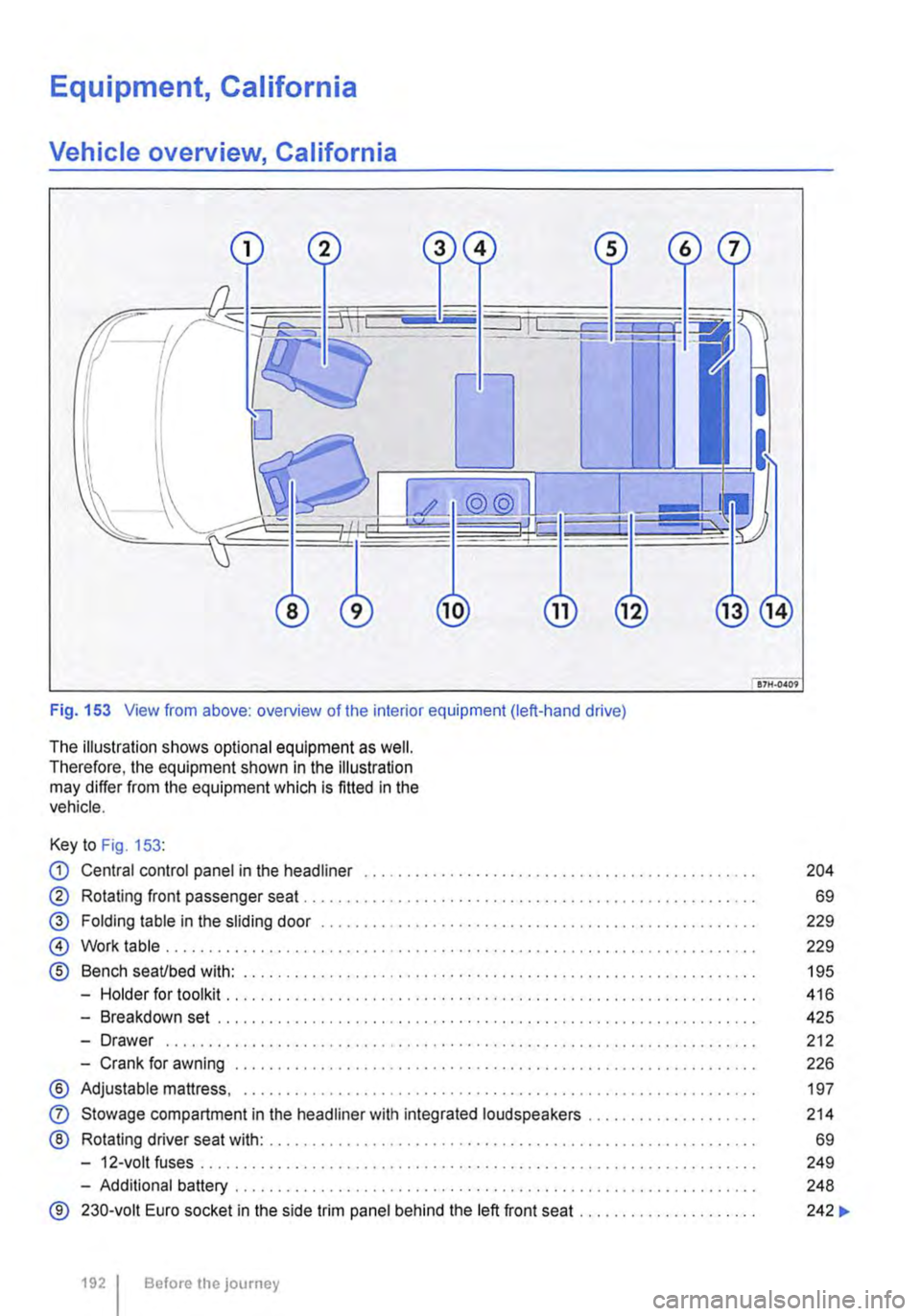
Fig. 153 View from above: overview of the interior equipment (left-hand drive)
The illustration shows optional equipment as well. Therefore, the equipment shown in the illustration may differ from the equipment which is fitted in the vehicle.
Key to Fig. 153:
CD Central control panel in the headliner . . . . . . . . . . . . . . . . . . . . . . . . . • . . . . . . . . . . . . . . . . . . . . 204
® Rotating front passenger seat . . . . . . . . . . . . . . . . . . . . . . . . . . . . . . . . . . . . . . . . . . . . . . . . . . . 69
@ Folding table in the sliding door . . . . . . . . . . . . . . . . . . . . . . . . . . . . . . . . . . . . . . . . . . . . . . 229
@ Work table . . . . . . . . . . . . . . . . . . . . . . . . . . . . . . . . . . . . . . . . . . . . . . . . . . . . . . . . . . . . . . . . . . 229
® Bench seaUbed with: . . . . . . . . . . . . . . . . . . . . . . . . . . . . . . . . . . . . . . . . . . . . . . . . . . . 195
-Holder for toolkit .......... .
-Breakdown set ..................................................... .
-Drawer ................................................................. · · ·
-Crank for awning .............................................•..............
® Adjustable mattress, ............................................•...............
0
®
Stowage compartment in the headliner with integrated loudspeakers ................... .
Rotating driver seat with: ........................................................ .
-12-volt fuses ..
-Additional battery ........... .
® 230-volt Euro socket in the side trim panel behind the left front seat ..
1921 Before the journey
416
425
212
226
197
214
69
249
248
242 ...
Page 193 of 486

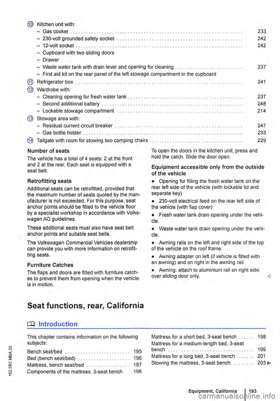
@ Kitchen unit with:
-Gas cooker ................................... . 233
242
242
-230-volt grounded safety socket ................. .
-12-volt socket .............................•..................................
-Cupboard with two sliding doors
-Drawer
-Waste water tank with drain lever and opening for cleaning ...... . 237
-First aid kit on the rear panel of the left stowage compartment in the cupboard
@ Refrigerator box ...
@ Wardrobe with:
241
-Cleaning opening for fresh water tank . . . . . . . . . . . . . . . . . . . . . . . . . . . . . . . . . . . . . . . 237
-Second additional battery . . . . . ........ , . . . . . . . . . . . . . . . . . . . . . . . . . . 248
-Lockable stowage compartment . . . . . . . . . . . . . . . . . . . . . . . . . . . . . . . . . . . . . . . . . . . . . . . . 214
@ Stowage area with:
-Residual current circuit breaker ............... , ...... . 247
233
229
-Gas bottle holder .................. .
® Tailgate with room for stowing two camping chairs
Number of seats
The vehicle has a total of 4 seats: 2 at the front and 2 at the rear. Each seat is equipped with a seat belt.
Retrofitting seats
Additional seats can be retrofitted, provided that the maximum number of seats quoted by the man-ufacturer is not exceeded. For this purpose, seat anchor points should be fitted to the vehicle floor by a specialist workshop in accordance with Volks-wagen AG guidelines.
These additional seats must also have seat belt anchor points and suitable seat belts.
The Volkswagen Commercial Vehicles dealership can provide you with more information on retrofit-ting seats.
Furniture Catches
The flaps and doors are fitted with furniture catch-es to prevent them from opening when the vehicle is in motion.
Seat functions, rear, California
ClJ Introduction
This chapter contains information on the following subjects:
Bench seat/bed . . . . . . . . . . . . . . . . . . . . • • . . . 195
Bed (bench seat/bed) . . . . . . . . . . . 196 Mattress, bench seat/bed . . . . . . . . . . . . . . . . . 197
Components of the mattress, 3-seat bench . . 198
To open the doors in the kitchen unit, press and hold the catch. Slide the door open.
Equipment accessible only from the outside of the vehicle
• Opening for filling the fresh water tank on the rear left side of the vehicle (with lockable lid and separate key)
• 230-volt electrical feed on the rear left side of the vehicle (with flap cover)
• Fresh water tank drain opening under the vehi-cle.
• Waste water tank drain opening under the vehi-cle.
• Awning rails on the left and right side of the top of the vehicle on the roof frame.
• Awning adapter on left (if vehicle is fitted with an awning) and on right in the awning rail.
• Awning: attach to aluminium rail on right side over sliding door only.
Mattress for a medium-length bed, 3-seat bench . . . . . . . . . . . . . . . . . . . . . . . . . . . . 199 Mattress for a long bed, 3-seat bench . . . . . . . 201 Stowing the mattress, 3-seat bench . . . . . . . . 203 .,..
Equipment, California 1193
Page 281 of 486

Steering
CJ:n Introduction
This chapter contains information on the following subjects:
Information on steering . . . . . . . . . . . . . . . . . . . 281
Additional information and warnings:
• Starting and stopping the engine 257
• Battery 362
• Tow-starting and towing 446
Information on steering
r--f"n First read and observe the introductory L-la.LI infonmation and safety warnings & on page 281.
Locking the steering wheel
• When the vehicle key has been removed, turn the steering wheel slightly until you hear the lock-ing pin engage.
The steering should be locked every time you leave the vehicle to make il more difficult for the vehicle to be stolen.
Unlocking the steering wheel
• Turn the steering wheel slightly to lake the load off the steering lock mechanism. Hold the steering wheel in this position and tu m the vehicle key clockwise out of position 217 @.
A WARNING
If the power steering is not working, the steering wheel is difficult to turn, which makes it difficult to steer the vehicle.
• The power steering only functions when the engine Is running.
• Never allow the vehicle to roll if the engine is switched off.
• Never remove the vehicle key from the ig-nition lock when the vehicle is in motion. The steering lock may be activated and you will no longer be able to steer the vehicle.
With power steering, the steering assistance is au-tomatically matched to vehicle speed, the steering wheel torque and the steering wheel angle. The power steering will only function when the engine is running.
You will need considerably more strength than nor-mal to steer the vehicle if lhe power steering is re-duced or has failed completely.