2020 Ram ProMaster City key battery
[x] Cancel search: key batteryPage 5 of 350

2
INTRODUCTION
INTRODUCTION .............................................................. 10
HOW TO USE THIS MANUAL ....................................... 11
Essential Information .................................................... 11
Symbols ........................................................................... 11
WARNINGS AND CAUTIONS ....................................... 12
VAN CONVERSIONS/CAMPERS ................................ 12
VEHICLE MODIFICATIONS/ALTERATIONS ........... 12
GETTING TO KNOW YOUR VEHICLE
KEYS ..................................................................................... 13
Key Fob ........................................................................... 13
To Lock The Doors ........................................................ 15
Sound Horn With Lock................................................. 15
Key Fob Battery Replacement...................................... 15
Programming Additional Key Fobs .......................... 16
General Information ...................................................... 16
IGNITION SWITCH .......................................................... 17
Ignition Key Removal ................................................. 17
Key-In-Ignition Reminder ........................................... 18
SENTRY KEY ..................................................................... 19
Replacement Keys ........................................................ 19
General Information ...................................................... 20
VEHICLE SECURITY ALARM — IF EQUIPPED .........21
To Arm The System .......................................................21
To Disarm The System ..................................................21
Rearming Of The System ..............................................21
Security System Manual Override ..............................21
DOORS .................................................................................22
Door Locks .....................................................................22
Sliding Side Door ...........................................................24
Child Lock System .........................................................27
Double Rear Swing Doors ............................................28
SEATS ................................................................................29
Manual Adjustment (Front Seats) ...............................30
Heated Seats — If Equipped ........................................32
Folding Rear Seat — If Equipped ................................33
HEAD RESTRAINTS .........................................................34
Front Adjustment...........................................................35
Rear Adjustment ............................................................35
Front Removal ................................................................36
Rear Removal .................................................................37
STEERING WHEEL ............................................................38
Tilt/Telescoping Steering Column ...........................38
MIRRORS ............................................................................38
Inside Day/Night Mirror — If Equipped ..................38
Outside Mirrors .............................................................39
Power Outside Mirrors — If Equipped .....................41
Vanity Mirror .................................................................42
2020_RAM_PROMASTER_CITY_OM_USA=GUID-7B6A7FCA-79B0-423F-95C5-ED2A949C3D13=1=en=.book Page 2
Page 9 of 350

6
DRIVING TIPS................................................................... 196
Driving On Slippery Surfaces ................................... 196
Driving Through Water ............................................. 197
IN CASE OF EMERGENCY
HAZARD WARNING FLASHERS .............................. 199
BULB REPLACEMENT .................................................. 200
Replacement Bulbs ................................................... 200
Replacing Exterior Bulbs ............................................ 201
Replacing Interior Bulbs ............................................. 203
FUSES.................................................................................. 206
Underhood Fuses......................................................... 206
Interior Fuses................................................................ 209
Central Unit Fuse Panel .............................................. 211
JACKING AND TIRE CHANGING ............................... 212
Jack Location — If Equipped ..................................... 212
Removing The Spare Tire — If Equipped ................ 213
Preparations For Jacking ........................................... 217
Jacking Instructions ..................................................... 218
Vehicles With Alloy Wheels ...................................... 224
Vehicles Equipped With Wheel Covers ................... 226
TIRE SERVICE KIT — IF EQUIPPED ........................... 227
Tire Service Kit Storage .............................................. 227
Tire Service Kit Usage ................................................. 227
JUMP STARTING..............................................................231
Preparations For Jump Starting ................................. 231
Jump Starting Procedure ............................................232
IF YOUR ENGINE OVERHEATS ..................................234
IGNITION KEY REMOVAL OVERRIDE ......................235
GEAR SELECTOR OVERRIDE .....................................236
FREEING A STUCK VEHICLE ......................................237
TOWING A DISABLED VEHICLE ...............................238
ENHANCED ACCIDENT RESPONSE
SYSTEM (EARS) ...............................................................240
EVENT DATA RECORDER (EDR)................................. 240
SERVICING AND MAINTENANCE
SCHEDULED SERVICING .............................................241
Maintenance Plan ........................................................242
ENGINE COMPARTMENT .......................................... 245
Engine Compartment — 2.4L ....................................245
Checking Oil Level ......................................................246
Adding Washer Fluid .................................................246
Maintenance-Free Battery .......................................... 247
Pressure Washing ........................................................248
2020_RAM_PROMASTER_CITY_OM_USA=GUID-7B6A7FCA-79B0-423F-95C5-ED2A949C3D13=1=en=.book Page 6
Page 18 of 350

GETTING TO KNOW YOUR VEHICLE 15
To Lock The Doors
Push and release the lock button on the key fob to lock all
doors. The turn signal lights will flash to acknowledge the
signal. If a door is open, the turn signal lights will flash at an
increased rate. This is to indicate that a door is still open.
Horn activation settings after a Radio Frequency (RF) lock
command can be adjusted manually. Refer to “Uconnect
Settings” in “Multimedia” for further information.
Locking Doors With A Key
1. Insert the key with either side up.
2. Turn the key to the right to lock the door.
3. Turn the key to the left to unlock the door.
Refer to “Dealer Service” in “Servicing And Maintenance”
for maintenance procedures.
Sound Horn With Lock
This feature will cause the horn to chirp when the doors are
locked with the key fob. This feature can be turned on or
turned off. To change the current setting, refer to “Uconnect
Settings” in “Multimedia” for further information.
Key Fob Battery Replacement
NOTE:
Perchlorate Material – special handling may apply. See
www.dtsc.ca.gov/hazardouswaste/perchlorate.
The recommended replacement battery is CR2032.
1. Push the mechanical key release button and release the mechanical key to access the battery case screw located on
the side of the key fob.
2. Rotate the screw located on the side of the key fob using a small screwdriver.
2
2020_RAM_PROMASTER_CITY_OM_USA=GUID-7B6A7FCA-79B0-423F-95C5-ED2A949C3D13=1=en=.book Page 15
Page 19 of 350

16 GETTING TO KNOW YOUR VEHICLE
Key Fob Screw Location
3. Take out the battery case. Remove and replace the battery observing its polarity.
4. Refit the battery case inside the key fob and turn the screw to lock it into place.
Programming Additional Key Fobs
Programming the key fob may be performed by an autho -
rized dealer.
NOTE:
Once a key fob is programmed to a vehicle, it cannot be
re-purposed and reprogrammed to another vehicle.
General Information
The following regulatory statement applies to all Radio
Frequency (RF) devices equipped in this vehicle:
This device complies with Part 15 of the FCC Rules and with
Innovation, Science and Economic Development Canada
license-exempt RSS standard(s). Operation is subject to the
following two conditions:
1. This device may not cause harmful interference, and
2. This device must accept any interference received, including interference that may cause undesired opera -
tion.
2020_RAM_PROMASTER_CITY_OM_USA=GUID-7B6A7FCA-79B0-423F-95C5-ED2A949C3D13=1=en=.book Page 16
Page 73 of 350

70 GETTING TO KNOW YOUR VEHICLE
Power Outlets
Your vehicle is equipped with 12 Volt (15 Amp) power
outlets that can be used to power cellular phones, small elec-
tronics and other low powered electrical accessories. The
power outlets are labeled with either a “key” or a “battery”
symbol to indicate how the outlet is powered. Power outlets
labeled with a “key” are powered when the ignition is in the
MAR (ACC/ON/RUN) position, while the outlets labeled
with a “battery” are connected directly to the battery and
powered at all times.
NOTE:
• All accessories connected to the “battery” powered outlets should be removed or turned off when the vehicle is not in
use to protect the battery against discharge. Driver And Front Passenger Power Outlets
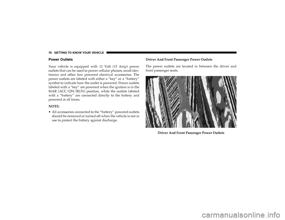
The power outlets are located in between the driver and
front passenger seats.
Driver And Front Passenger Power Outlets
2020_RAM_PROMASTER_CITY_OM_USA=GUID-7B6A7FCA-79B0-423F-95C5-ED2A949C3D13=1=en=.book Page 70
Page 74 of 350

GETTING TO KNOW YOUR VEHICLE 71
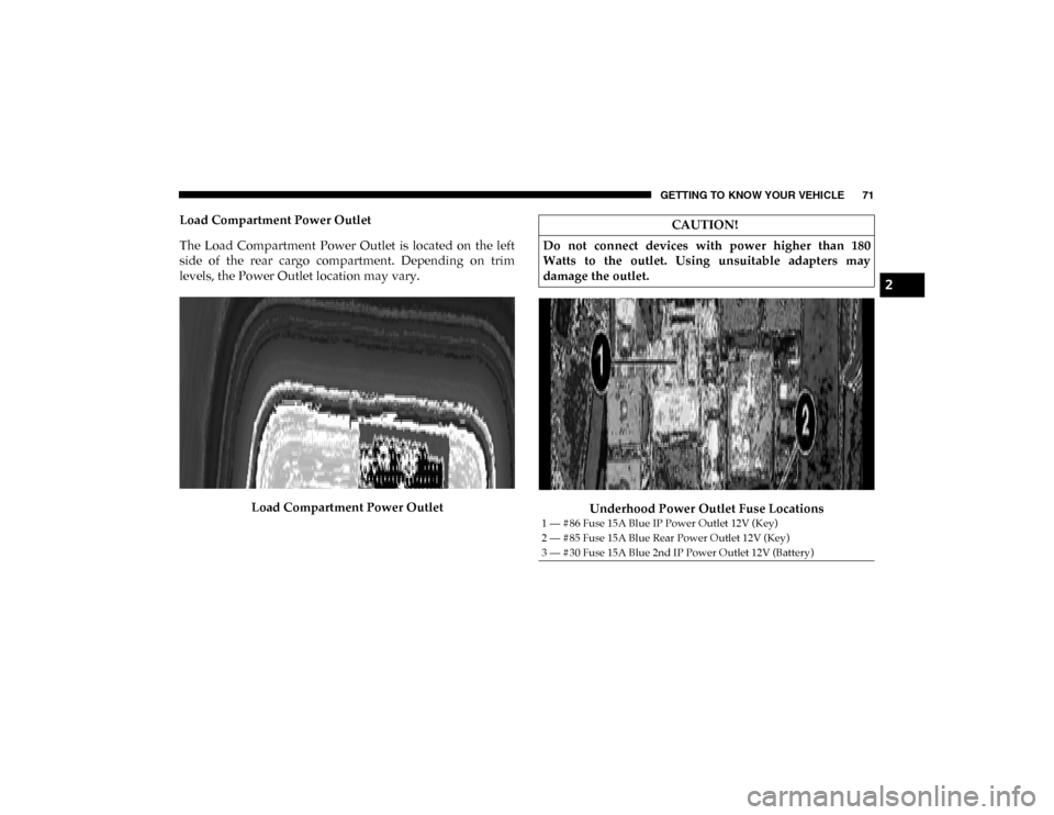
Load Compartment Power Outlet
The Load Compartment Power Outlet is located on the left
side of the rear cargo compartment. Depending on trim
levels, the Power Outlet location may vary.Load Compartment Power Outlet Underhood Power Outlet Fuse LocationsCAUTION!
Do not connect devices with power higher than 180
Watts to the outlet. Using unsuitable adapters may
damage the outlet.
1 — #86 Fuse 15A Blue IP Power Outlet 12V (Key)
2 — #85 Fuse 15A Blue Rear Power Outlet 12V (Key)
3 — #30 Fuse 15A Blue 2nd IP Power Outlet 12V (Battery)
2
2020_RAM_PROMASTER_CITY_OM_USA=GUID-7B6A7FCA-79B0-423F-95C5-ED2A949C3D13=1=en=.book Page 71
Page 134 of 350

SAFETY 131
Enhanced Accident Response System
In the event of an impact, if the communication network
remains intact, and the power remains intact, depending on
the nature of the event, the ORC will determine whether to
have the Enhanced Accident Response System perform the
following functions:
• Cut off fuel to the engine (if equipped)
• Cut off battery power to the electric motor (if equipped)
• Flash hazard lights as long as the battery has power
• Turn on the interior lights, which remain on as long as thebattery has power or for 15 minutes from the intervention
of the Enhanced Accident Response System
• Unlock the power door locks
Your vehicle may also be designed to perform any of these
other functions in response to the Enhanced Accident
Response System:
• Turn off the Fuel Filter Heater, Turn off the HVAC Blower Motor, Close the HVAC Circulation Door • Cut off battery power to the:
• Engine
• Electric Motor (if equipped)
• Electric Power Steering
• Brake booster
• Automatic transmission gear selector
• Horn
• Front wiper
NOTE:
After an accident, remember to cycle the ignition to the STOP
(OFF/LOCK) position and remove the key from the ignition
switch to avoid draining the battery. Carefully check the
vehicle for fuel leaks in the engine compartment and on the
ground near the engine compartment and fuel tank before
resetting the system and starting the engine. If there are no
fuel leaks or damage to the vehicle electrical devices (e.g.
headlights) after an accident, reset the system by following
the procedure described below. If you have any doubt,
contact an authorized dealer.
4
2020_RAM_PROMASTER_CITY_OM_USA=GUID-7B6A7FCA-79B0-423F-95C5-ED2A949C3D13=1=en=.book Page 131
Page 161 of 350

158 STARTING AND OPERATING
Cold Weather Operation
To ensure reliable starting at low temperatures, use of an
externally powered electric engine block heater (available
from your authorized dealer) is recommended.
To prevent possible engine damage while starting at low
temperatures, this vehicle will inhibit engine cranking when
the ambient temperature is less than -31°F (-35° C) and the oil
temperature sensor reading indicates an engine block heater
has not been used. The message “plug in engine heater” will
be displayed in the instrument cluster when the ambient
temperature is below -25°F (-32° C) at the time the engine is
shut off as a reminder.
Extended Park Starting
NOTE:
Extended Park condition occurs when the vehicle has not
been started or driven for at least 30 days.
1. Install a battery charger or jumper cables to the battery toensure a full battery charge during the crank cycle.
2. Cycle the ignition to the AVV/”START” position and release it when the engine starts. 3. If the engine fails to start within ten seconds, cycle the
ignition to the STOP (OFF/LOCK) position, wait five
seconds to allow the starter to cool, then repeat the
Extended Park Starting procedure.
4. If the engine fails to start after eight attempts, allow the starter to cool for at least 10 minutes, then repeat the
procedure.
If Engine Fails To Start
If the engine fails to start after you have followed the "Normal
Starting" or "Extreme Cold Weather" procedure, and has not
experienced an extended park condition as identified in
"Extended Park Starting" procedure it may be flooded. Push
the accelerator pedal all the way to the floor and hold it there.
Crank the engine for no more than 15 seconds. This should
clear any excess fuel in case the engine is flooded. Leave the
ignition key in the MAR position, release the accelerator pedal
and repeat the “Normal Starting” procedure.
CAUTION!
To prevent damage to the starter, do not crank
continuously for more than 10 seconds at a time. Wait 10
to 15 seconds before trying again.
2020_RAM_PROMASTER_CITY_OM_USA=GUID-7B6A7FCA-79B0-423F-95C5-ED2A949C3D13=1=en=.book Page 158