2020 PEUGEOT 5008 change wheel
[x] Cancel search: change wheelPage 153 of 308
151
Driving
6Operation
Once the system identifies a risk of the vehicle
involuntarily crossing one of the lane markings
detected, it makes the correction to the trajectory
required to return the vehicle to its initial path.
The driver will notice a turning movement of the
steering wheel.
This warning lamp flashes during trajectory correction.
The driver can prevent the correction by keeping a firm grip on the wheel (during
an avoiding manoeuvre, for example).
The correction is interrupted if the direction
indicators are operated.
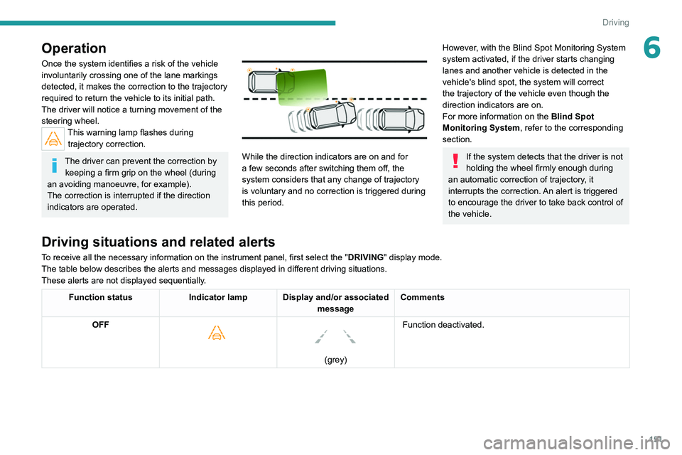
While the direction indicators are on and for
a few seconds after switching them off, the
system considers that any change of trajectory
is voluntary and no correction is triggered during
this period.
However, with the Blind Spot Monitoring System
system activated, if the driver starts changing
lanes and another vehicle is detected in the
vehicle's blind spot, the system will correct
the trajectory of the vehicle even though the
direction indicators are on.
For more information on the Blind Spot
Monitoring System , refer to the corresponding
section.
If the system detects that the driver is not
holding the wheel firmly enough during
an automatic correction of trajectory, it
interrupts the correction. An alert is triggered
to encourage the driver to take back control of
the vehicle.
Driving situations and related alerts
To receive all the necessary information on the instrument panel, first select the " DRIVING" display mode.
The table below describes the alerts and messages displayed in different driving situations.
These alerts are not displayed sequentially.
Function status Indicator lamp Display and/or associated
messageComments
OFF
(grey)
Function deactivated.
Page 160 of 308
158
Driving
Obstacles may appear further away than
they actually are.
It is important to monitor the sides of the
vehicle during the manoeuvre, using the
mirrors.
Parking sensors also provide additional
information about the area around the vehicle.
180° view
The 180° view facilitates reversing out of a
parking space, making it possible to see the
approach of vehicles, pedestrians and cyclists.
This view is not recommended for carrying out a
complete manoeuvre.
It features 3 areas: left A, centre B and right C.
the system is activated when the vehicle has
already moved, the view from above can be fully
displayed.
Visiopark 1
Rear vision
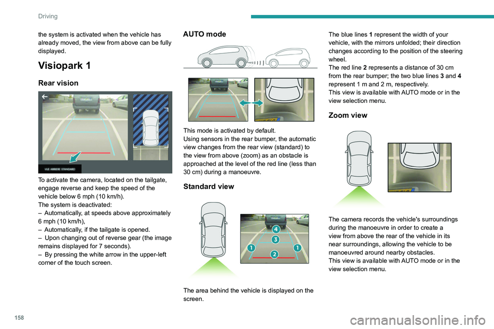
To activate the camera, located on the tailgate,
engage reverse and keep the speed of the
vehicle below 6 mph (10
km/h).
The system is deactivated:
–
Automatically
, at speeds above approximately
6 mph (10
km/h),
–
Automatically
, if the tailgate is opened.
–
Upon changing out of reverse gear (the image
remains displayed for 7
seconds).
–
By pressing the white arrow in the upper-left
corner of the touch screen.
AUTO mode
This mode is activated by default.
Using sensors in the rear bumper, the automatic
view changes from the rear view (standard) to
the view from above (zoom) as an obstacle is
approached at the level of the red line (less than
30
cm) during a manoeuvre.
Standard view
The area behind the vehicle is displayed on the
screen. The blue lines
1 represent the width of your
vehicle, with the mirrors unfolded; their direction
changes according to the position of the steering
wheel.
The red line 2 represents a distance of 30 cm
from the rear bumper; the two blue lines 3 and 4
represent 1 m and 2 m, respectively.
This view is available with AUTO mode or in the
view selection menu.
Zoom view
The camera records the vehicle's surroundings
during the manoeuvre in order to create a
view from above the rear of the vehicle in its
near surroundings, allowing the vehicle to be
manoeuvred around nearby obstacles.
This view is available with AUTO mode or in the
view selection menu.
Page 162 of 308
160
Driving
180° view
The 180° view assists with exiting from a parking
space in forward gear, making it possible to
see the approach of vehicles, pedestrians and
cyclists.
This view is not recommended for carrying out a
complete manoeuvre.
It consists of 3 areas: left A, centre B and right
C.
This view is available only from the view
selection menu.
Park Assist
Refer to the General recommendations on the
use of driving and manoeuvring aids .
gear engaged, or with rear vision, if reverse is
engaged.
The system is deactivated:
–
Automatically above about 19 mph (30
km/h)
(the image disappears temporarily from 12 mph
(20
km/h)).
–
By pressing the white arrow in the upper-left
corner of the touch screen.
AUTO mode
This mode is activated by default.
Using sensors in the front bumper, the automatic
view changes from the front view (standard) to
the view from above (zoom) as an obstacle is
approached during a manoeuvre.
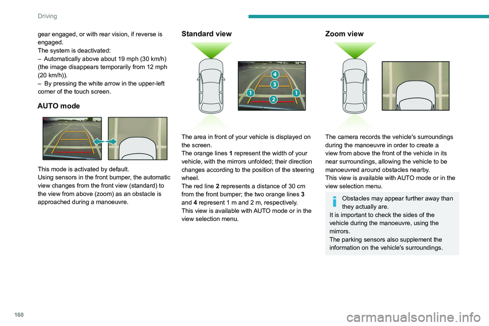
Standard view
The area in front of your vehicle is displayed on
the screen.
The orange lines 1 represent the width of your
vehicle, with the mirrors unfolded; their direction
changes according to the position of the steering
wheel.
The red line 2 represents a distance of 30 cm
from the front bumper; the two orange lines 3
and 4 represent 1 m and 2 m, respectively.
This view is available with AUTO mode or in the
view selection menu.
Zoom view
The camera records the vehicle's surroundings
during the manoeuvre in order to create a
view from above the front of the vehicle in its
near surroundings, allowing the vehicle to be
manoeuvred around obstacles nearby.
This view is available with AUTO mode or in the
view selection menu.
Obstacles may appear further away than
they actually are.
It is important to check the sides of the
vehicle during the manoeuvre, using the
mirrors.
The parking sensors also supplement the
information on the vehicle's surroundings.
Page 178 of 308
176
Practical information
Fitting directly to the roof
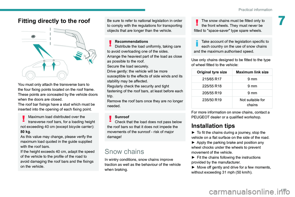
You must only attach the transverse bars to
the four fixing points located on the roof frame.
These points are concealed by the vehicle doors
when the doors are closed.
The roof bar fixings have a stud which must be
inserted into the opening of each fixing point.
Maximum load distributed over the
transverse roof bars, for a loading height
not exceeding 40 cm (except bicycle carrier):
80 kg.
As this value may change, please verify the
maximum load quoted in the guide supplied
with the roof bars.
If the height exceeds 40 cm, adapt the speed
of the vehicle to the profile of the road to
avoid damaging the roof bars and the fixings
on the vehicle.
► Insert the key into the lock 7.
► Open the lock using the key .
► Hold the towball 5 firmly in one hand; using
the other hand, pull and turn the wheel 6 fully in
a clockwise direction; do not release the wheel.
►
Extract the towball from the bottom of its
carrier
1.
►
Release the wheel; it automatically stops in
the unlocked position (position B
).
► Refit the protective plug 2 to the carrier 1.
► Stow the towball in its bag away from knocks
and dirt.
Maintenance
Correct operation is only possible if the towball
and its carrier are kept clean.
Before cleaning the vehicle with a high-pressure
jet wash, the towball must be removed and the
protective plug fitted to the carrier.
Affix the enclosed label in a clearly visible location, close to the carrier or in the
boot.
Contact a PEUGEOT dealer or a qualified
workshop for any work on the towball system.
Roof bars
As a safety measure and to avoid damaging the roof, it is essential to use
the transverse bars approved for the vehicle.
Observe the instructions on fitting and use
contained in the guide supplied with the roof
bars.
Fitting on longitudinal bars
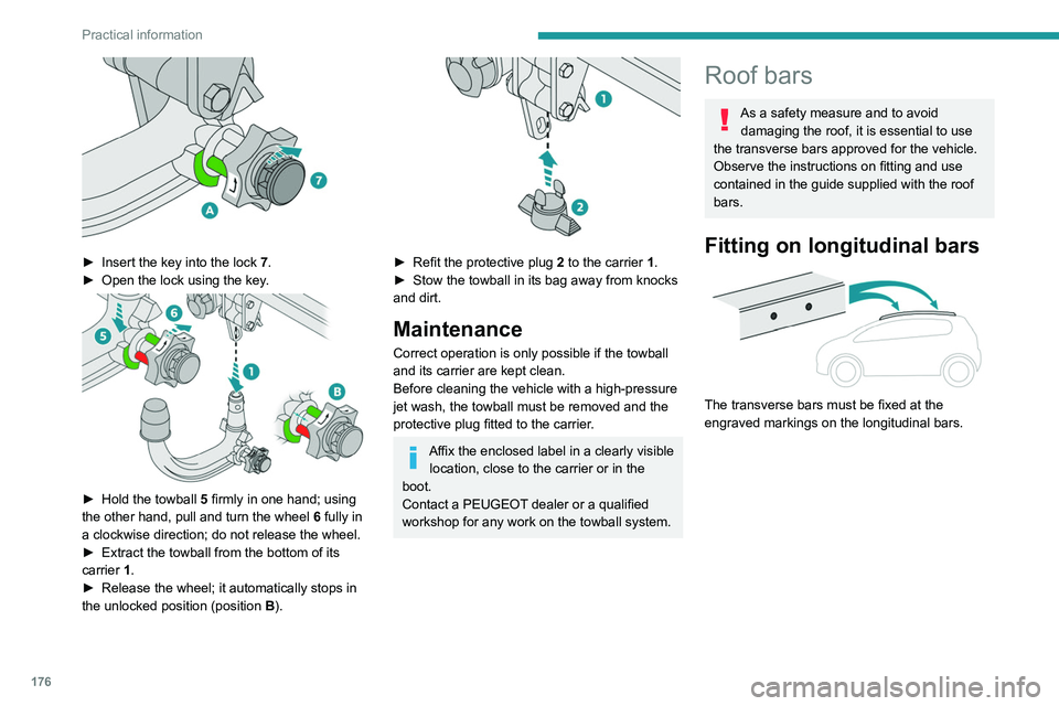
The transverse bars must be fixed at the
engraved markings on the longitudinal bars.
Page 179 of 308
177
Practical information
7Fitting directly to the roof
You must only attach the transverse bars to
the four fixing points located on the roof frame.
These points are concealed by the vehicle doors
when the doors are closed.
The roof bar fixings have a stud which must be
inserted into the opening of each fixing point.
Maximum load distributed over the
transverse roof bars, for a loading height
not exceeding 40 cm (except bicycle carrier):
80 kg.
As this value may change, please verify the
maximum load quoted in the guide supplied
with the roof bars.
If the height exceeds 40 cm, adapt the speed
of the vehicle to the profile of the road to
avoid damaging the roof bars and the fixings
on the vehicle.
Be sure to refer to national legislation in order
to comply with the regulations for transporting
objects that are longer than the vehicle.
Recommendations
Distribute the load uniformly, taking care
to avoid overloading one of the sides.
Arrange the heaviest part of the load as close
as possible to the roof.
Secure the load securely.
Drive gently: the vehicle will be more
susceptible to the effects of side winds and its
stability may be affected.
Regularly check the security and tight
fastening of the roof bars, at least before each
trip.
Remove the roof bars once they are no longer
needed.
Sunroof
Check that the load does not pass below
the roof bars so that it does not impede the
movements of the sunroof - risk of major
damage!
Snow chains
In wintry conditions, snow chains improve
traction as well as the behaviour of the vehicle
when braking.
The snow chains must be fitted only to the front wheels. They must never be
fitted to "space-saver" type spare wheels.
Take account of the legislation specific to each country on the use of snow chains
and the maximum authorised speed.
Use only chains designed to be fitted to the type
of wheel fitted to the vehicle:
Original tyre size Maximum link size 215/65 R17 9 mm
225/55 R18 9 mm
205/55 R19 9 mm
235/50 R19 Not suitable for
chains
For more information on snow chains, contact a
PEUGEOT dealer or a qualified workshop.
Installation tips
► To fit the chains during a journey, stop the
vehicle on a flat surface on the side of the road.
►
Apply the parking brake and position any
wheel chocks under the wheels to prevent
movement of the vehicle.
►
Fit the chains following the instructions
provided by the manufacturer
.
►
Move off gently and drive for a few moments,
without exceeding 31
mph (50 km/h).
Page 186 of 308
184
Practical information
AdBlue® (BlueHDi)
To respect the environment and ensure
compliance with the Euro 6 standard, without
adversely affecting the performance or fuel
consumption of its Diesel engines, PEUGEOT
has taken the decision to equip its vehicles
with a system that associates SCR (Selective
Catalytic Reduction) with a Diesel Particle Filter
(DPF) for the treatment of exhaust gases.
SCR system
Using a liquid called AdBlue® that contains urea,
a catalytic converter turns up to 85% of nitrogen
oxides (NOx) into nitrogen and water, which are
harmless to health and the environment.
The AdBlue® is contained in a special
tank holding about 17 litres.
Its capacity allows a driving range of
approximately 5,600 miles (9,000 km), highly
dependent on your driving style.
An alert system is triggered automatically once
the reserve level is reached: you can then drive
Manual gearbox
The gearbox does not require any maintenance (no oil change).
Automatic gearbox
The gearbox does not require any maintenance (no oil change).
Electric parking brake
This system does not require any routine servicing. However, in the event of a
problem, do not hesitate to have the system
checked by a PEUGEOT dealer or a qualified
workshop.
For more information on the Electric
parking brake, refer to the
corresponding section.
Brake pads
Brake wear depends on the style of
driving, particularly in the case of vehicles
used in town, over short distances. It may be
necessary to have the condition of the brakes
checked, even between vehicle services.
Unless there is a leak in the circuit, a drop in the
brake fluid level indicates that the brake pads
are worn.
After washing the vehicle, moisture, or in wintry conditions, ice can form on the
brake discs and pads: braking efficiency may
be reduced. Gently dab the brakes to dry and
defrost them.
Brake disc wear
For information on checking brake disc
wear, contact a PEUGEOT dealer or a
qualified workshop.
Wheels and tyres
The inflation pressure of all tyres, including the spare wheel, must be
checked on "cold” tyres.
The pressures indicated on the tyre pressure
label are valid for "cold" tyres. If you have driven
for more than 10 minutes or more than 6 miles
(10 kilometres) at over 31 mph (50
km/h), add
0.3 bar (30 kPa) to the values indicated on the
label.
Under-inflation increases fuel
consumption. Non-compliant tyre
pressure causes premature wear on tyres and
has an adverse effect on the vehicle's road
holding - risk of an accident!
Driving with worn or damaged tyres reduces the
braking and road holding performance of the
vehicle. It is recommended to regularly check the
condition of the tyres (tread and sidewalls) and
wheel rims as well as the presence of the valves.
When the wear indicators no longer appear set
back from the tread, the depth of the grooves is less than 1.6 mm; it is imperative to replace the
tyres.
Using different size wheels and tyres from those
specified can affect the lifetime of tyres, wheel
rotation, ground clearance, the speedometer
reading and have an adverse effect on road
holding.
Fitting different tyres on the front and rear axles
can cause the ESC to mistime.
Shock absorbers
It is not easy for drivers to detect when
shock absorbers are worn. Nevertheless,
the shock absorbers have a major impact on
road-holding and braking performance.
For your safety and driving comfort, it is
important to have them regularly checked by a
PEUGEOT dealer or a qualified workshop.
Timing and accessory kits
Timing and accessory kits are used from
the time the engine is started until it is
switched off. It is normal for them to wear over
time.
A
faulty timing or accessory kit can damage
the engine, rendering it unusable. Observe the
recommended replacement frequency, stated in
distance travelled or time elapsed, whichever is
reached first.
Page 195 of 308
193
In the event of a breakdown
8
Kit 2
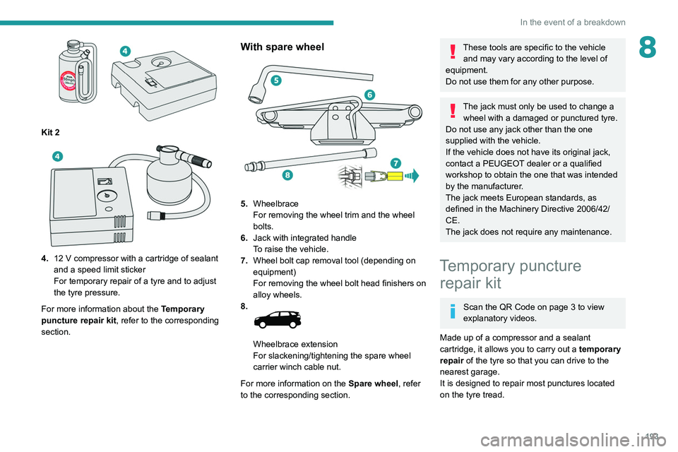
4.12 V compressor with a cartridge of sealant
and a speed limit sticker
For temporary repair of a tyre and to adjust
the tyre pressure.
For more information about the Temporary
puncture repair kit, refer to the corresponding
section.
With spare wheel
5. Wheelbrace
For removing the wheel trim and the wheel
bolts.
6. Jack with integrated handle
To raise the vehicle.
7. Wheel bolt cap removal tool (depending on
equipment)
For removing the wheel bolt head finishers on
alloy wheels.
8.
Wheelbrace extension
For slackening/tightening the spare wheel
carrier winch cable nut.
For more information on the Spare wheel, refer
to the corresponding section.
These tools are specific to the vehicle and may vary according to the level of
equipment.
Do not use them for any other purpose.
The jack must only be used to change a wheel with a damaged or punctured tyre.
Do not use any jack other than the one
supplied with the vehicle.
If the vehicle does not have its original jack,
contact a PEUGEOT dealer or a qualified
workshop to obtain the one that was intended
by the manufacturer.
The jack meets European standards, as
defined in the Machinery Directive 2006/42/
CE.
The jack does not require any maintenance.
Temporary puncture repair kit
Scan the QR Code on page 3 to view
explanatory videos.
Made up of a compressor and a sealant
cartridge,
it allows you to carry out a temporary
repair of the tyre so that you can drive to the
nearest garage.
It is designed to repair most punctures located
on the tyre tread.
Page 197 of 308
195
In the event of a breakdown
8Only the 12 V sockets located at the
front of the vehicle and in the boot can
be used to power the compressor.
The 12
V socket located at the back of the
centre console is not suitable for this purpose.
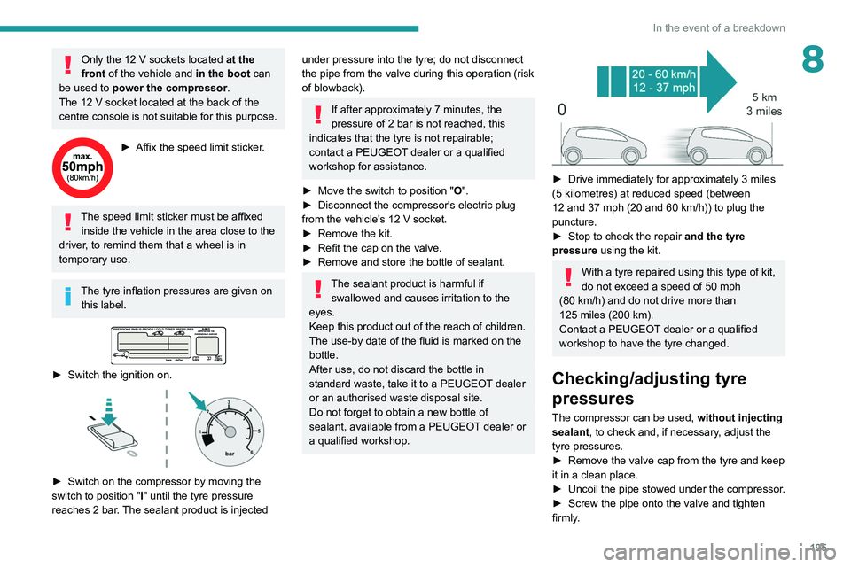
► Affix the speed limit sticker .
The speed limit sticker must be affixed
inside the vehicle in the area close to the
driver, to remind them that a wheel is in
temporary use.
The tyre inflation pressures are given on this label.
► Switch the ignition on.
► Switch on the compressor by moving the
switch to position " I
" until the tyre pressure
reaches 2 bar. The sealant product is injected
under pressure into the tyre; do not disconnect
the pipe from the valve during this operation (risk
of blowback).
If after approximately 7 minutes, the
pressure of 2 bar is not reached, this
indicates that the tyre is not repairable;
contact a PEUGEOT dealer or a qualified
workshop for assistance.
►
Move the switch to position " O
".
►
Disconnect the compressor's electric plug
from the vehicle's 12
V socket.
►
Remove the kit.
►
Refit the cap on the valve.
►
Remove and store the bottle of sealant.
The sealant product is harmful if swallowed and causes irritation to the
eyes.
Keep this product out of the reach of children.
The use-by date of the fluid is marked on the
bottle.
After use, do not discard the bottle in
standard waste, take it to a PEUGEOT dealer
or an authorised waste disposal site.
Do not forget to obtain a new bottle of
sealant, available from a PEUGEOT dealer or
a qualified workshop.
► Drive immediately for approximately 3 miles
(5 kilometres) at reduced speed (between
12 and 37 mph (20 and 60
km/h)) to plug the
puncture.
►
Stop to check the repair
and the tyre
pressure using the kit.
With a tyre repaired using this type of kit,
do not exceed a speed of 50
mph
(80
km/h) and do not drive more than
125
miles (200 km).
Contact a PEUGEOT dealer or a qualified
workshop to have the tyre changed.
Checking/adjusting tyre
pressures
The compressor can be used, without injecting
sealant, to check and, if necessary, adjust the
tyre pressures.
►
Remove the valve cap from the tyre and keep
it in a clean place.
►
Uncoil
the pipe stowed under the compressor.
►
Screw the pipe onto the valve and tighten
firmly
.