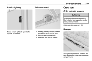
Page 329 of 353

Body conversions327Body conversionsTipper and dropside...................327
Loading information .................327
Tailboard ................................. 328
Sideboards .............................. 329
Lashing eyes ........................... 330
Tipper operation ......................330
Safety prop .............................. 332
Hydraulic oil level ....................333
Toolbox .................................... 334
Exterior lighting ........................334
Cleaning .................................. 334
Vehicle checks ........................ 334
Technical data ......................... 335
Declaration of conformity .........335
Box body .................................... 336
Keys ........................................ 336
Doors ....................................... 336
Roller shutter ........................... 337
Step ......................................... 337
Ladder ..................................... 338
Overcab storage ......................338
Load rails ................................. 338
Interior lighting ......................... 339Crew van.................................... 339
Child restraint systems ............339
Storage .................................... 339Tipper and dropside
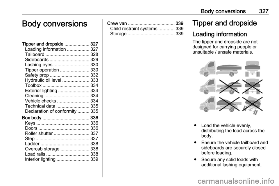
Loading information The tipper and dropside are not
designed for carrying people or
unsuitable / unsafe materials.
● Load the vehicle evenly, distributing the load across the
body.
● Ensure the vehicle tailboard and sideboards are securely closed
before loading.
● Secure any solid loads with additional lashing equipment.
Page 330 of 353

328Body conversions● Place loads from the minimumpracticable height. Do not drop
loads onto the body.
● Do not overload the body.
● Ensure the load will not fall out or
endanger other road users.
● Do not drive with the body tipped.
● Do not drive with the tailboard or sideboards down.
● Do not attempt to tip loads from the body when body sides or
tailboard are closed.
● Observe the safety warning labels placed on the tipper and
dropside bodies.
● Do not attempt to tip loads unless
the vehicle is on solid ground.
● The isolation switch must be in the OFF position when tipping
function is not in use.Caution
Do not exceed the maximum
lateral load of 200 kg (dropside body) and 400 kg (tipper body) as
stated on the head board.
When loading heavy or bulk items, the lashing eyes must be flush with
the body floor to avoid causing any damage.
Refer to the safety warning labels
located on the tipper or dropside
body.
The maximum loading on the
dropside body floor is 230 kg per
80 mm x 80 mm or 80 kg per 50
mm x 50 mm.
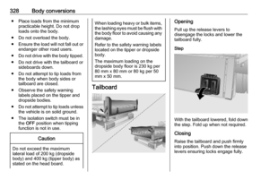
Tailboard
Opening
Pull up the release levers to
disengage the locks and lower the
tailboard fully.
Step
With the tailboard lowered, fold down
the step. Fold up when not required.
Closing
Raise the tailboard and push firmly
into position. Push down the release
levers ensuring locks engage fully.
Page 331 of 353
Body conversions329SwingingThe tailboard lower hinges can be
released to allow the tailboard to
swing from its upper hinges during
tipping operations.9 Warning
To prevent the tailboard becoming
detached from the vehicle, ensure that the upper hinges are engaged
with the release levers in the
locked position.
Release the lower hinges using the
remote lever located at the rear of the body. The tailboard is disengaged
and will swing from its upper hinges.
To lock, engage the lower tailboard
hinges and push the remote lever to
the lock position. Check the tailboard
is secure.
Sideboards9 Warning
The sideboards are heavy.
Take care when lowering the
sideboards, do not allow them to
drop down unassisted.
To open, pull up the release levers to disengage the locks. Lower the
sideboard fully.
To close, raise the sideboard and
push firmly into position. Push down
the release levers ensuring locks
engage fully.
Page 332 of 353

330Body conversionsLashing eyes
Secure heavy objects with lashing
straps attached to the lashing eyes.
Caution
The maximum force applied to the
lashing eyes should not exceed
4000 N or 8000 N at 30°.
Refer to the safety warning labels
located on the tipper or dropside
body.
Additional cargo strap retainers are
located under the tipper body floor.
Tipper operation
9 Warning
Before operating the tipper, apply
the parking brake and select
neutral gear position.
The operator must remain at the
control to ensure tipping and
lowering are performed correctly.
Keep other people away when
tipping function is in use.
Ensure the vehicle is on solid
ground and that the tipper body
can be raised to the maximum
height without touching overhead
obstructions.
The tipper body has two locking pins
which must be always attached while
operating. The locking pins are used
to obtain any one of the three tipping
positions.
Caution
The tipper must not be operated
with locking pins incorrectly
installed.
Pins installed diagonally opposite or in both front pivot positions will
result in damage if tipping is
attempted.
Page 333 of 353
Body conversions331Tipping to the side
Push lever to access the front pivot.
Insert locking pins into the front and
rear pivots on the same side. Ensure the handle and locator on both locking
pins are facing up.
Rotate both locking pins away from
the upright position and secure each
locking chain. Lower the sideboard
fully.
Tipping to the rear9 Warning
To prevent the tailboard becoming
detached from the vehicle, ensure that the upper hinges are engaged
and push the release levers
downwards to engage the locks
fully.
Insert locking pins into the left and
right rear pivots. Ensure the handle
and locator on both locking pins are
facing up. Rotate both locking pins
away from the upright position and
secure each locking chain.
Page 334 of 353

332Body conversionsIsolation switch
The system must be activated using
the isolation switch located on the left- hand side of the chassis. Turn the
isolator switch to the ON position.
When the tipper is not in use, turn the
isolation switch to the OFF position.
Raising and lowering the tipper
The tipper is operated using the
remote control located by the front
seats.
The remote control enables the user
to supervise the operation of the
tipper from outside the vehicle.
Press switch:
â:raiseã:lower
When the tipper is active an acoustic
signal sounds.
The tipper can be stopped at any time
by releasing the switch.
The tipper body will cease moving
automatically when it reaches the
maximum height.
To stop in an emergency, press the
red button.
Store the remote control in the holder when not in use.
Safety cable The safety cable attached to the
tipper body prevents the tipper body
being raised too far. Should the safety
cable become damaged it must be
replaced immediately. Seek the
assistance of a workshop.
Safety prop
The safety prop is located under the
left-hand side of the tipper body and
is provided only to assist in supporting the empty tipper body when tipped to
the rear, for carrying out visual
inspection of the vehicle components.
Page 335 of 353

Body conversions333
Using the safety prop1. Prepare the tipper body for tipping
to the rear.
2. Raise the tipper fully.
3. Raise the safety prop to align with
support on the tipper.
4. Lower the tipper body until the safety prop is in contact with the
tipper.
Stowing the safety prop:
1. Raise the tipper body sufficiently to release the safety prop from its
support.
2. Lower the safety prop into the stowed position.
3. Lower the tipper body.
Hydraulic oil levelCaution
Before any inspection work can be carried out the safety prop must be
in position.
With the tipper fully raised, the
hydraulic oil level must be between
the MIN and MAX marks.Caution
Only use products that have been
tested and approved. Damage
resulting from the use of
nonapproved materials will not be
covered by the warranty.
The use of additives could cause
damage and invalidate the
warranty.
Check the hydraulic oil level after long
driving on bumpy or steep roads.
Have the cause of the loss of
hydraulic oil remedied by a workshop.
Use only hydraulic oil type SAE 10
(ISO 32), or a type Q8 ELI 1298L
suitable for Class 1 conditions.
Page 336 of 353

334Body conversionsToolbox
Unlock using the key provided and
turn latches to open.
Close the door and turn both latches,
then lock with the key.
Caution
Ensure the toolbox door is
properly secure before setting off.
Exterior lighting
Additional exterior lights illuminate in
combination with the side lights.
Have bulbs replaced by a workshop.
Cleaning Dirt or mud which remains dry on thebody may become abrasive and can
damage paint, seals, locks and
hinges.
Clean the following parts if they
become contaminated with dirt:
● Sideboard and tailboard locking latches and hinges.
● Tipper body pivot pins and locating holes.Caution
Do not spray high-pressure water
directly at the hydraulic seals,
pump, reservoir, hydraulic ram ball
joints, or guide clamps.
After cleaning, check, and if
necessary lubricate the components
listed in the owner's checks.
9 Warning
Do not venture under the tipper
body when raised.
Vehicle checks
Check regularly the following items: ● Visually check the subframe mountings, the safety cables andthe hydraulic system. If any of the