2020 NISSAN MURANO radio antenna
[x] Cancel search: radio antennaPage 178 of 518

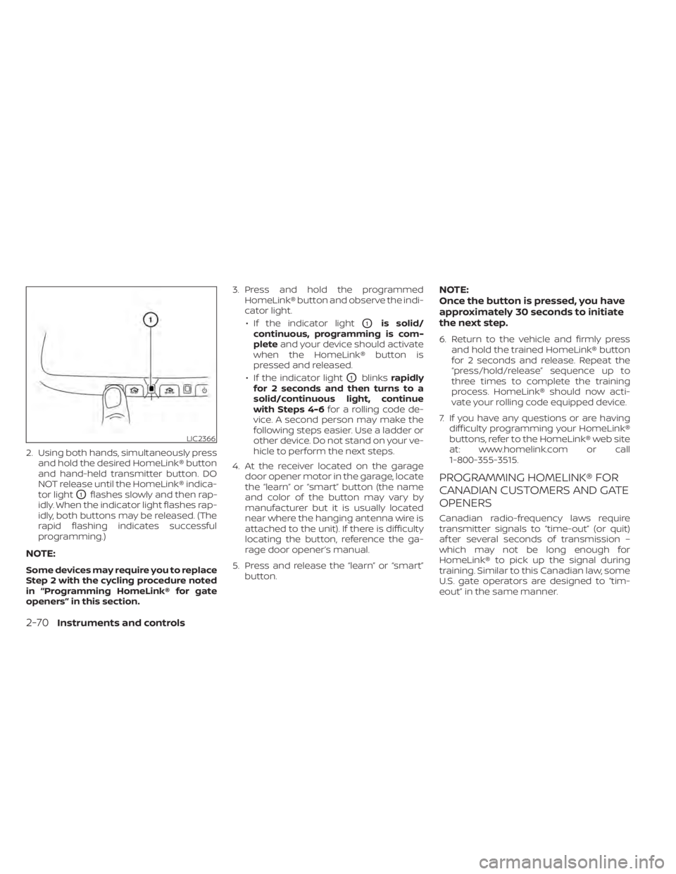
2. Using both hands, simultaneously pressand hold the desired HomeLink® button
and hand-held transmitter button. DO
NOT release until the HomeLink® indica-
tor light
O1flashes slowly and then rap-
idly. When the indicator light flashes rap-
idly, both buttons may be released. (The
rapid flashing indicates successful
programming.)
NOTE:
Some devices may require you to replace
Step 2 with the cycling procedure noted
in “Programming HomeLink® for gate
openers” in this section. 3. Press and hold the programmed
HomeLink® button and observe the indi-
cator light.
• If the indicator light
O1is solid/
continuous, programming is com-
plete and your device should activate
when the HomeLink® button is
pressed and released.
• If the indicator light
O1blinks rapidly
for 2 seconds and then turns to a
solid/continuous light, continue
with Steps 4-6 for a rolling code de-
vice. A second person may make the
following steps easier. Use a ladder or
other device. Do not stand on your ve-
hicle to perform the next steps.
4. At the receiver located on the garage door opener motor in the garage, locate
the “learn” or “smart” button (the name
and color of the button may vary by
manufacturer but it is usually located
near where the hanging antenna wire is
attached to the unit). If there is difficulty
locating the button, reference the ga-
rage door opener’s manual.
5. Press and release the “learn” or “smart” button.
NOTE:
Once the button is pressed, you have
approximately 30 seconds to initiate
the next step.
6. Return to the vehicle and firmly press and hold the trained HomeLink® button
for 2 seconds and release. Repeat the
“press/hold/release” sequence up to
three times to complete the training
process. HomeLink® should now acti-
vate your rolling code equipped device.
7. If you have any questions or are having difficulty programming your HomeLink®
buttons, refer to the HomeLink® web site
at: www.homelink.com or call
1-800-355-3515.
PROGRAMMING HOMELINK® FOR
CANADIAN CUSTOMERS AND GATE
OPENERS
Canadian radio-frequency laws require
transmitter signals to “time-out” (or quit)
af ter several seconds of transmission –
which may not be long enough for
HomeLink® to pick up the signal during
training. Similar to this Canadian law, some
U.S. gate operators are designed to “tim-
eout” in the same manner.
LIC2366
2-70Instruments and controls
Page 223 of 518

4 Monitor, climate, audio, phone and
voice recognition systems
NissanConnect® Owner’s Manual...............4-2
RearView Monitor (if so equipped) ...............4-3
RearView Monitor system operation ..........4-4
How to read the displayed lines ..............4-4
Difference between predicted and
actual distances .............................4-5
How to park with predicted course
lines ..........................................4-6
Adjusting the screen .........................4-8
How to turn on and off predicted
course lines ..................................4-8
RearView Monitor system limitations .........4-8
System maintenance ........................4-9
Intelligent Around View Monitor
(if so equipped) ................................. 4-10
Intelligent Around View Monitor system
operation .................................... 4-11
Difference between predicted and
actual distances ............................ 4-15
How to park with predicted course
lines ......................................... 4-16
How to switch the display ...................4-17Adjusting the screen
........................ 4-18
Intelligent Around View Monitor system
limitations .................................. 4-19
System maintenance ....................... 4-21
Moving Object Detection (MOD)
(if so equipped) ................................. 4-22
MOD system operation ......................4-23
Turning MOD on and off .....................4-24
MOD system limitations .....................4-25
System maintenance .......................4-26
Vents .......................................... 4-26
Heater and Air Conditioner (automatic) .........4-28
Automatic operation ........................ 4-29
Manual operation ........................... 4-30
Operating tips ............................... 4-31
Servicing air conditioner ........................4-31
USB/iPod® charging port .......................4-32
Antenna ........................................ 4-32
Car phone or CB radio .......................... 4-32
iPod®/iPhone® ................................. 4-33
Page 254 of 518

There are USB/iPod® charging ports lo-
cated in the 2nd row on the back of the
center console. These ports will charge
compatible devices.
NOTE:
Only the USB connection port(s) located
below the instrument panel will allow
operation of USB/iPod® devices through
the audio system.The vehicle is equipped with a shark fin
antenna and an antenna pattern is printed
inside the rear window.
CAUTION
• Do not place metalized film near the
rear window glass or attach any
metal parts to it. This may cause poor
reception or noise.
• When cleaning the inside of the rear
window, be careful not to scratch or
damage the rear window antenna.
Lightly wipe along the antenna with a
dampened sof t cloth. When installing a CB, ham radio or car
phone in your vehicle, be sure to observe
the following precautions; otherwise, the
new equipment may adversely affect the
engine control system and other electronic
parts.
WARNING
• A cellular phone should not be used
for any purpose while driving so full
attention may be given to vehicle op-
eration. Some jurisdictions prohibit
the use of cellular phones while
driving.
• If you must make a call while your
vehicle is in motion, the hands free
cellular phone operational mode is
highly recommended. Exercise ex-
treme caution at all times so full at-
tention may be given to vehicle
operation.
• If you are unable to devote full atten-
tion to vehicle operation while talk-
ing on the phone, pull off the road to
a safe location and stop your vehicle.
LHA5039
2nd row
USB/iPod® CHARGING PORT ANTENNACAR PHONE OR CB RADIO
4-32Monitor, climate, audio, phone and voice recognition systems
Page 255 of 518

CAUTION
• Keep the antenna as far away as pos-
sible from the electronic control
modules.
• Keep the antenna wire more than 8 in
(20 cm) away from the electronic
control system harnesses. Do not
route the antenna wire next to any
harness.
• Adjust the antenna standing-wave
ratio as recommended by the
manufacturer.
• Connect the ground wire from the CB
radio chassis to the body.
• For additional information, it is rec-
ommended that you visit a NISSAN
dealer for servicing. “Made for iPod”, “Made for iPhone” and
“Made for iPad” mean that an electronic
accessory has been designed to connect
specifically to iPod, iPhone or iPad, respec-
tively, and has been certified by the devel-
oper to meet Apple performance stan-
dards. Apple is not responsible for the
operation of this device or its compliance
with safety and regulatory standards.
Please note that the use of this accessory
with iPod, iPhone or iPad may affect wire-
less performance.
iPad, iPhone, iPod classic, iPod nano, iPod
shuffle and iPod touch are trademarks of
Apple Inc., registered in the U.S. and other
countries. Lightning is a trademark of
Apple Inc.
iPod®/IPHONE®
Monitor, climate, audio, phone and voice recognition systems4-33
Page 263 of 518

•If the low tire pressure warning light
illuminates while driving, avoid sud-
den steering maneuvers or abrupt
braking, reduce vehicle speed, pull
off the road to a safe location and
stop the vehicle as soon as possible.
Driving with under-inflated tires may
permanently damage the tires and
increase the likelihood of tire failure.
Serious vehicle damage could occur
and may lead to an accident and
could result in serious personal in-
jury. Check the tire pressure for all
four tires. Adjust the tire pressure to
the recommended COLD tire pres-
sure shown on the Tire and Loading
Information label to turn the low tire
pressure warning light off. If you have
a flat tire, replace it with a spare tire
as soon as possible. (For additional
information on changing a flat tire,
refer to “Flat tire” in the “In case of
emergency ” section of this manual.) •
When replacing a wheel without the
TPMS such as the spare tire, when a
spare tire is mounted or a wheel is
replaced, tire pressure will not be in-
dicated, the TPMS will not function
and the low tire pressure warning
light will flash for approximately 1
minute. The light will remain on af ter
1 minute. Have your tires replaced
and/or TPMS system reset as soon as
possible. It is recommended that you
visit a NISSAN dealer for this service.
• Replacing tires with those not origi-
nally specified by NISSAN could af-
fect the proper operation of the
TPMS.
• Do not inject any tire liquid or aerosol
tire sealant into the tires, as this may
cause a malfunction of the tire pres-
sure sensors.CAUTION
• The TPMS may not function properly
when the wheels are equipped with
tire chains or the wheels are buried in
snow.
• Do not place metalized film or any
metal parts (antenna, etc.) on the
windows. This may cause poor re-
ception of the signals from the tire
pressure sensors, and the TPMS will
not function properly.
Some devices and transmitters may tem-
porarily interfere with the operation of the
TPMS and cause the low tire pressure
warning light to illuminate.
Some examples are:
• Facilities or electric devices using similar radio frequencies are near the vehicle.
• If a transmitter set to similar frequencies is being used in or near the vehicle.
• If a computer (or similar equipment) or a DC/AC converter is being used in or near
the vehicle.
The low tire pressure warning light may
illuminate in the following cases:
• If the vehicle is equipped with a wheel and tire without TPMS.
Starting and driving5-7
Page 507 of 518

11 Index
A
Air bag (See supplemental restraint
system).....................1-49Air bag system
Front (See supplemental front impact air
bag system)
................1-56Air bag warning labels............1-69Air bag warning light.........1-70,2-13Air bag warning light,
supplemental..............1-70,2-13Air cleaner...................8-16Air cleaner housing filter..........8-16Air conditionerAir conditioner operation........4-29Air conditioner specification label. .10-13Air conditioner system refrigerant
recommendations............10-8Air conditioner system refrigerant and oil
recommendations............10-8Heater and air conditioner (automatic)
(if so equipped)..............4-28Heater and air conditioner controls.4-29Servicing air conditioner.........4-31Alarm system (See vehicle security
system).................... .2-33All-Wheel Drive............5-124, 6-13Anchor point locations...........1-32Antenna................... .4-32Anti-lock brake warning light........2-9Anti-lock Braking System (ABS).....5-129
Antifreeze...................5-137Armrests.................... .1-6Autolight switch...............2-39Automatic
Automatic drive
positioner
..........3-38, 3-39, 3-40Automatic power window switch. . .2-63Automatic anti-glare inside mirror. . . .3-35Automatic door locks.............3-7Automatic drive
positioner............3-38, 3-39, 3-40Automatic Emergency Braking
(AEB).................. .2-9, 5-89Automatic Emergency Braking (AEB) with
Pedestrian Detection............5-96AWD...................5- 124, 6-13
B
Battery.................5-137, 8-13Charge warning light...........2-10Battery replacement............8-22Key fob...................8-22NISSAN Intelligent Key®.........8-22Before starting the engine.........5-16Belt (See drive belt)..............8-15Blind Spot Warning (BSW).........5-38Booster seats.................1-44Brake
Anti-lock Braking System (ABS). . . .5-129
Brake fluid..................8-11Brake light (See stop light).......8-25Brake system...............5-129Brake warning light............2-10Brake wear indicators.......2-16,8-18Self-adjusting brakes...........8-18Brake Assist..................5-131Brake fluid...................8-11Brake system................5-129Brakes.....................8-18Break-in schedule..............5-123Brightness controlInstrument panel.............2-43Bulb check/instrument panel........2-9Bulb replacement..............8-25
C
C.M.V.S.S. certification label........10-12Capacities and recommended
fuel/lubricants................10-2Car phone or CB radio...........4-32Cargo (See vehicle loading
information)................ .10-14Cargo area storage bin...........2-60Check tire pressure.............2-28Child restraint with top tether strap. . .1-32Child restraints.......1-25,1-26,1-27,1-29LATCH (Lower Anchors and Tethers for
CHildren) System.............1-29