2020 NISSAN ALTIMA maintenance reset
[x] Cancel search: maintenance resetPage 116 of 559

RESETTING THE DRIVE COMPUTER
The drive computer is divided across three
screens:∙ Average Speed
∙ Average Fuel Economy
∙ Trip Distance & Time
1. Press the
but-
tons until you reach the desired drive
computer mode.
2. Press and hold the OK button for ap- proximately 1 second to reset the infor-
mation on the currently displayed
screen.
NOTE:
If you wish to reset all drive computer
values at once, press and hold the OK
button for approximately 3 seconds until
a reset menu appears; and follow the in-
structions.
OIL CONTROL SYSTEM (if so
equipped)
The oil control system can be accessed in
the Maintenance portion of the vehicle in-
formation display settings.
Engine oil information informs the distance
to oil change. Never exceed one year or
7,500 miles (12000 km) between oil change
intervals for the KR20DDET engine or
10,000 miles (16000 km) between oil change
intervals for the PR25DD engine.
Display when
ignition is ON Display timing Action Re-
quired
Engine Oil Ser-
vice due in xxx
miles Remaining oil
life is less than
940 miles
(1500 km). Plan to have
your vehicle
serviced.
Engine Oil Ser-
vice due Remaining oil
life is 0 miles
(0 km). Have your ve-
hicle serviced
within two
weeks or less
than 500 miles
(800 km).
The oil change interval cannot be adjusted
manually.
The distance to oil change interval is calcu-
lated depending on the driving conditions
and set automatically by the oil control sys-
tem. A reminder will be displayed when ap-
proaching the end of the service interval.
When the Factory Reset option is selected
in the vehicle information display, the oil
control system will also be reset to initial
value. Please change the engine oil when
Factory Reset is selected.
CAUTION
If the oil replacement indicator is dis-
played, change the engine oil within
two weeks or less than 500 miles
(800 km).
Operating the vehicle with deteriorated
oil can damage the engine.
Instruments and controls2-21
Page 117 of 559

To reset oil control system:1. Push ignition button to “ON” position.
2. Push the
andbuttons lo-
cated on the steering wheel until “Set-
tings” displays in the vehicle informa-
tion display. Use the
buttons to select “Maintenance”. Then,
press the OK button.
3. Select the “Oil Control System” and press the OK button.
4. Press the OK button according to the reset instructions displayed at the bot-
tom of the “Oil Control System” mainte-
nance screen. For additional information, refer to “Oil con-
trol system” in the “Maintenance and
schedules” section of this manual.
SETTINGS
The setting mode allows you to change the
information displayed in the vehicle infor-
mation display. It also allows you to change
vehicle functions:
∙ VDC Setting
∙ Driver Assistance
∙ TPMS Setting
∙ Clock ∙ Vehicle Settings
∙ Maintenance
∙ Customize Display
∙ Unit/Language
∙ Key-Linked Settings (if so equipped)
∙ Factory Reset
VDC Setting
The VDC Setting menu allows the user to
enable or disable the Vehicle Dynamic
Control (VDC) system.
Menu item
Result
System Allows the user turn the VDC system on or off. For additional information, refer to “Vehicle Dynamic Control
(VDC) system” in the Starting and driving” section of this manual.
2-22Instruments and controls
Page 122 of 559

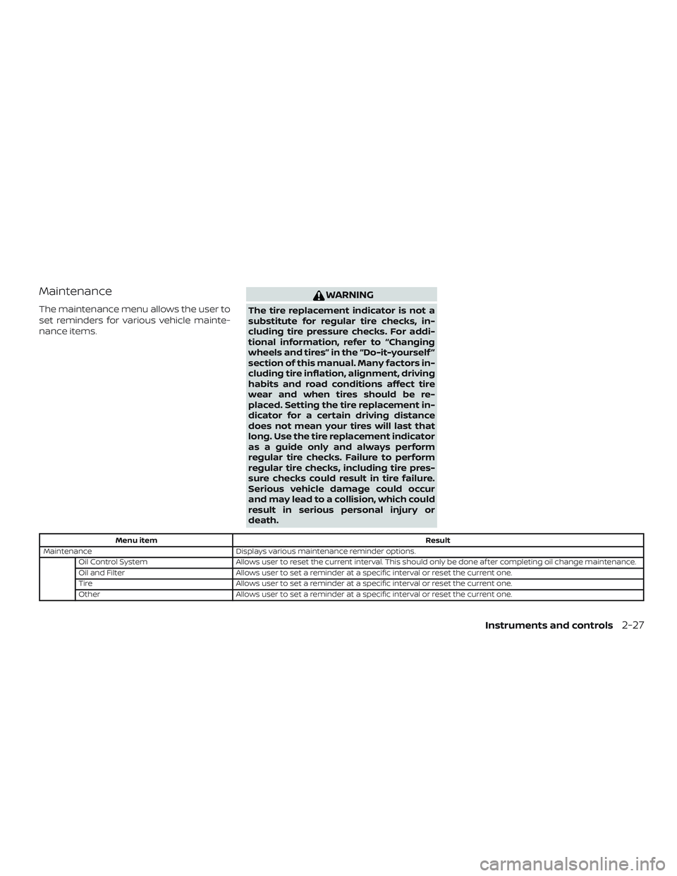
Maintenance
The maintenance menu allows the user to
set reminders for various vehicle mainte-
nance items.
WARNING
The tire replacement indicator is not a
substitute for regular tire checks, in-
cluding tire pressure checks. For addi-
tional information, refer to “Changing
wheels and tires” in the “Do-it-yourself ”
section of this manual. Many factors in-
cluding tire inflation, alignment, driving
habits and road conditions affect tire
wear and when tires should be re-
placed. Setting the tire replacement in-
dicator for a certain driving distance
does not mean your tires will last that
long. Use the tire replacement indicator
as a guide only and always perform
regular tire checks. Failure to perform
regular tire checks, including tire pres-
sure checks could result in tire failure.
Serious vehicle damage could occur
and may lead to a collision, which could
result in serious personal injury or
death.
Menu itemResult
Maintenance Displays various maintenance reminder options.
Oil Control System Allows user to reset the current interval. This should only be done af ter completing oil change maintenance.
Oil and Filter Allows user to set a reminder at a specific interval or reset the current one.
Tire Allows user to set a reminder at a specific interval or reset the current one.
Other Allows user to set a reminder at a specific interval or reset the current one.
Instruments and controls2-27
Page 542 of 559

WARNING
A vehicle equipped with All -Wheel Drive
(AWD) should never be tested using a
two wheel dynamometer (such as the
dynamometers used by some states for
emissions testing), or similar equip-
ment. Make sure you inform the test fa-
cility personnel that your vehicle is
equipped with AWD before it is placed
on a dynamometer. Using the wrong
test equipment may result in drivetrain
damage or unexpected vehicle move-
ment which could result in serious ve-
hicle damage or personal injury.
Due to legal requirements in some states
and Canadian Provinces, your vehicle may
be required to be in what is called the
“ready condition” for an
Inspection/Maintenance (I/M) test of the
emission control system.
The vehicle is set to the “ready condition”
when it is driven through certain driving
patterns. Usually, the ready condition can
be obtained by ordinary usage of the ve-
hicle.
If a powertrain system component is re-
paired or the battery is disconnected, the
vehicle may be reset to a “not ready” condi-
tion. Before taking the I/M test, check the vehicle’s inspection/maintenance test
readiness condition. Place the ignition
switch in the ON position without starting
the engine. If the Malfunction Indicator
Light (MIL) comes on steady for 20 seconds
and then blinks for 10 seconds , the I/M test
condition is “not ready”. If the MIL does not
blink af ter 20 seconds, the I/M test condi-
tion is “ready”. It is recommended that you
visit a NISSAN dealer to set the “ready con-
dition” or to prepare the vehicle for testing.
This vehicle is equipped with an EDR. The
main purpose of an EDR is to record, in
certain collision or near collision-like situa-
tions, such as an air bag deployment or
hitting a road obstacle, data that will assist
in understanding how a vehicle’s systems
performed. The EDR is designed to record
data related to vehicle dynamics and
safety systems for a short period of time,
typically 30 seconds or less. The EDR in this
vehicle is designed to record such data as:
∙ How various systems in your vehicle were operating;
∙ Whether or not the driver and passen- ger safety belts were buckled/fastened;
∙ How far (if at all) the driver was depress- ing the accelerator and/or brake pedal;
and,
∙ How fast the vehicle was traveling.
∙ Sounds are not recorded.
These data can help provide a better un-
derstanding of the circumstances in which
collisions and injuries occur. NOTE: EDR
data are recorded by your vehicle only if a
nontrivial collision situation occurs; no data
are recorded by the EDR under normal driv-
ing conditions and no personal data (e.g.
name, gender, age and collision location)
READINESS FOR INSPECTION/
MAINTENANCE (I/M) TEST EVENT DATA RECORDERS (EDR)
Technical and consumer information10-21